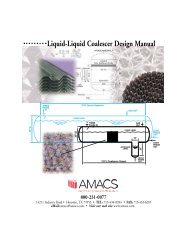
Mesh and Vane Mist Eliminator Brochure - AMACS Process Tower ...
Mesh and Vane Mist Eliminator Brochure - AMACS Process Tower ...
Mesh and Vane Mist Eliminator Brochure - AMACS Process Tower ...

You also want an ePaper? Increase the reach of your titles
YUMPU automatically turns print PDFs into web optimized ePapers that Google loves.
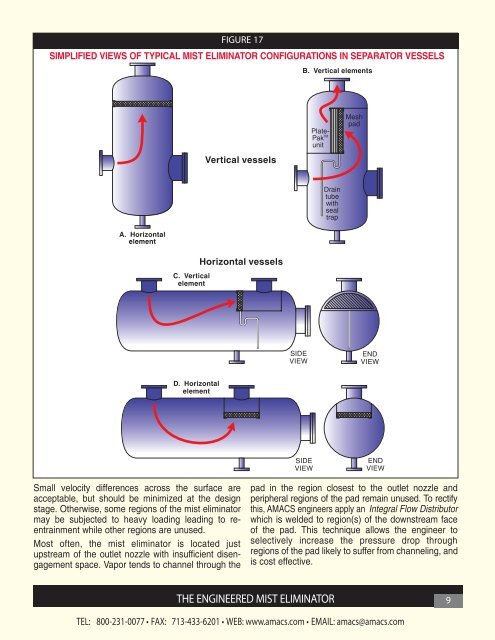
FIGURE 17<br />
SIMPLIFIED VIEWS OF TYPICAL MIST ELIMINATOR CONFIGURATIONS IN SEPARATOR VESSELS<br />
Small velocity differences across the surface are<br />
acceptable, but should be minimized at the design<br />
stage. Otherwise, some regions of the mist eliminator<br />
may be subjected to heavy loading leading to reentrainment<br />
while other regions are unused.<br />
Most often, the mist eliminator is located just<br />
upstream of the outlet nozzle with insufficient disengagement<br />
space. Vapor tends to channel through the<br />
pad in the region closest to the outlet nozzle <strong>and</strong><br />
peripheral regions of the pad remain unused. To rectify<br />
this, <strong>AMACS</strong> engineers apply an Integral Flow Distributor<br />
which is welded to region(s) of the downstream face<br />
of the pad. This technique allows the engineer to<br />
selectively increase the pressure drop through<br />
regions of the pad likely to suffer from channeling, <strong>and</strong><br />
is cost effective.<br />
THE ENGINEERED MIST ELIMINATOR 9<br />
TEL:<br />
800-231-0077 • FAX: 713-433-6201 • WEB: www.amacs.com • EMAIL: amacs@amacs.com