Ask AMACS Solution with MistFix - AMACS Process Tower Internals
Ask AMACS Solution with MistFix - AMACS Process Tower Internals
Ask AMACS Solution with MistFix - AMACS Process Tower Internals

You also want an ePaper? Increase the reach of your titles
YUMPU automatically turns print PDFs into web optimized ePapers that Google loves.
<strong>AMACS</strong><br />
<strong>AMACS</strong> strictly prohibits publication, distribution,<br />
or dissemination of this paper or any part of it, or<br />
conversion of this digital version into any other<br />
format, <strong>with</strong>out prior written permission of Amacs<br />
We need a mist eliminator<br />
in that knockout drum!<br />
Can we add one <strong>with</strong>out<br />
overhauling the vessel<br />
I<br />
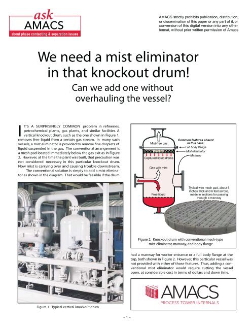
T’S A SURPRISINGLY COMMON problem in refineries,<br />
petrochemical plants, gas plants, and similar facilities. A<br />
vertical knockout drum, such as the one shown in Figure 1,<br />
removes free liquid from a certain gas stream. In many such<br />
vessels, a mist eliminator is provided to remove fine droplets of<br />
liquid suspended in the gas. The conventional arrangement is<br />
a mesh pad located immediately below the gas exit as in Figure<br />
2. However, at the time the plant was built, that precaution was<br />
not considered necessary in this particular knockout drum.<br />
Now mist is carrying over and causing trouble downstream.<br />
The conventional solution is simply to add a mist eliminator<br />
as shown in the diagram. That would be feasible if the drum<br />
Figure 2. Knockout drum <strong>with</strong> conventional mesh-type<br />
mist eliminator, manway, and body<br />
had a manway for worker entrance or a full body flange at the<br />
top, both shown in Figure 2. However, this particular vessel was<br />
not provided <strong>with</strong> either of those features. Thus, adding a conventional<br />
mist eliminator would require cutting the vessel<br />
open, at considerable cost in terms of dollars and down time.<br />
Figure 1. Typical vertical knockout drum<br />
– 1 –
A potential solution: the <strong>MistFix</strong> ®<br />
mist eliminator<br />
However, there is another solution that works in many<br />
cases such as this. It is a patented type of mist eliminator manufactured<br />
by <strong>AMACS</strong> <strong>Process</strong> <strong>Tower</strong> <strong>Internals</strong> called <strong>MistFix</strong><br />
(U. S. patent number 5,985,004). As seen in Figure 3, a <strong>MistFix</strong><br />
unit is a hollow cylinder of the same sort of knitted mesh that<br />
conventional mesh pads are made of. It is designed to be<br />
inserted in a vertical flanged gas exit nozzle, being secured by a<br />
base ring that fits between the flanges. Rigidity is provided by a<br />
cylindrical frame around which the mesh is wrapped (not<br />
shown in the diagram), and the bottom end is closed by a plate.<br />
<strong>MistFix</strong> units are widely applicable for exit nozzles <strong>with</strong> inside<br />
diameter no less than about 6 inches, provided that the length<br />
necessary to achieve an efficient gas velocity range is no greater<br />
than about 54 inches. By use of special high-efficiency highdensity<br />
mesh styles, the radial thickness of the mesh can be as<br />
low as two inches - sometimes even less.<br />
Figure 3. <strong>MistFix</strong><br />
®<br />
insertion mist eliminator<br />
Figure 4. Gas ows through the mesh of a <strong>MistFix</strong> unit<br />
horizontally, as it does through a vertical mesh<br />
pad in some knockout drums such as this one.<br />
A <strong>MistFix</strong> mist eliminator functions in the same manner as<br />
a mesh pad mounted vertically, such as in the knockout drum<br />
shown in Figure 4. Gas flows horizontally through the mesh,<br />
and captured liquid drains downward. In a <strong>MistFix</strong> unit as in<br />
Figure 3, mist-free gas emerges from the mesh into the central<br />
cavity and ows upward into the gas exit pipe.<br />
The <strong>MistFix</strong> unit is sized to closely inside the exit nozzle.<br />
Its length depends on the case at hand. The longer the mesh<br />
cylinder, the greater the cross-sectional area of the mesh for gas<br />
ow, and the lower the gas velocity for a given volumetric<br />
throughput. The length of the mesh cylinder is selected so that<br />
the velocity through the mesh is <strong>with</strong>in an optimum range for<br />
the application.<br />
<strong>MistFix</strong> units can be advantageous for retrofitting even<br />
large vessels that have manways. This method avoids the usual<br />
down time and expense for installing a conventional mist eliminator.<br />
There is no need to purge and ventilate the vessel, build<br />
a inside, weld supports for the mist eliminator, and<br />
recertify the vessel to ASME code.<br />
Vessels <strong>with</strong> special linings for corrosion resistance but no<br />
mist eliminators are especially appropriate candidates for<br />
retrofit <strong>with</strong> <strong>MistFix</strong> units. If increased throughput causes mist<br />
and the need for a mist eliminator, it is difficult to attach a support<br />
ring <strong>with</strong>out penetrating the lining. Even slight damage to<br />
the lining can lead to corrosion and possible failure of the vessel.<br />
A <strong>MistFix</strong> unit may be the only viable alternative.<br />
Even for new construction, <strong>MistFix</strong> mist eliminators are<br />
preferred over conventional alternatives in some cases. One<br />
instance is applications requiring frequent replacement<br />
because of fouling or corrosion. Another is those in which<br />
entering the vessel for inspection and replacement would be<br />
burdensome because down time cannot be tolerated, or the<br />
process material is exceptionally hazardous, etc.<br />
Despite the advances that have been made in the technology,<br />
there is still as much art as science in the design and specof<br />
mesh and vane mist eliminators. For all but the<br />
ification<br />
most experienced users, proper application depends on consultation<br />
<strong>with</strong> the manufacturer’s engineers. This is especially so<br />
the case of <strong>MistFix</strong> mist eliminators.<br />
This paper provides some background for those discussions<br />
<strong>with</strong> <strong>AMACS</strong> engineers. Included are some general<br />
guidelines for applying <strong>MistFix</strong> mist eliminators , particularly in<br />
retrofits The information is not intended to enable users to<br />
design and specify these devices <strong>with</strong>out assistance.<br />
Applying general mist eliminator<br />
design to a <strong>MistFix</strong> unit<br />
Although <strong>MistFix</strong> mist eliminators are cylindrical, they are<br />
designed and specified for an application by the same methods<br />
as conventional flat mesh and vane units. The overall general<br />
procedure is as follows:<br />
1. Estimate the size distribution of mist droplets.<br />
2. Specify the required separation in terms of the<br />
percent of mist to be removed.<br />
3. Considering droplet size, mist load, liquid characteristics,<br />
and the characteristics of various mesh types in terms of<br />
droplet capture efficiency, corrosion resistance , mist load<br />
capacity, and wettability by the mist liquid, tentatively<br />
– 2 –
choose a mesh style and material and the radial thickness<br />
of the cylindrical mesh pad to achieve the required separation<br />
at optimum gas velocity.<br />
4. Choose a design value for the vapor load factor K that is<br />
appropriate for the foregoing assumptions, and calculate<br />
the optimum design velocity through the mesh using the<br />
Souders-Brown equation (explained next).<br />
5. Based on the optimum velocity, the expected volumetric<br />
throughput, and the assumed diameter of the <strong>MistFix</strong><br />
unit, calculate the necessary cross-sectional area for gas<br />
ow through the mesh and thus the length of the unit<br />
(also explained below).<br />
6. Estimate separation efficiency and pressure drop <strong>with</strong>in<br />
the required turndown range.<br />
7. If the estimated results are not acceptable, repeat steps 3<br />
through 6 <strong>with</strong> a different mesh style, material, or thickness,<br />
or <strong>with</strong> a different diameter of the <strong>MistFix</strong> unit if<br />
that option is available.<br />
8. Check for conformance <strong>with</strong> internal gas ow guidelines<br />
and for height available for the <strong>MistFix</strong> unit inside the<br />
vessel, and revise as necessary.<br />
For explanations of those methods as applied to a broad<br />
range of devices, see Amacs literature such as “<strong>AMACS</strong> Mesh & Vane<br />
Mist Eliminators.”<br />
Regarding Step 3 above, a very wide variety of mesh types<br />
are available for conventional pads and <strong>MistFix</strong> units. Standard<br />
wire diameters are 0.011 inch and 0.006 inch. Standard alloys<br />
are 304 and 316 SS, but others such as Inconel and Hastelloy are<br />
often supplied for certain corrosive services . Plastic monofilaments<br />
include polypropylene and Teflon Yarns co-knit <strong>with</strong><br />
metal or plastic mesh for capturing very fine mist droplets are<br />
commonly provided in Dacron, glass fiber polypropylene, and<br />
Teflon. It may be that the optimum mesh selection is a combination<br />
of different types. For instance, an outer layer of fine,<br />
dense mesh or co-knit yarn may serve to coalesce very small<br />
mist droplets, forming larger entrained droplets that are in turn<br />
captured by an inner layer of coarser bare mesh.<br />
Efficiency and pressure-drop estimations (Step 6 above)<br />
are beyond the scope of this paper , typically requiring consultation<br />
by Amacs engineers. The full spectrum of efficiencies can<br />
be provided by a <strong>MistFix</strong> unit, from a general-purpose efficiency<br />
of 99% of 10-micron and larger droplets to a high efficiency of<br />
99.9% of 2-micron and larger droplets. Typically the pressure<br />
drop across a <strong>MistFix</strong> device is 2 to 4 inches of water column.<br />
Step 4 above is conducted for a <strong>MistFix</strong> unit in the same<br />
way as for a conventional flat mist eliminator. These devices are<br />
sized for cross-sectional area to achieve a design velocity<br />
according to the Souders-Brown vapor load factor K:<br />
The Souders-Brown equation allows experimental data<br />
taken <strong>with</strong> air and water on a certain mist eliminator to be generalized<br />
to the same type of device <strong>with</strong> gases and liquids having<br />
generally similar characteristics but different densities.<br />
Once a design value of the vapor load factor K is established for<br />
a mist eliminator type, the design velocity can be calculated for<br />
various combinations of gases and liquids.<br />
The appropriate design value of K for a <strong>MistFix</strong> unit<br />
depends on a number of factors that are beyond the scope of<br />
this paper. As a first approximation in most cases, however, one<br />
can use the figure that is commonly recommended for vertical<br />
flat mesh pads: 0.42 feet per second. This K factor corresponds<br />
to a velocity of 12 feet per second in the reference case of water<br />
and air at room conditions.<br />
It is assumed that the mist load is less than 0.1% volumetric,<br />
which is equivalent to 0.5 gpm per square foot at 10 feet per<br />
second. Greater mist loads require special considerations.<br />
It is also assumed that the pressure in the vessel is between<br />
atmospheric and about 85 psig. The K value should be de-rated<br />
by 0.1 (24%) for each 100 psi increase above atmospheric pressure.<br />
Sizing a <strong>MistFix</strong> unit<br />
Applying the design velocity to size a <strong>MistFix</strong> unit (Step 5<br />
above) is a bit more tricky than <strong>with</strong> a conventional flat mesh<br />
pad. In a flat pad, the velocity is the sameth roughout the padat<br />
least ideally to a first approximation.<br />
That velocity is simply<br />
the volumetric flow rate divided by the cross-sectional area of<br />
the pad, which is the same throughout the thickness of the pad.<br />
However, in the cylindrical mesh pad of a <strong>MistFix</strong> unit, the<br />
cross-sectional area through which the gas enters the mesh at<br />
the outer surface is larger than the area of the inner surface.<br />
(See Figure 5.) Thus, the velocity increases as the gas fl ows radially<br />
inward.<br />
The design velocity is the value of the superficial or average<br />
gas velocity through the mesh (volumetric ow rate divided by<br />
cross-sectional area) that is optimal for the particular liquid and<br />
gas involved. It is intended to lie about 10% below the upper<br />
end of the operating velocity range. That upper end is the point<br />
at which increasing gas velocity begins to cause excessive reentrainment<br />
of captured liquid from the mesh. The lower end<br />
of the operating range, in turn, is the point at which decreasing<br />
gas velocity begins to cause unacceptably poor droplet capture<br />
y.<br />
Figure 5. A special consideration in selecting a <strong>MistFix</strong> unit:<br />
higher velocity at the inner surface than at the outer<br />
– 3 –
Figure 6. S sizing example<br />
Depending on the judgment of the designer , the design<br />
velocity may be established at the inner or outer surface or anywhere<br />
in between. The most conservative and cautious<br />
approach is to set the inner-surface velocity at the design value,<br />
to make sure re-entrainment is avoided. Velocities farther out<br />
toward the outer surface will be progressively lower.<br />
Figure 6 depicts the application of Steps 4 and 5 above to a<br />
typical simplified design case. A knockout drum <strong>with</strong> design<br />
throughput of 3,600 actual cubic feet per minute has an 18-inch<br />
gas exit nozzle. A <strong>MistFix</strong> unit is to be inserted in the nozzle,<br />
and the proper length is to be determined. The pressure is less<br />
than 85 psig. The owing materials are hydrocarbon vapor and<br />
liquid <strong>with</strong> densities of 0.31 and 45.2 pounds per cubic foot.<br />
Using a design K factor of 0.42 as discussed before, the<br />
design velocity turns out to be 4.91 feet per second. The crosssectional<br />
area required to achieve that velocity is 12.2 square<br />
feet. For this <strong>MistFix</strong> unit, the length to achieve that design<br />
velocity at the outer surface is 31.1 inches. By comparison, if a<br />
conventional round horizontal mesh pad were used, that<br />
design cross-section would correspond to a diameter of 47.3<br />
inches.<br />
the unit, and avoiding strong turbulence and fluid shear around<br />
and below the <strong>MistFix</strong> unit. Consultation by Amacs engineers is<br />
especially important in this area.<br />
To prevent uneven flow through the mesh, the bottom end<br />
of the device should be well clear of the inlet stream - more<br />
than about half a vessel radius above the top of the inlet nozzle.<br />
In many cases, undesirable turbulence can be diminished by a<br />
properly selected inlet feed device. If a manway is not available for<br />
installing such a device, it may be possible to use a diffuser<br />
designed for insertion through the inlet nozzle as shown in<br />
Figure 7. To control flow inequality along the length of the<br />
<strong>MistFix</strong> unit, variation in thickness or density of the mesh may<br />
be incorporated.<br />
Height and ow considerations<br />
in the vessel<br />
Special considerations for <strong>MistFix</strong> units are also involved in<br />
Step 8 above, regarding available vessel height and internal fl ow<br />
guidelines. The length of a <strong>MistFix</strong> device is of course constrained<br />
by the vertical space inside the vessel as well as the typical<br />
54-inch maximum. The length limit is to allow good<br />
drainage of captured liquid, <strong>with</strong>out excessive flooding in the<br />
lower end of the <strong>MistFix</strong> unit. Four and a half feet is a generally<br />
appropriate maximum for typical wire mesh, low-viscosity<br />
liquid, and a typical light mist load of about 0.1% volumetric.<br />
The length limit must be shortened for high viscosity, heavy<br />
mist loads, and high-density mesh.<br />
Flow guidelines in turn, encompass two considerations:<br />
maintaining an even velocity profile throughout the length of<br />
Figure 7. Use of an inlet feed device to help maintain even flow<br />
through a <strong>MistFix</strong> unit when it extends near the<br />
inlet nozzle of the knockout drum<br />
– 4 –
In-line chamber for small<br />
gas exit nozzles<br />
If the existing gas exit nozzle on the knockout drum is too<br />
small for inserting a <strong>MistFix</strong> unit, an in-line chamber can sometimes<br />
be provided for the device directly above the knockout<br />
drum as shown in Figure 8. This expedient comes into play<br />
when the exit nozzle diameter is smaller than the minimum 6<br />
inches, or when the <strong>MistFix</strong> unit must be bigger than the nozzle<br />
to provide enough ow area <strong>with</strong>in the available vessel height.<br />
In the special circumstances where this ation is<br />
feasible, it provides all<br />
that a <strong>MistFix</strong> mist eliminator<br />
brings when inserted in a knockout drum. C<br />
mesh pads and vane units can also be mounted in this fashion.<br />
However, in such cases, the chamber must be considerably larger<br />
than for an equivalent <strong>MistFix</strong> unit. Each application of this<br />
type is unique and requires consultation of Amistco engineers.<br />
Chemical<br />
Figure 8. Mounting a Mist-Fix unit in a chamber<br />
above the knockout drum<br />
Case Histories<br />
plant reduces cleaning cycle<br />
A Midwester production plant had to shut down two<br />
identical vertical gas-liquid separators four times a year to<br />
replace the horizontal mesh pads due to fouling s.<br />
Each shutdown lasted two days because of the time required for<br />
reach the<br />
mesh pad. The plant was operating near maximum capacity, so<br />
any down time dir the company’s bottom line.<br />
The separators were 36 inches in diameter and 84 inches<br />
high. The incoming stream consisted of gas <strong>with</strong> a density<br />
of 0.25 lb/ft 3 and a throughput of 3,600 actual cubic feet per<br />
minute. The feed contained less than 0.1% water <strong>with</strong> droplets<br />
greater than 10 microns in size, and also traces s. The<br />
gas outlet nozzle had an inside diameter of 12 inches.<br />
Based on the process conditions, a 12- inch <strong>MistFix</strong> unit<br />
<strong>with</strong> a length of 30 inches for each separator, using 316 SS mesh.<br />
these devices have been operating very successfully for several<br />
years. The plant keeps spare <strong>MistFix</strong> units in inventory and can<br />
easily change a fouled <strong>MistFix</strong> in a few hours.<br />
y capacity increase and<br />
downtime reduction<br />
A medium-size Midwestern ry needed to increase the<br />
capacity of three knockout drums by 10%. At the same time,<br />
management was looking for ways to reduce the periodic down<br />
time of the vessels for replacing the horizontal mesh pads. The<br />
drums had an outside diameter of 60 inches and a height of 108<br />
inches. For each vessel, the gas flow rate was 8,000 ACFM. The<br />
gas was fuel gas <strong>with</strong> a density of 0.15 lb/ft . 3 The mist consisted<br />
of oil <strong>with</strong> a density of 50 lb/ft 3 , the liquid load being less<br />
than 0.1%. The exit nozzles were 16 inches in diameter.<br />
One of the knockout drums was chosen for retrofit <strong>with</strong> a<br />
<strong>MistFix</strong> unit on a trial basis. The design was for a diameter of 16<br />
inches, a length of 48 inches, Monel for the mesh, and 316 SS for<br />
the frame. The device has been operating successfully for 16<br />
months. Because of this positive experience, the refinery is considering<br />
<strong>MistFix</strong> units for the other two separators as well as addapplications<br />
in the itional<br />
plant.<br />
Specialty chemicals plant <strong>with</strong> lined vessels<br />
A specialty chemicals plant had increased its capacity over<br />
the years and was operating <strong>with</strong>out mist eliminator pads in<br />
any of its vessels. Now frequent liquid carryover in several<br />
places required corrective action. Unfortunately, most of the<br />
vessels involved were lined for corrosion resistance. Adding a<br />
mesh pad would require welding a support ring to the vessel<br />
wall, entailing considerable expense to restore the lining.<br />
A 36 inch long <strong>MistFix</strong> unit was designed for one of the<br />
vapor-liquid separators <strong>with</strong> 42-inch outside diameter and 108-<br />
inch height. The diameter of the gas outlet nozzle was 10 inches.<br />
The gas flow rate was 3,000 ACFM, and the gas density was<br />
0.007 lb/ft 3 . To resist corrosion, the mesh was made of Ni-200<br />
and Teflon Using a <strong>MistFix</strong> unit in the gas outlet avoided damaging<br />
the vessel lining. As a result of success in that retrofit the<br />
plant has ordered additional <strong>MistFix</strong> units for other lined vessels<br />
14211 Industry Street, Houston, TX. 77053<br />
Phone 713-434-0934 Fax 713-433-6201<br />
amacs@amacs.com www.amacs.com<br />
24-hour Emergency Service: 800-231-0077<br />
<strong>MistFix</strong> is a trademark of <strong>AMACS</strong> <strong>Process</strong> <strong>Tower</strong> <strong>Internals</strong>. <strong>AMACS</strong> has endeavored to assure that all information in this publication is accu rate. However, nothing herein is intended as a guarantee or warranty.<br />
– 5 –