Ask AMACS Solution with MistFix - AMACS Process Tower Internals
Ask AMACS Solution with MistFix - AMACS Process Tower Internals
Ask AMACS Solution with MistFix - AMACS Process Tower Internals

Create successful ePaper yourself
Turn your PDF publications into a flip-book with our unique Google optimized e-Paper software.
A potential solution: the <strong>MistFix</strong> ®<br />
mist eliminator<br />
However, there is another solution that works in many<br />
cases such as this. It is a patented type of mist eliminator manufactured<br />
by <strong>AMACS</strong> <strong>Process</strong> <strong>Tower</strong> <strong>Internals</strong> called <strong>MistFix</strong><br />
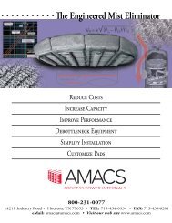
(U. S. patent number 5,985,004). As seen in Figure 3, a <strong>MistFix</strong><br />
unit is a hollow cylinder of the same sort of knitted mesh that<br />
conventional mesh pads are made of. It is designed to be<br />
inserted in a vertical flanged gas exit nozzle, being secured by a<br />
base ring that fits between the flanges. Rigidity is provided by a<br />
cylindrical frame around which the mesh is wrapped (not<br />
shown in the diagram), and the bottom end is closed by a plate.<br />
<strong>MistFix</strong> units are widely applicable for exit nozzles <strong>with</strong> inside<br />
diameter no less than about 6 inches, provided that the length<br />
necessary to achieve an efficient gas velocity range is no greater<br />
than about 54 inches. By use of special high-efficiency highdensity<br />
mesh styles, the radial thickness of the mesh can be as<br />
low as two inches - sometimes even less.<br />
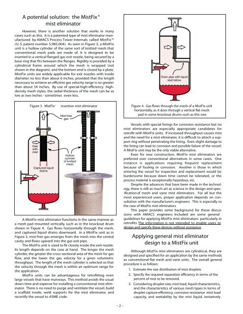
Figure 3. <strong>MistFix</strong><br />
®<br />
insertion mist eliminator<br />
Figure 4. Gas ows through the mesh of a <strong>MistFix</strong> unit<br />
horizontally, as it does through a vertical mesh<br />
pad in some knockout drums such as this one.<br />
A <strong>MistFix</strong> mist eliminator functions in the same manner as<br />
a mesh pad mounted vertically, such as in the knockout drum<br />
shown in Figure 4. Gas flows horizontally through the mesh,<br />
and captured liquid drains downward. In a <strong>MistFix</strong> unit as in<br />
Figure 3, mist-free gas emerges from the mesh into the central<br />
cavity and ows upward into the gas exit pipe.<br />
The <strong>MistFix</strong> unit is sized to closely inside the exit nozzle.<br />
Its length depends on the case at hand. The longer the mesh<br />
cylinder, the greater the cross-sectional area of the mesh for gas<br />
ow, and the lower the gas velocity for a given volumetric<br />
throughput. The length of the mesh cylinder is selected so that<br />
the velocity through the mesh is <strong>with</strong>in an optimum range for<br />
the application.<br />
<strong>MistFix</strong> units can be advantageous for retrofitting even<br />
large vessels that have manways. This method avoids the usual<br />
down time and expense for installing a conventional mist eliminator.<br />
There is no need to purge and ventilate the vessel, build<br />
a inside, weld supports for the mist eliminator, and<br />
recertify the vessel to ASME code.<br />
Vessels <strong>with</strong> special linings for corrosion resistance but no<br />
mist eliminators are especially appropriate candidates for<br />
retrofit <strong>with</strong> <strong>MistFix</strong> units. If increased throughput causes mist<br />
and the need for a mist eliminator, it is difficult to attach a support<br />
ring <strong>with</strong>out penetrating the lining. Even slight damage to<br />
the lining can lead to corrosion and possible failure of the vessel.<br />
A <strong>MistFix</strong> unit may be the only viable alternative.<br />
Even for new construction, <strong>MistFix</strong> mist eliminators are<br />
preferred over conventional alternatives in some cases. One<br />
instance is applications requiring frequent replacement<br />
because of fouling or corrosion. Another is those in which<br />
entering the vessel for inspection and replacement would be<br />
burdensome because down time cannot be tolerated, or the<br />
process material is exceptionally hazardous, etc.<br />
Despite the advances that have been made in the technology,<br />
there is still as much art as science in the design and specof<br />
mesh and vane mist eliminators. For all but the<br />
ification<br />
most experienced users, proper application depends on consultation<br />
<strong>with</strong> the manufacturer’s engineers. This is especially so<br />
the case of <strong>MistFix</strong> mist eliminators.<br />
This paper provides some background for those discussions<br />
<strong>with</strong> <strong>AMACS</strong> engineers. Included are some general<br />
guidelines for applying <strong>MistFix</strong> mist eliminators , particularly in<br />
retrofits The information is not intended to enable users to<br />
design and specify these devices <strong>with</strong>out assistance.<br />
Applying general mist eliminator<br />
design to a <strong>MistFix</strong> unit<br />
Although <strong>MistFix</strong> mist eliminators are cylindrical, they are<br />
designed and specified for an application by the same methods<br />
as conventional flat mesh and vane units. The overall general<br />
procedure is as follows:<br />
1. Estimate the size distribution of mist droplets.<br />
2. Specify the required separation in terms of the<br />
percent of mist to be removed.<br />
3. Considering droplet size, mist load, liquid characteristics,<br />
and the characteristics of various mesh types in terms of<br />
droplet capture efficiency, corrosion resistance , mist load<br />
capacity, and wettability by the mist liquid, tentatively<br />
– 2 –