ACS Coalescer (PDF) - AMACS Process Tower Internals
ACS Coalescer (PDF) - AMACS Process Tower Internals
ACS Coalescer (PDF) - AMACS Process Tower Internals

Create successful ePaper yourself
Turn your PDF publications into a flip-book with our unique Google optimized e-Paper software.
Source Stability Droplet SizeRangeFlash Drum Emulsionswith >5 % Dispersed Phase,Static MixersFlash Drum Emulsions with
DROPLETDROPLETseparation of finer or more stable emulsions (Table 2).Note that fine media will also capture or filter fine solidparticulates from the process stream. Therefore, unlessthe emulsion is very clean, an upstream duplex straineror filter is needed to protect a high efficiency coalescer.MediaSourceSeparators withCoarse Emulsions& Static MixersOverhead Drums,Extraction Columns,Distillation <strong>Tower</strong> Feeds,Impeller MixersSteam Stripper Bottoms,Caustic Wash Drums,High Pressure DropMixing ValvesHaze from Cooling inBulk Liquid Phase,Surfactants GivingEmulsions with VeryLow Interfacial TensionMax DropletDiameter, µCorrugatedSheets 40-1000Wire Mesh,Wire Wool 20-300Co-Knits ofWire &PolymerGlass Mat,Co-Knits ofWire &Fiberglass10-200Flow Rangegpm/ft 215-75(35-180 m 3 /hr/m 2 )7.5-45(20-110 m 3 /hr/m 2 )7.5-45(20-110 m 3 /hr/m 2 )1-25 7.5-45(20-110 m 3 /hr/m 2 )Media Hydro/Oleophilic Porosity Target Size Fouling/CostMetal/PlasticCorrugated SheetsWire/Plastic MeshWire WoolWire/PolymerCo-KnitsWire/FG Co-Knits,Glass MatdArea for efficientFilamentd/2droplet collection Dd/2dFIGURE 6DROPLET INTERCEPTIONH/OH/OHOHDroplet TrajectoryDroplet Trajectory98-99%95-99%94-98%92-96%Table 23/8" - 1"Spacing/Crimps.002" - .011"21-35 micron8 - 10 micronLiquid FlowStreamlinesStep 2 – Droplet CoalescenceThe second step is to combine, aggregate, or coalescecaptured droplets. Increasing the tendency fordroplets to adhere to a medium, increases the probabilitythat subsequent droplets will have the opportunityto strike and coalesce with those that already haveLow/LowHigh/Highbeen retained. Whether a coalescer medium ishydrophilic (likes water) or oleophilic (likes oil) dependson the solid/liquid interfacial tension between it and thedispersed phase. In general an organic dispersedphase ‘wets’ organic (that is plastic or polymeric)media, as there is a relatively strong attraction betweenthe two, while an aqueous dispersed phase preferably‘wets’ inorganic media, such as metals or glass. Thisaids in the coalescence step as the droplets adhere tothe media longer. Also assisting coalescing is the densityof media: lower porosities yield more sites availablefor coalescing. In the case of yarns and wools, capillaryforces are also important for retaining droplets.Once several droplets are collected on a plate, wire, orfiber, they will tend to combine in order to minimize theirinterfacial energy. Predicting how rapidly thiswill occur without pilot testing is very difficult todo. Judgments of the proper volume, andtherefore residence time, in the coalescersare guided by experience and the followingproperties:Coalescing Media:• Media/Dispersed PhaseInterfacial Tension• Porosity• CapillarityLiquid Phases:• Continuous/DispersedInterfacial Tension• Continuous/DispersedDensity Difference• Continuous Phase Viscosity• Superficial Velocity<strong>Coalescer</strong>s work better in laminar flow for severalreasons. First, as mentioned above,droplets will stay in the streamlines around awire or fiber target. Second, high fluid velocitiesovercome surface tension forces and stripdroplets out of the coalescer medium. This results in reentrainmentin co-current flow and prevents dropletsfrom rising/sinking in counter-current flow. Lastly, slowervelocities result in greater residence time in themedia and therefore more time for droplet-to-targetimpact, droplet-to-droplet collisions, and Intra-MediaStokes Settling.LIQUID-LIQUID COALESCER DESIGN MANUAL 4TEL: 800-231-0077 • FAX: 713-433-6201 • WEB: www.acsseparations.com • EMAIL: separations@acsind.com
Intra-Media Stokes SettlingIn a horizontal 3-phase separator, in order for efficientseparation to take place, droplets of some minimumsize which exist in both the gas and the liquidphases must be captured within the equipment.When coalescing media is installed in the lower segmentof the vessel, the furthest a droplet has to travel isfrom plate to plate or sheet to sheet, rather thandown from the liquid level to interface level and/or upfrom the vessel wall to the interface level (dependingwhether the dispersed phase is heavier or lighterthan the continuous phase).<strong>ACS</strong> offers a number of Corrugated Plate Interceptors(CPI) to enhance coalescence, such as Plate-Pak TM andSTOKES-PAK TM crimped sheet packing (Figure 8). TheyFIGURE 8COALESCING MEDIA THATDEPENDS ON STOKES SETTLINGOperating by enhanced gravitysettling, Plate-Pak vanesare especially effectivefor removing largerdroplets.V C =(C1) Q h µ (2)(∆S.G.) d 2WhereV C = <strong>Coalescer</strong> volume, cubic feetC 1 = 164 for Plate-Pak TM w/horizontal sheets219 for STOKES-PAK TM w/horizontal sheets312 for STOKES-PAK TM w/vertical sheetsQ = Liquid/liquid emulsion flow, US GPMh = Corrugated plate spacing or structuredpacking crimp height, inchesd = Minimum droplet diameter, micronsµ = Continuous phase viscosity, centipoisePlate-Pak TM is the most efficient CPI and thus has thesmallest C 1 . The reason for this is that the height, h, adroplet must traverse before hitting a solid surface isminimized in this construction (see Figure 9 a-c).9aFIGURE 9DISTANCE BETWEEN PLATES INVARIOUS STOKES-PAK COALESCERSPlate-Pak corrugations perpendicular to the flowOil Dropletsh=Clear liquidEmulsionPlate-Pak Axis of Corrugation9bStokes-Pak withHorizontal SheetsAxis of Corrugationh 1 /2"Stokes-Pak Axis of Corrugationmake more efficient use of a vessel volume than astraight PPI (Parallel Plate Interceptor) since moremetal is used and the specific surface area is greater.It can be shown from Equation 1 for V t that the volumeof media necessary to remove virtually all dropletsequal to a minimum, typically 30-60 microns, is givenby:9ch1 /2"Stokes-Pak withVertical SheetsLIQUID-LIQUID COALESCER DESIGN MANUAL 6TEL: 800-231-0077 • FAX: 713-433-6201 • WEB: www.acsseparations.com • EMAIL: separations@acsind.com
In order to decrease solid retention the axis of the corrugationsof Plate-Pak TM should be parallel to the flow.However, vessel geometry often necessitates that thecorrugations be perpendicular to the flow, especially inround vessels. Due to its light, self-supporting structureand ease of installation, the overall project cost isnormally less for STOKES-PAK TM than Plate-Pak whenADJUSTABLEWEIRWATEROUTFIGURE 10GAS OUTOIL OUTADJUSTABLEOIL WEIRthey both have sheets in the horizontal. STOKES-PAK TM with vertical sheets, on the other hand, retainsfewer solids than the horizontal sheet version and sois often required in fouling situations. In this case,there is some loss in coalescer efficiency due to thelonger distance a droplet could travel (see Figure 9 band c). The entire CPI unit can also be put on a 45˚ to60˚ angle in order to retard fouling. However, thisrequires much more support structure and an additional40 to 100% of coalescer volume since droplettrajectory is lengthened (Figure 10).Equation 2 incorporates empirical factors that increasethe coalescer design volume over the theoretical inorder to compensate for the effects of bypass andback mixing. With knowledge of the cross-sectionalarea of a fully flooded coalescer vessel or the lowersegment available in a horizontal 3-phase separator,the required depth can easily be calculated from Vc.<strong>ACS</strong> Plate-Pak TM and Stokes-Pak TM both come in unitswhich are 8" (203 mm) deep as a standard, but customdepths are also available.Once the final coalescer length is selected the minimumdroplet size that can be collected at 99.9% efficiencyOILSOLIDSDRAINSOLIDSDRAINFLOWDISTRIBUTIONBAFFLEWASTEWATERINLETcan be found by trial-and-error substitution of the terminalsettling velocity from Equation 1 into Equation 3 belowηs = (v t /h)/ (v s /L) = .999whereηs = Fractional Collection Efficiencyby Stokes Settlingv s = Superficial VelocityL = Element Lengthv t /h = Droplet Rise Timev s /L= Droplet Residence TimeIn horizontal flow when this length is over four elements,~32" (813 mm), the coalescer is usually split intwo or more beds with intermediate spacers or spacerrings. Also, cross-flow designs are often used in thissituation to allow for more frequent removal of thecollected dispersed phase.Direct InterceptionDirect Interception occurs when a droplet follows astreamline around a target but collides with it becausethe approach distance is less than half its diameter,d/2 (Figure 6). The formulas for Direct Interception inmesh, co-knits, wire and glass wools are given below.Given first is a formula for the collection of a droplet ona single target. Following that is a formula which,based on this factor, calculates the depth of the coalescerelement necessary to achieve a desired overallcollection efficiency at a selected minimum dropletsize.ηD =Collection Efficiency of a SingleTarget by Direct InterceptionEαdK=Effective Length Multiplier=Volume Fraction of Fibers or Wires=Droplet Diameter, inches=Kuwabara’s Hydrodynamic Factor-0.5 ln α -0.25 α 2 + α -0.75(3)(4)LIQUID-LIQUID COALESCER DESIGN MANUAL 7TEL: 800-231-0077 • FAX: 713-433-6201 • WEB: www.acsseparations.com • EMAIL: separations@acsind.com
The formulas for Direct Interception have no velocityterm in them, but to allow coalescence to take placedesigns are normally done for the middle of the flowranges given in Table 2. K, the KuwabaraHydrodynamic Factor, above is a correction to the collectionefficiency term that assumes a laminar/viscousflow field. The effective length multiplier, E, is anempirical factor that takes into account the uneven distributionof curved and crinkled targets in a wool mediumand/or the shielding effects of the loops of knittedmesh and twists of adjacent filaments in a strand ofyarn. The idealized layout of fiber targets where E=1 ina coalescer is shown in Figure 11, while what actuallyexists in a co-knit is shown in Figure 12. The finer the filamentor wire the more the nesting/shielding effect andthe lower the value of E.OrderedTargetsFLOWFIGURE 11INTERCEPTOR LAYOUT IN AN IDEAL COALESCERFIGURE 12As with CPI coalescers, sizing of a liquid-liquid coalescerthat operates primarily on Direct Interception also correlateswell to an Overall Collection Efficiency of 99.9% ofa minimum droplet size. Once this droplet size, empiricallyfound to be approximately half the target diameter,is substituted into Equation 4, the length, L, required fora clean break can be predicted as follows.DCO-KNIT MESH COALESCER THATDEPENDS ON DIRECT INTERCEPTIONS(5)∑ = Overall Collection Efficiency by Direct InterceptionL = Element length required for removal of all droplets> a minimum size at a ∑ = .999, inchesAs can be seen in Figure 4, there are two broad categoriesof Interceptor-Pak <strong>Coalescer</strong>s that depend inDirect Interception, those that are made with fine wiresand those that are made with fine fibers. The factors toApplication Min. Droplet <strong>Coalescer</strong> DDiametermicrons/in.micronsWastewaterSheenCausticWash DrumsImpellerMixersMixingValvesExtractionColumns4.5 Fiberglass Mat0.037 .04Fiberglass Co-Knit 8.9/0.00035 0.027 .02Interceptor-Pak TMTeflon11.0 Co-Knit 21/0.00083 0.019 .07Interceptor-Pak TM12.5PolyesterCo-Knit 24/0.00095 0.021 .07Interceptor-Pak TM22.0WireWool 50/.002 0.028 .40Interceptor-Pak TMKnitted79.0 Mesh 152/.006 0.014 .60Interceptor-Pak TMTable 3be used in the formulas above for these media, theappropriate minimum droplet size to use; and theapplications where they have found success are givenin Table 3. In wire-yarn co-knits the wire occupies asmuch as a third of the volume fraction as the yarn, butexhibits only a few percent of the surface area.Therefore, for the sake of conservatism, the constantsgiven in the table do not take into account either factor.The equations for droplet collection above can also beused to derive the dispersed phase’s concentration inthe effluent stream. First, a measured distribution orthe curve estimated with Mugele’s droplet size distri-ELIQUID-LIQUID COALESCER DESIGN MANUAL 8TEL: 800-231-0077 • FAX: 713-433-6201 • WEB: www.acsseparations.com • EMAIL: separations@acsind.com
ution equation is broken up into a large number ofdiscrete diameter ranges. The fractional collectionefficiency is then calculated at the mid-point of therange using either equation 3 or 5 (rewritten to beexplicit in ∑) thereby deriving the volume of dispersedphase that penetrates at that diameter. The effluentcurve is then plotted. The area under both curves isfound with the influent normalized to 1 (Figure 13).With knowledge of the influent dispersed phase concentration,the effluent level is found by multiplying bythe ratio of these areas.Volume Fraction per MicronFIGURE 13Droplet Diameter, micronsGravity Separation Downstreamof a <strong>Coalescer</strong> ElementSuccessful gravity separation downstream of a coalescerelement depends primarily on vessel geometry.Various schemes are used with horizontal vesselsdepending on whether there is a significant amount ofgas present as with Three-Phase Separators (Fig. 14A)and/or the volume percent of the dispersed phase. Theformation of a wedge between a coalescer and a sharpinterface level as seen in Fig. 14B is well documented.A boot is desirable when the amount of dispersed phaseis
COALESCERConfigurationsFIGIRE 14 DVertical Extraction Column with <strong>Coalescer</strong>Light Stream OutVertical <strong>Coalescer</strong>s<strong>Coalescer</strong>Horizontal <strong>Coalescer</strong>sHeavyStreamInMixedPhaseInletFIGIRE 14 A3-Phase Horizontal <strong>Coalescer</strong> VesselInlet DevicePlate-PakMist EliminatorVaporOutletTrays,Packingor Agitated<strong>Internals</strong>LiquidFlowTwoLiquidPhasesVapor & Mist FlowCollected Mist Drain<strong>Coalescer</strong>HydrocarbonAqueousFIGIRE 14 BAqueousOutletHydrocarbonHydrocarbonOutlet2-Phase Horizontal <strong>Coalescer</strong> VesselEmulsion In Wedge Light ProductLightStreamInFIGIRE 14 EHeavy Stream OutVertical Decanter with <strong>Coalescer</strong>LiquidDistributorCoalescingMediumHeavyProductLC<strong>Coalescer</strong>LightStreamOutFIGIRE 14 C2-Phase Horizontal <strong>Coalescer</strong> Vessel with BootEmulsion InLight ProductEmulsionInHeavy Stream OutCoalescingMediumLCHeavyDispersedPhaseLIQUID-LIQUID COALESCER DESIGN MANUAL 10TEL: 800-231-0077 • FAX: 713-433-6201 • WEB: www.acsseparations.com • EMAIL: separations@acsind.com
CASE STUDY #1Oil-Water Separators — Environmental ResponseThe Oil-Water Separators (OWS) developed by <strong>ACS</strong> tohandle accidental offshore spills have three stages ofcoalescing, one using Stokes Settling and two usingDirect Interception. It can, therefore, serve as an exampleof how to apply all the equations for droplet coalescinggiven above. After the Exxon-Valdez incident theUS government was looking to set up a quick responsesystem with ship-board equipment to skim potentiallarge spills of crude oil that on the frigid ocean waterscongeals to a viscosity of up to 50,000 centistokes, separateout all contaminants on board, and return the seawater with less than the EPA mandated 10 ppm hydrocarbonspresent. The Marine Spill ResponseCorporation (MSRC) was set-up for this purpose with 16locations in all major US ports including Puerto Rico,Hawaii, and Guam. <strong>ACS</strong> engineers quickly developed,tested, and proved to MSRC the viability of the 525-gpmOWS system shown in Figure 15 below, two of whichwere installed on each quick-response vessel. <strong>ACS</strong> wasawarded the prestigious Vaaler Award and two USpatents (Nos. 5,023,002 and 5,246,592) in developingthe coalescers for this application.Typical conditions are – removing 25 gpm of oil with aspecific gravity of 0.85, and a viscosity of 12,000 centistokesfrom 500 gpm of water with 3% salinity, a specificgravity of 1.02, and a viscosity of 1 centistoke. The overalldimensions of the OWS for the MSRC are 8’ squareby 25’ long at a full of water weight of 25,000 lbs.CPI media, such as <strong>ACS</strong> Plate-PaK TM which in thiscase had 3/4" plate spacing to accommodate the highlyviscous oil, is known to be able to remove 99+% ofall droplets down to about 100 microns.Putting these factors into equation 2 yields –In order to meet stringent EPA regulations for dischargingwastewater overboard, two stages of <strong>ACS</strong>Interceptor-Pak Co-Knit coalescing media wereused. Their efficiency was maintained despite thepresence of the highly viscous oil by cleaning both ofthem with diesel oil which was injected at an amountequal to only 0.5% by weight of the amount of oil anticipatedto be collected. This media works on DirectInterception so equations 4 and 5 are used. Mediaproperties are given in Table 3. First Kuwabara’sHydrodynamic Factor is calculated as follows.K= -0.5 ln .027 - 0.25(.027) 2 + (.027) - 0.75= 1.083According to Table 3 fiberglass co-knit can remove99.9% of all droplets 4.5 microns and larger.Thereforeη D = 0.02 (1-.027)(4.5/8.9) 21.083 (1+(4.5/8.9))= 0.00305L = π (.00035") (1-.027)ln (1-.999)-4(0.00305) 0.027= 22.4"For safety each stage was supplied with a24" thick fiberglass co-knit element.FIGURE 15ADVANCED OIL/WATER SEPARATOROilV c = 164 (525) 0.75(1.02)0.17 (100 2 )= 38.0 cubic feetDualPre-FiltersAdvancedCapacitanceLC ProbesLCThe Plate-Pak TM was designed for 25gpm/ft 2 , requiring21 square feet (installed at 7 feet wide X 3 feet high toaccommodate the design shown in Figure 15 and theshipping dimensions given above). Therefore, therequired depth is 38.0 cubic feet/21 square feet, or1.81 feet. This was rounded up to two feet for safety.Oilywaterdrawn inby suctionSolventInjectionSolventInjectionFCWaterLIQUID-LIQUID COALESCER DESIGN MANUAL 11TEL: 800-231-0077 • FAX: 713-433-6201 • WEB: www.acsseparations.com • EMAIL: separations@acsind.com
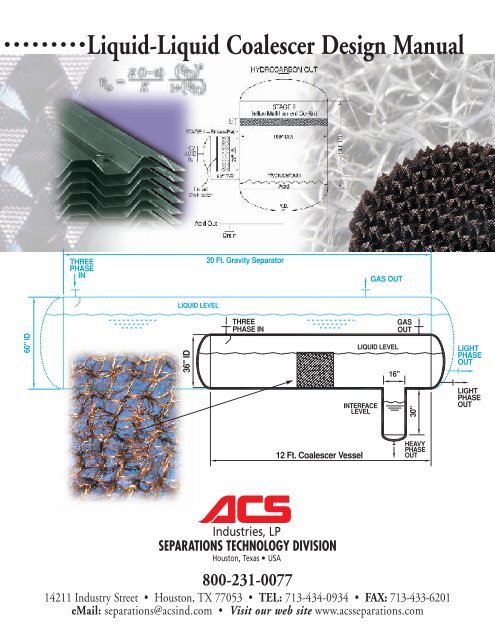
CASE STUDY #2<strong>Coalescer</strong>s in Gas PlantsA major South American engineering company wasdesigning a 100 MMSCFD natural gas plant that usedethylene glycol (EG) for dehydration and for inhibitinghydrate formation. There is a horizontal Three PhaseCold Separator with a boot in this process that does mistelimination in the free board above a large liquid hold-upsection that extends the length of the vessel. The lattervolume is used to recover the glycol that has becomeemulsified as fine droplets in the NGL’s (natural gas liquids)and the dispersed hydrocarbons that have stabilized inthe EG. Since the glycol continually re-circulates in thesystem, fine NGL droplets tend to build up in the inventorycausing an emulsification of both liquid phases. The EGdroplets are thought to be as small as 30 microns in theorganic phase, so 30-minute hold-up times for gravityseparation are not uncommon in the industry. <strong>ACS</strong> wasasked if a coalescer could be provided to significantlyreduce the resultant vessel size.The process conditions for the coalescer sizing was for itto handle 37.5 gpm of NGL’s that had a density of 31lbs/ft3 and a viscosity of 0.11 cp; and 7.5 gpm of 75%ethylene glycol that had a density of 51.1 lbs/ft3 and aviscosity of 7.2 cp. A quick design for a gravity separatorcan be done with equation 2 if the maximum height thata 30-micron glycol droplet would have to fall from the liquidlevel to the boot at the bottom of the vessel is used asif it was the CPI coalescer’s h. In this case 42" wasassumed for a 60" ID vessel. ThusV = 162(45) 42 (.11)(.818-.496)30 2= 215 cubic feetThis means with gravity alone a 5’ dia. x 20’ tangentto tangent vessel would be required. In order to improvecontrol and to allow for disengagement at 10”/min., a16” dia. x 30” tall boot was specified. <strong>ACS</strong> recommendedand supplied a 24" thick mesh coalescer of a co-knit offiberglass yarn and stainless steel wire. The liquid loadingsizing criteria required the installation of a 24" highsegment in a 36" ID vessel. This vessel was 12’ tangentto tangent with the same 16" diameter X 30" tall boot.Thus, as compared to a conventional gravity separator,the use of an engineered coalescer was successful inreducing the vessel volume by a factor of 4.5.An illustration of this is shown on the cover of this bulletin.Gas Product to Pipeline90˚F @1150 PSIGFeed FromGas FieldCompressor70˚FGas-GasExchangerFIGURE 16GAS PLANT WITH JOULES-THOMPSON DEW POINT CONTROL25˚FHydrocarbon VaporFlash TankLeanGlycolJ-T ValveSteamCOLD SEPARATORWITH COALESCERAT 250 PSIGCondensateReboilerLCRich GlycolRichGlycolMake-upEthylene GlycolLean GlycolLean-Rich ExchangerPumpLean GlycolLIQUID-LIQUID COALESCER DESIGN MANUAL 12TEL: 800-231-0077 • FAX: 713-433-6201 • WEB: www.acsseparations.com • EMAIL: separations@acsind.com
CASE STUDY #3<strong>Coalescer</strong>s in Alkylation UnitsA refinery was using a 15-psi mix valve to acid washthe reactor products of their H 2 SO 4 alkylation unit. Thisis done to extract both acidic and neutral ester sideproducts that readily polymerize, reduce acid strength,and cause foaming. A vertical two-stage coalescerdrum with a horizontal boot (Figure 17) follows immediatelyin order to make a clean break between the twoimmiscible phases and lower the free acid concentrationin the hydrocarbon to less than 15 ppm. The firstcoalescer stage in the horizontal section, used toremove the bulk of the acid, is a vertical Stokes-Pakelement, which is preceded by a 20% open perforatedplate liquid distributor. The second stage is a horizontal<strong>ACS</strong> Interceptor-Pak with Teflon ® Multi-FilamentCo-Knit. The inlet section of the large diameter verticalsection removes the fine acid droplets and allowsthem to drain counter-current to the ascending continuoushydrocarbon stream.<strong>Process</strong> conditions were 2480 GPM of alkylate thathad a specific gravity of 0.59 and a viscosity of 0.21 cpwas mixed with 110 GPM of acid (2/1 ratio of recycleto fresh) that had a specific gravity of 1.85 and a viscosityof 25 cp. The mix valve is reported to create anaverage droplet size of approximately 400 microns forthe washing, but also generates a significant amountof fine droplets. Stokes-Pak with horizontal sheetsand 1/2" crimps was chosen to remove 99+% of alldroplets down to about 35 microns. The volume ofcoalescer required was estimated with equation 2:V c = 219 * 2590 * 0.5 * .21 = 38.6 cubic feet(1.85-.59) 35 2Thus a 16" thickness of Alloy 20 Stokes-Pak wasused in the 78" ID X 5’ long horizontal boot.As mentioned above, counter-current flow in the verticalportion of the tower necessitates liquid loads on thecoalescer below 15 gpm/ft 2 (2 ft/min). This required a15’ diameter vertical section. The Teflon Multi-FilamentCo-Knit <strong>Coalescer</strong> was chosen due to corrosive conditionsand the tight residual acid specification.Experience has shown that a 15-ppm spec requiresremoving essentially all droplets down to 15 microns.A Kuwabara hydrodynamic factor for this media of1.251 is found using the data from Table 3. The collectionefficiency of a single Teflon fiber is found whenthis factor and the data above are plugged into equation4 as followsη D = 0.07 (1-.019) (15/21) 2 = 0.01631.251 (1+(15/21))Putting this value in equation 6 givesL = π (.00083") (1-.019)ln (1-.999)-4(0.0163) 0.019= 14.3"Thus a 15" depth of a 15’ diameter Alloy 20/TeflonMulti-Filament Interceptor-Pak <strong>Coalescer</strong> waschosen for the second stage element.HC/ACIDINLiquidDistributorAcid Out15"72" I.D.60" T/SDrainFIGURE 17COALESCER IN ALKYLATION UNITSHYDROCARBON OUTSTAGE 2Teflon Multifilament Co-Knit180" DIA.HydrocarbonAcidV.B.180" T/TLIQUID-LIQUID COALESCER DESIGN MANUAL 13TEL: 800-231-0077 • FAX: 713-433-6201 • WEB: www.acsseparations.com • EMAIL: separations@acsind.com
Case Study #4Oil-Water Separator on a Production PlatformProduced water enters an oil and gas production platformalong with the organics and forms a distinct separatephase after several let downs in pressure through First,Second, and even Third Stage Separators; FWKO (FreeWater Knock Out) Treaters, Test Separators, etc.According to the governing regulations for the Gulf ofMexico all water must be treated to remove oils down to
Case Study # 5Upgrading a Three Phase SeparatorA major refiner in the Central US was reluctant to putany internals in a critical Three Phase Separator, theNaphtha Stripper Overhead Drum of the FCC Unit.However, slugs of water entraining in the hydrocarbonphase’s outlet were continually causing cycling of itstransfer pump which was a high head centrifugal.Water must be injected upstream of an air cooled condenserto dissolve ammonium sulfide. The rate ofinjection had recently been raised 20% due to anincrease in salt forming components in a new slate ofcrudes. Nonetheless, any solution had to be able tooperate over a 30 month turn-around cycle. Anotherproblem was that their engineers did not want to weldto the vessel’s shell since the sour water servicerequired stress relieving.The three phase inlet consisted of 3900 BPD of naphthathat at operating conditions had a specific gravityof 0.82 and a viscosity of 1.6 cp, 1200 BPD of foulwater that had a specific gravity of 0.99 and a viscosityof .55 cp, and 2.2 MMSCFD of Off Gas at 0.1136lbs/ft 3 . <strong>ACS</strong> engineers worked around the constraintsof an existing 60" ID X 15’ T/T separator with a 24"diameter X 36" tall boot that was now undersized (seeFigure 19). Calculations of the gas velocity of 1.8 ft/sshowed that the Normal Liquid Level (NLL) had to beleft at 39" to allow for mist droplets to fall out in the vessel.However, the velocity of water in the boot was20"/minute, double that allowable for oil disengagement(see page 9). Because of this <strong>ACS</strong> recommendedthat the oil/water interface be relocated to the mainhorizontal section of the vessel and that the naphthaoutlet’s internal standpipe with vortex breakers on atee be raised from 6" to 24". This also helped to preventwater droplets coming off the top of the downstreamcoalescer face from entraining into the HC outletnozzle.A Stokes Law analysis of the separator while it wascycling showed that mean and maximum aqueousdroplet sizes were 105 and 350 microns, respectively,as they entered with the naphtha. In order to achievethe specification of
APPROXIMATE RANGES OF APPLICATION FOR VARIOUS COALESCING MEDIAPlate-Pak <strong>Coalescer</strong>Wire MeshInterceptor-Pak Teflon ® FiberInterceptor-Pak FiberglassInterceptor-Pak 125 micron 75 micron 15 micron 7.5 micronHuman hair Mist Fog BacteriaThree-PhaseSeparatorsStaticMixersExtractionColumnsTwo-PhasePump DischargesMixValvesCaustic WashDrumsCondensationin PipelinesAnti-FoamSurfactantStokes-Pak Wire WoolInterceptor-Pak Polyester FiberInterceptor-Pak Fiberglass MatInterceptor-Pak General References:American Petroleum InstitutePublication 421,Design and Operations of Oil-Water Separators, APIRefining Department,Washington, DC, 1990.Gas <strong>Process</strong>ors SuppliersAssociation, Engineering DataBook, Volume 1, 11th Edition,Tulsa, OK, 1998.Hoffmann-La Roche StandardDesign Practice for Decanters(Liquid-Liquid Settlers), Nutley,NJ, 11/84.Holmes, T. L., AIChESymposium Series,77, 211, pp. 40-47, 1981.Lee, K. W. and Liu, B.Y.H.,Journal of the Air PollutionControl Association, 30, 6,4/80.Monnery, W.D. and Svrcek,W.Y., Chemical EngineeringProgress, pp. 29-40, 9/94.Lieberman, N. P.,Troubleshooting <strong>Process</strong>Operations,3rd Edition, PennWell Books,Tulsa, OK, 1991.Mugele, R. A., and Evans, H. D.,Industrial and EngineeringChemistry, 43, 6, 1951.Paragon EngineeringServices, Produced WaterTheory and EquipmentDescription, Houston, TX.Perry’s Chemical Engineer’sHandbook, 6th Edition,McGraw-Hill, New York, NY,1984.Reist, P.C., Aerosol Scienceand Technology, 2nd Edition,McGraw-Hill, New York, NY,1993.<strong>ACS</strong> Industries presents theinformation in this publication ingood faith, believing it to be accurate.However, nothing herein is tobe construed as either an expressor implied guarantee or warrantyregarding the performance, merchantability,fitness, application,suitability, nor any other aspect ofthe products and services of <strong>ACS</strong>Industries, LP. No informationcontained in this bulletin constitutesan invitation to infringe anypatent, whether now issued orissued hereafter. All descriptionsand specifications are subject tochange without notice. Stokes-Pak TM , Interceptor-Pak and Plate-Pak TM are trademarks of <strong>ACS</strong>Industries, LP. Teflon is a registeredtrademark of E. I. Dupont deNemours.
Engineered Excellence!Quick ReplacementGrass Root and Revamp ProjectsMIST ELIMINATORS • <strong>ACS</strong> is the industry leader with 50+years of experience engineering and fabricating mist eliminationproducts. Your only source for MisterMesh ® mesh pads,MultiPocket vanes and AccuFlow inlet distributors. <strong>ACS</strong>offers the quickest replacements of virtually any mesh orchevron mist eliminators with short lead time - stockedinventory from polypropylene to Hastelloy!LIQUID DISTRIBUTORS • Quality fabrication of high performanceand all conventional styles (V-trough, V-notched, tubed,side splash baffles, orifice riser, spray nozzle & pipe lateralfeed) for any range of liquid loading. All high performanceliquid distributors are performance tested with on-site facilitiesprior to shipment.RANDOM PACKINGS • Large inventory of stocked randompackings including metal slotted rings and saddles. Ceramicand plastic varieties also available upon request. Call us foryour emergency needs.INTERNALS • Chimney, transition and liquid drawoff trays, bargrating and multibeam injection packing supports and bed limiters.Broad range of custom internals for distillation, absorption andenvironmental scrubber columns. <strong>ACS</strong> fabricates in exotic metalsas well as plastics.STRUCTURED PACKINGS • All common crimps of sheet metalstructured packings licensed from Montz GmbH (200X, 250Y etc.and high capacity "M" Series). <strong>ACS</strong> is vertically integrated -stocking, drawing, weaving and crimping its own wire. This makes<strong>ACS</strong> the most cost effective supplier of quality <strong>ACS</strong>-BX gauze andGoodloe ® -type packings. Ask about our technique allowingfor shop installation of packing prior to shipment to eliminatecostly field installations!Goodloe ® is a registered trademark of Metex Corporation.FRACTIONATION TRAYS • Round, rectangular, fixed, floatingand caged valve trays, and of course bubble cap, sieve, baffleand rain deck trays. <strong>ACS</strong> offers the FRI tested high efficiencySEMV® floating and fixed valves. <strong>ACS</strong> also offers othernon-proprietary replacement tray hardware for a varietyof trays available in the market.24 7EMERGENCYSERVICEON-SITE ENGINEERING & FABRICATION FOR ALL YOUR VESSEL & TOWER INTERNALS<strong>ACS</strong> Separations & Mass-Transfer Products 14211 Industry Street • Houston • Texas 77053TEL: 800-231-0077 or 713-434-0934 • FAX: 713-433-6201 • WEB: www.acsseparations.com • EMAIL: separations@acsind.com5-2006 • 1500 • AP