The Engineered Mist Eliminator - AMACS Process Tower Internals
The Engineered Mist Eliminator - AMACS Process Tower Internals
The Engineered Mist Eliminator - AMACS Process Tower Internals

You also want an ePaper? Increase the reach of your titles
YUMPU automatically turns print PDFs into web optimized ePapers that Google loves.
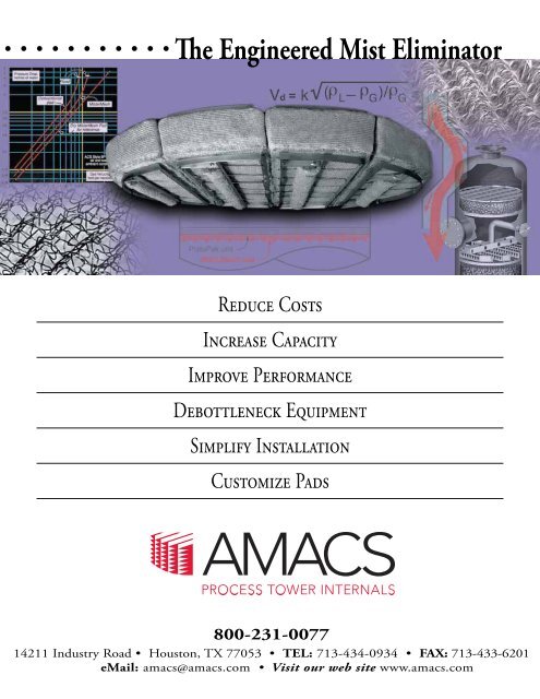
Table of ContentsIntroduction............................. 1Droplet Formation and Size Distributions .... 1Mechanisms of Droplet Removal ........... 2Types of <strong>Mist</strong> <strong>Eliminator</strong> Mesh & Materials ... 4Design Equations ........................ 6Predicting Pressure Drop ................. 7Inlet Diffusers ........................... 7Vessel Configuration ..................... 8Advanced <strong>Mist</strong> <strong>Eliminator</strong> Designs ........ 10Mesh -Vane Assemblies ................. 11Use of Geometry ....................... 11MultiPocket V anes .................... 11Case Studies & Examples ............... 12Plate-Pak and <strong>Mist</strong>Xpert are trademarks of<strong>AMACS</strong>. MaxFlow ® is a registered trademarkof <strong>AMACS</strong> and <strong>Mist</strong>ermesh ® is a registeredtrademark of <strong>AMACS</strong>. Ripple Tray ® is aregistered trademark of Stone & WebsterEngineering Corporation. Kynar ® is a registeredtrademark of ELF Atochem North America, Inc.Teflon ® is a registered trademark of E.I. du Pontde Nemours and Company. Hastelloy ® is aregistered trademark of Haynes International,Inc. Goodloe ® is a registered trademark ofKoch-Glitsch, LP. <strong>AMACS</strong> presents theinformation in this publication in good faith,believing it to be accurate. However, nothingherein is to be construed as an express orimplied warranty or guarantee regardingperformance, merchantability, fitness for aparticular purpose, non-infringement of patents,trademarks or copyrights.©Copyright 2012 by <strong>AMACS</strong>,Printed in USA 4-04 1000AP<strong>The</strong> <strong>Engineered</strong> <strong>Mist</strong> <strong>Eliminator</strong><strong>Mist</strong> elimination, or the removal of entrained liquid droplets from a vaporstream, is one of the most commonly encountered processes regardless ofunit operation. Unfortunately, mist eliminators are often considered commodityitems and are specified without attention to available technologiesand design approaches. <strong>The</strong> engineered mist eliminator may reduce liquidcarryover by a factor of one hundred or more relative to a standard unit, drophead losses by 50% or more, or increase capacity by factors of three or four.This manual summarizes cost effective approaches to reducing solventlosses or emissions, extending equipment life and maintenance cycles -using proven and cost effective technologies and techniques.Droplet Formation and Size DistributionsEntrained liquid does not consist of same-sized droplets, but as a broadrange of droplet sizes that may be characterized with a Normal or BellDistribution centered about some mean or average. <strong>The</strong> average dropletsize depends very much on the mechanism by which they are generated.Sizing equations are expressed in terms of the probability of removing adroplet of a given diameter, and mist eliminator performance is the inte -gration or cumulative sum of individual removal efficiencies. It is thereforecritical to know the approximate droplet size distribution in order toproperly design a mist elimination system. Figure 1 shows some typicalsize distribution curvesFIGURE 1from different sources.VOLUME FRACTION FREQUENCY DISTRIBUTIONSFOR DISPERSIONS OF VARIOUS MATURITIESIn practice, designersor engineers do notquantify or measuredroplet size distributions,rather they areassumed based onempirical data or experience.Fortunately, anexperienced engineercan assume anapproximate distribu -tion based on themeans or mechanismby which the droplets are generated. Typical examples from commonmist sources are given to illustrate these concepts.Fine droplet distributions, often called fogs (
FIGURE 8THEORETICAL EFFICIENCY VS . VELOCITY FOR VARIOUSDROPLET SIZES (WATER IN AIR AT AMBIENT CONDITIONSFOR TYPICAL MESH PADS AND PLATE -PAK UNITS WITHLIGH T LIQUID LOAD)eliminator becomes choked with liquid, a conditioncalled flooding. Flooding is often noticed by high pressuredrops or massive carryover of liquids. Typical wiremesh mist eliminators accommodate liquid loads up toabout one US gallon per square foot and vanes twiceas much.Droplet Capture Ef ficiency, %Gas velocity , feet per second<strong>The</strong> key operating ranges and suitability of mesh andvane mist eliminators are summarized in Figure 9. Itemphasizes that vanes are more effective at highervelocities and greater droplet sizes while mesh is moresuitable for removing smaller particles at lower veloci -ties. Gravity settling alone is sufficient for very largeparticles, and co-knit mesh pads, discussed below, forparticles in the range of sizes from 2-8 µm. Finally, fiber -bed technology is used for submicron fogs.FIGURE 9APPROXIMATE OPERATINGRANGES OF MIST ELIMINATORSA. Burkholz, Droplet Separation,p.2, fig 1-2; VCH Publishers,New York (1989)It is worthwhile to discuss Fig. 8 and mist eliminatorperformance. <strong>The</strong> dotted curves correspond to differentstyles of vanes and the solid to wire mesh styles. Notefirst of all that vanes can be engineered to operate athigher gas velocities and flow rates relative to mesh,but that mesh mist eliminators can approach 100%removal efficiency at smaller droplet sizes. This agreeswith the discussions above on Interception and InertialImpaction removal mechanisms. Note the drastic efficiencydrop off at low velocities, in which droplets driftaround the filaments or vane blades without strikingthem. This phenomenon defines the lower operatingrange of a mist eliminator. <strong>The</strong> other extreme is whenthe velocity is too high. In this case, the droplets arecaptured but the velocity of the gas provides sufficientenergy to tear off and re-entrain droplets. It is in thecontext of re-entrainment that the design equationswhich follow show that the removal efficiency is directlyproportional to the surface tension of the liquid. As thesurface tension increases, so it requires greater kineticenergy (i.e. gas velocity) to break the bond betweendroplet and target, and the droplets collect and coalesceuntil drainage by gravity. Re-entrainment defines theupper capacity limit of a mist eliminator.Operating range is also affected by the liquid loading(proportion of liquid) of the gas. If too great, the mistDroplet Size, micronsGas Velocity, feet per secondP = PlatePakM = MeshC = Co-KnitTypes of <strong>Mist</strong> <strong>Eliminator</strong> Mesh Styles & MaterialsMost designers believe that all wire mesh mist elimi -nators behave basically the same in terms of capacityand removal efficiency. It is true that for meshes ofsame filament diameter, the denser mesh offers supe -rior removal efficiency. For meshes with differing filamentdiameters, a lighter (less dense) mesh may offerconsiderably better removal efficiency. <strong>The</strong> key is thatthe working part of the mesh is the target density, notTHE ENGINEERED MIST ELIMINATOR 4TEL: 800-231-0077 FAX: 713-433-6201 WEB: www.amacs.com EMAIL: amacs@amacs.com
K = K = [( ρL- ρG )Vd 2 ] / 9 µD (2)Where K = dimensionless inertial parameterV = gas velocity in fpsd = Liquid droplet diameter in ftµ = Gas viscosity in lb/ft sD = Wire or filament diameter in ftUse this calculated K value with Figure 10 to find the correspondingvalue of the impaction efficiency fraction E.From Table 1, find S, the specific surface area for themesh style of interest, and determine SO, the area ofthe mist eliminator perpendicular to vapor flow andwith a correction factor of 0.67 to remove that portionof the knitted wire not perpendicular to the gas flow:SO = Specific Surface Area x 1/ π x Thickness (ft) x 0.67Using these values and T, the thickness of the pad, cal -culate the capture efficiency:Efficiency % = 100-(100/e0.213 ESO )Where S0 = Corrected Pad SpecificSurface AreaE = Impaction efficiency fractionThis efficiency is the percent of all incoming droplets ofthe given diameter which will be captured rather thanpassing through the mist eliminator. <strong>The</strong> percentage willbe higher for larger droplets and lower for smaller.FIGURE 10D ETERMINING IMPACTION E FFICIENCYFRACTION E USING INERTIAL PARAMETER K1.00.90.80.70.60.50.40.30.20.1Impaction EfficiencyFraction E0 1.0 10 100Inertial Parameter KPredicting Pressure DropAlthough the operating pressure differential across aproperly sized mesh pad or vane is never more than afew inches of water, pressure drop is an important designconsideration in certain applications, particularly vacuumsystems or larger columns requiring the movement ofgreat quantities of gas. It has been shown that each inchof head loss requires some 0.16 hp/scfm. A simple cor -relation has been developed to describe the pressuredrop through a dry mist eliminator (no mist):∆Pdry = 0.4Vd 2 ρG ST/g c ε ρw (3)Where gc = gravitational constantε = Mesh Void Fractionρw = Ambient water density<strong>The</strong> overall pressure drop is the sum of the head lossincurred as the gas travels through the mesh, as well asthat due to the resistance to captured liquids. Liquidaccumulates as a pool in the bottom of the mist eliminator.If the liquid loading and velocity are such that a 2"deep pool accumulates in the bottom of the mesh pad,this amount must be added to that calculated usingEquation 3. Figure 11 summarizes pressure drop andvelocity test data collected on the <strong>AMACS</strong> pilot plant forlight and medium liquid loading.With due consideration given to the mist eliminator itself,the flow of fluid to and from it requires the same attention.Inlet DiffusersAt high flow rates, primary removal of bulk liquidsupstream of the mist eliminator is very important to pre -vent flooding. This is typically done in a cost effectivemanner by using a simple inlet diverter as shown in Fig. 12.With this design, liquids impinge upon the diverters, theflow is forced to flow laterally to allow bulk liquids toescape by gravity and eliminate the countercurrentmomentum of the gas.<strong>The</strong> Force of Inertia, expressed as ρυ 2 , is typically usedto quantify the flow entering a vessel to determine wheth -er a simple baffle will suffice. <strong>AMACS</strong> recommends inletdiverters to a Force of Inertia up to 2,500 lb/ft s 2 . Abovethis, more sophisticated distributors are recommended.THE ENGINEERED MIST ELIMINATOR 7TEL: 800-231-0077 FAX: 713-433-6201 WEB: www.amacs.com EMAIL: amacs@amacs.com
FIGURE 11ACTUAL PRESSURE DROP VERSUS VELOCITY FOR TYPICAL <strong>AMACS</strong> MESH PADS AT LIGHT AND MEDIUM LOADS<strong>AMACS</strong> Style 4BA, 4 inches thick<strong>AMACS</strong> Style 4CA, 4 inches thickPressure Drop, inches of waterGas velocity , feet per secondDecades ago, Dutch Shell Chemical Company intro -duced Schoepentoeter ®style bladed designs (Fig. 12). AsFIGURE 12the fluid flows axiallytowards the shellopposite of the inletnozzle, liquids arecaptured by speciallyplaced blades.This design is supe -rior because itallows the escape ofliquids over a muchgreater region of thevessel. A simple inlet diverter ( Fig. 13) would simplyshear bulk liquids into smaller droplets at great flowrates:<strong>AMACS</strong> AccuFlowInlet Diffuser (Fig.14) is an adaption ofthe bladed designsin which the body ofthe diffuser maintainsits shape, the restrictionof flow whichallows the escape ofFIGURE 13liquids over thediameter of the vesselis accomplishedusing internal bladesof concentric anddecreasing crosssectionalareas.FIGURE 14Vessel ConfigurationSeveral factors must be considered when deciding onthe configuration of vessel internals. <strong>The</strong> first step is todetermine the cross-sectional area needed. <strong>The</strong>n a ten -tative geometry and shape appropriate for both the ves -sel and plant location is selected. Figure 15 shows themost typical, but by no means complete, configurations.<strong>Mist</strong> eliminators can be of virtually any size or shape toaccommodate all factors.<strong>The</strong> performance of the mist eliminator depends strongly onan even velocity distribution over the cross-sectional area.As a general rule, a distance of either half the vessel diameteror 72", whichever is smaller, is sufficient spacing bothupstream and downstream of the element. Representationsfor specific cases are illustrated in Figure 16.THE ENGINEERED MIST ELIMINATOR 8TEL: 800-231-0077 FAX: 713-433-6201 WEB: www.amacs.com EMAIL: amacs@amacs.com
FIGURE 15SIMPLIFIED VIEWS OF TYPICAL MIST ELIMINATOR CONFIGURATIONS IN SEPARATORVESSELSSmall velocity differences are acceptable, but should beminimized at the design stage. Otherwise, some regionsof the mist eliminator may be subjected to heavy loadingleading to re-entrainment while other regions are unused.Most often, the mist eliminator is located just upstreamof the outlet nozzle with insufficient disengagementspace. Vapor tends to channel through the pad in theregion closest to the outlet nozzle and peripheral regionsof the pad remain unused. To rectify this, <strong>AMACS</strong> engi -neers apply an Integral Flow Distributor which is weldedto region(s) of the downstream face of the pad. Thistechnique allows the engineer to selectively increase thepressure drop through regions of the pad likely to sufferfrom channeling, and is cost effective.THE ENGINEERED MIST ELIMINATOR 9TEL: 800-231-0077 FAX: 713-433-6201 WEB: www.amacs.com EMAIL: amacs@amacs.com
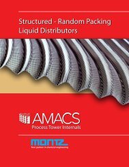
Advanced <strong>Mist</strong> <strong>Eliminator</strong> Designs<strong>The</strong>re are several modifications to mesh pads andvanes to dramatically enhance performance.FIGURE 16Guidelines for maintaining even flow distribution acrossmesh pads or vane units with axial flow in cylindrical vessels.Height of vessel head is assumed to be 1/4 of vesseldiameter. Flow distribution devices can minimize requireddisengagement space above mesh pads.Contact <strong>AMACS</strong> for assistance.Drainage & Collection LayeringRecall the discussion on pressure drop through a misteliminator in which liquid tends to pool in the lower layersof mesh. <strong>The</strong> simplest technique to promote drainage isto use a few inches of open, porous mesh such as<strong>AMACS</strong> style 7CA (5-lb density with specific surface areaas low as 45 sq-ft/cu-ft) in the upstream position. Asdrainage occurs through the interstitial regions of theFIGURE 17mesh, opening theknit enhances liquiddrainage.An extension of thisapproach is to usehigher specific surfacearea mesh in down -stream positions toenhance separationefficiency, with inter -mediate mesh between the collection and drainagezones. Figure 17 illustrates a Multilayer mist eliminator.<strong>Mist</strong>erMesh ® Drainage RollsA second technique used by <strong>AMACS</strong> to enhance liquiddrainage, and often in conjunction with multi-layering,is to append drainage coils to the upstream face of ahorizontal mist eliminator as shown in Figure 18.<strong>The</strong> rolls are also made of mesh and "fill" with liquid.FIGURE 18High removalEf ficiency LayerIntermediateLayerDrainage Layer ,Open PorousMeshMISTER MESH PAD WITH DRAINAG E ROLLSOnce filled, liquid from the pad above is drawn through,surface tension affects to the coils, thereby establishingdistinct regions for liquid drainage and liquid collection inthe upstream layers. Figure 18 compares the pressuredrop and flooding point of both conventional and<strong>Mist</strong>erMesh ®<strong>Mist</strong> <strong>Eliminator</strong>s.THE ENGINEERED MIST ELIMINATOR 10TEL: 800-231-0077 FAX: 713-433-6201 WEB: www.amacs.com EMAIL: amacs@amacs.com
Mesh-Vane AssembliesIn grass root design of larger vessels and of existingones to accommodate greater rates, mesh-vaneassemblies are often used. In an assembly, mesh isplaced upstream of the vane and acts as aagglomerator. <strong>The</strong> Capacity Factor used corresponds tothe downstream vane element. This approach combinesthe e ciency of mesh with the capacity of vanes and hasbeen used by <strong>AMACS</strong> engineers with tremendous suc -cess over the past two decades.FIGURE 19ACTUAL PRESSURE - DROP PERFORMANCEOF MESH PADS VERSUS VELOCITY .NOTE RAPID INCREASE AS FLOODEDCONDITION IS APPROACHEDin Figure 19 for smaller and larger diameters. An <strong>AMACS</strong>engineer should be consulted for such designs.Up to36"FIGURE 2072" and LargerUp to72"Pressure Drop, inches of water<strong>Mist</strong>erMeshDry <strong>Mist</strong>erMesh Padfor referenceGas velocity, feet per second<strong>AMACS</strong> Style 8 P mesh,air & water , ambientconditions .Throughout the industry there is ongoing debate as towhether the mesh should be positioned up - or downstreamof the vane element. Engineers at <strong>AMACS</strong> haveperformed exhaustive comparative testing on pilot plantsand have much date proving that the mesh is indeede ective upstream of the vane, unless the vane elementis used as a to protect a downstream mesh pad.MultiPocket Vanes<strong>The</strong> capacity of vertical vanes (with horizontal vaporow) can also be increased by enhancing liquiddrainage. As discussed, captured liquids are re-entrainedwhen the velocity of vapor exceeds the ideal. Toprevent liquid re-entrainment, the serpentine patho ered by the vane is augmented with obstructions toallow for the pooling of liquid with protection from thepassing vapor stream. This design increases thecapacity of the vane by as much as 45%. In verticalgas compressor knock-out drums, in which the vesselsize is dictated by the capacity of the mist eliminator,MultiPocket Vanes FIGURE 21considerably reducethe footprint and costof skids.Figure 21 summarizesthe approaches usedby <strong>AMACS</strong> and thereduction in vesseldimensions possibleusing these advanceddesigns.Use of GeometryAnother approach used in the industry when the size ofthe vessel is limited is to arrange the mist eliminator atan angle. <strong>The</strong> capacity increase is equal to the sine ofthe angle though it should not exceed 45˚. This is shownTHE ENGINEERED MIST ELIMINATOR 11TEL: 800-231-0077 • FAX: 713-433-6201 • WEB: www.amacs.com • EMAIL: amacs@amacs.com
Conventionalhorizontal padFIGURE 22APPLYING COMBINATIONS OF <strong>AMACS</strong> MESH PADSAND PLATEPAK VANE UNITS TO MINIMIZE VESSEL SIZECASE STUDIES & EXAMPLESProblem: In an HCl scrubber, an air stream of 60 acfs iscoming off a bed of random packing and contains drop -lets of a weak acid. <strong>The</strong> unit operates at 122 psia at 82˚F.Determine the size of mist eliminator required to removethis mist and the removal efficiency possible.Solution: Since the acid is dilute we assume the densityand viscosity of water at the operating pressure and temperature:<strong>Mist</strong>erMesh pad<strong>Mist</strong>erMeshpad and PlatePak unitPlatePak Uni t<strong>Mist</strong>erMesh PadρL = 62.4 lb/ft 3ρG = 0.60 lb/ft 3P = 122 lb/ft 2T = 82˚FF = 60 ft 3 /s<strong>The</strong> first step is to select the mist eliminator type andmesh style. As shown in Figure 2, mist coming off the topof packing is typically comprised of droplets ranging insize from as small as 5 µm, so we select a mesh stylemist eliminator to achieve this level of performance.From experience, the capacity factor for poly mesh atmoderate liquid loading and lower pressures is ~.27 fps.Using the Souders-Brown equation the ideal velocity iscalculated:Videal = k [ (ρL- ρG ) / ρG ] 1/2Videal = 0.27[(62.4-.060)/0.60] 1/2Videal = 3.55 fps<strong>The</strong> cross-sectional area of mist eliminator is determinedby dividing the volumetric flow rate by the ideal velocity:A rea <strong>Mist</strong> <strong>Eliminator</strong> = Volumetric Flow Rate/Superficial Vapor VelocityArea <strong>Mist</strong> <strong>Eliminator</strong> = [60 ft3/s]/3.55 fps= 16.9 ft2Area <strong>Mist</strong> <strong>Eliminator</strong><strong>The</strong> corresponding diameter is 55.67", rounded up to astandard 60" scrubber vessel. Note that performing thesame calculations using a vane (and a Capacity Factorof 0.50) yields an ideal vessel diameter of 46.57", roundedup to a standard 48" ID vessel. To calculate theremoval efficiency at 5 µm, several parameters must beidentified to use equation 2 to determine the inertialparameter K:THE ENGINEERED MIST ELIMINATOR 12TEL: 800-231-0077 FAX: 713-433-6201 WEB: www.amacs.com EMAIL: amacs@amacs.com
K = [( ρL- ρG )Vd 2 ]/9µDK = 0.54From Figure 10, the corresponding Impaction E ciencyFraction E is ~0.15. In the Removal E ciency Equationthere is a term for the corrected surface areaSO:SO =Surface Area x 1/π xThickness (ft) x 0.67For <strong>AMACS</strong> style 8P, the surface area is(185 + 36) = 221 ft 2/ft 3 , we will try both 4" and 6" thickmist eliminator thicknesses (1/3 and 1/2ft):SO = 221 x 1/3.14 x 1/3 x 0.67SO 4"thick = 15.7 and SO 6"thick = 23.6And RemovalE at 5 µm is:= 100 – 100/e ESO= 100 – 100/e(0.15)(15.7)= 90.5%For the 6" thick element, the removal e ciency is 97.1%.By using a composite pad containing a 2" layer of regularpolypropylene, style 8P, upstream of a 2"thick layer of 8PP, mono- andco-knit, theremoval e ciency is 99.9% .CASE STUDY #2Traditionally, trays are used to bring about contactbetween glycol and natural gas in dehydration contactors.In recent years, the industry moved towards smallerdiameter columns by exploiting the higher capacitiesachieved with structured packing. However, the lowercapital investment associated with a smaller diameterpacked tower is often o set by dramatically increasedglycol losses.Consider a mid-western sour gas plant operating a 96"glycol contactor and processing 1,310,000 lb/hr of gas at116˚F and 1214 psia. <strong>The</strong> gas and liquid densitieswere 4.4 and 68 lb/cu-ft respectively. <strong>The</strong> plant wasexperiencing 0.13 US gal of carryover per mmscf,amounting to some 65 gal/day of lost triethylene glycol,several hundred dollars worth per day. A 10" thick wiremesh mist eliminator of 12-lb mass density was installedabove the packing.From experience, <strong>AMACS</strong> engineers knew that the dropletsize distribution for glycol coming o the top of apacked dehydrator extends down to diameters of 5 µmand greater. Also, if the diameter of the packed columnwas sized in accordance with the hydraulic requirementsof the packing, the wire mesh mist eliminator would beundersized.<strong>The</strong> capacity factor for 12-lb density mesh in this serviceis ~0.23 – 0.27, having been de-rated for the high liquidviscosity of 18 cP (which retards liquid drainage) andrelatively high operating pressure. Using the gas density,volumetric rate and cross-sectional area of the misteliminator, the actual velocity is readily calcu -lated. Next, using known densities of the gas and glycol,the actual or operating Capacity Factor k is determined:Vactual = k actual [(ρL- ρG ) / ρG ] 1/2Re-arranging fork actual = V actual / [(ρL- ρG ) / ρG ] 1/2= 0.44 fpsA Capacity Factor of 0.44 fps is almost twice as highas the optimum, and is in the range of that of an <strong>AMACS</strong>PlatePak Vane mist eliminator. However, the vanewill not remove particles down to 5 µm, so a meshvaneassembly was proposed. <strong>The</strong> assembly has amultilayered mesh section with open, porous mesh(<strong>AMACS</strong> style 7CA). Upstream of high surfaceare 8D(T) co-knit of stainless and Dacron ® . <strong>Mist</strong>erMesh ®drainage rolls were appended to the bottom face of themist eliminator. Downstream of the mesh was placed aPlatePak Vane. <strong>The</strong> total thickness was 12" and wasaccommodated using the same supports as the misteliminator it replaced.Carryover from a glycol contactor occurs through twomechanisms, evaporative losses and mechanical (carryoverlosses). In this example, simulations showedevaporative glycol losses of 0.0054 gal/mmscfd. <strong>The</strong>total losses after the revamp were less than 0.008 gal/mmscfd, and carryover losses had been reduced from0.13 gal/mmscfd, a 94% reduction!THE ENGINEERED MIST ELIMINATOR 13TEL: 800-231-0077 • FAX: 713-433-6201 • WEB: www.amacs.com • EMAIL: amacs@amacs.com