The Engineered Mist Eliminator - AMACS Process Tower Internals
The Engineered Mist Eliminator - AMACS Process Tower Internals
The Engineered Mist Eliminator - AMACS Process Tower Internals

You also want an ePaper? Increase the reach of your titles
YUMPU automatically turns print PDFs into web optimized ePapers that Google loves.
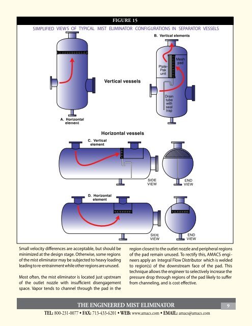
FIGURE 15SIMPLIFIED VIEWS OF TYPICAL MIST ELIMINATOR CONFIGURATIONS IN SEPARATORVESSELSSmall velocity differences are acceptable, but should beminimized at the design stage. Otherwise, some regionsof the mist eliminator may be subjected to heavy loadingleading to re-entrainment while other regions are unused.Most often, the mist eliminator is located just upstreamof the outlet nozzle with insufficient disengagementspace. Vapor tends to channel through the pad in theregion closest to the outlet nozzle and peripheral regionsof the pad remain unused. To rectify this, <strong>AMACS</strong> engi -neers apply an Integral Flow Distributor which is weldedto region(s) of the downstream face of the pad. Thistechnique allows the engineer to selectively increase thepressure drop through regions of the pad likely to sufferfrom channeling, and is cost effective.THE ENGINEERED MIST ELIMINATOR 9TEL: 800-231-0077 FAX: 713-433-6201 WEB: www.amacs.com EMAIL: amacs@amacs.com