Compressor Suction Drums: - AMACS Process Tower Internals
Compressor Suction Drums: - AMACS Process Tower Internals
Compressor Suction Drums: - AMACS Process Tower Internals
- No tags were found...

You also want an ePaper? Increase the reach of your titles
YUMPU automatically turns print PDFs into web optimized ePapers that Google loves.
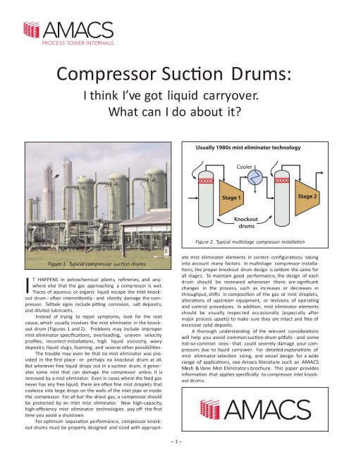
<strong>Compressor</strong> <strong>Suction</strong> <strong>Drums</strong>:I think I’ve got liquid carryover.What can I do about it?Usually 1980s mist eliminator technologyCoolerStage 1 Stage 2KnockoutdrumsFigure 2. TypicalcompressorFigure 1. Typical compressor drumsIT HAPPENS in petrochemical plants, refineries, and anywhereelse that the gas approaching a comp ressor is wet.Traces of aqueous or organic liquid escape the inlet knockoutdrum - often intermittently - and silently damage the compressor.Telltale signs include pitting corrosion, salt deposit s,and diluted lubricants.Instead of trying to repair symptoms, look for the rootcause, which usually involves the mist eliminator in the knockoutdrum (Figu res 1 and 2). Problems may include impropermist eliminator specifications, overloading, uneven velocityprofiles, incorrect installations, high liquid viscosity, waxydeposit s, liquid slug s, foaming, and several other possibilities.The trouble may even be that no mist eliminator was providedin the first place - or perhaps no knockout drum at all.But wherever free liquid drops out in a suction drum, it generatessome mist that can damage the compressor unless it isremoved by a mist eliminator. Even in cases where the feed gasnever has any free liquid, there are often fine mist droplets thatcoalesce into large drops on the walls of the inlet pipe or insidethe compressor. For all but the driest gas, a compressor shouldbe protected by an inlet mist eliminator. New high-capacity,high-efficiency mist eliminator technologies pay off the firstyou avoid a shutdown.For optimum separation performance, compressor knockoutdrums must be properly designed and sized with appropriatemist eliminator elements in correct configur s, takinginto account many factors. In multistage compressor installas,the proper knockout drum design is seldom the same forall stages. To maintain good performance, the design of eachdrum should be reviewed whenever there are significan tchanges in the process, such as increases or decreases inthroughput, shifts in composition of the gas or mist droplets,alterations of upstream equipment, or revisions of operatingand control procedures. In mist eliminator elementsshould be visually inspec ted occasionally (especially aftermajor process upsets) to make sure they are intact and free ofexcessive solid deposits.A thorough understanding of the relevant considerwill help you avoid common suction-drum pitfalls - and somenot-so-common ones - that could severely damage your compressorsdue to liquid carryover. For detailed explanations ofmist eliminator selection sizing, and vessel design for a widerange of applications, see Amacs literature such as <strong>AMACS</strong>Mesh & Vane Mist Eliminators brochure. This paper providesinfor that applies specifically to compressor inlet knockoutdrums.– 1 –
Designing for droplet size distrThere are many different types of mist eliminator elements,and the variety has greatly increased through the years. Notunderstanding the liquid source in the upstream process cancause you to select the wrong type of mist eliminator, or to keepa given type when process changes make it inappropriate.Understanding the process allows you to design for themost efficient mist Most important, shouldnot be made the droplet size dist is defined, interms of the propo of droplets of each size. Assuming anincorrect droplet size dist can mean that you havedesigned for a less efficient mist eliminator, and liquid carryovermay occur.Table 1.Diameter range of mist and other droplets-Par Type Size range (microns)-Large organic molecule s Up to 0.004 µmSmoke 0.0045 to 1.0 µmC fog 0.1 to 30 µmAtmosphe ric clouds and fog 4 to 50 µmGenerated by gas nozzle 1 to 500 µmAtmospheric “mist” 50 to 100 µmAtmospheric “drizzle” 10 to 400 µmGenerated by boiling liquid 20 to 1,000 µmGenerated by 2-phase flow in pipes 10 to 2,000 µmAtmosphe ric raindrops 400 to 4,000 µmTable 2. Droplet sizes (water in air) typically captured with99.9% efficiency by mist eliminator elements of various typesElement type-Size range (microns)-Fiber candles or panels0.1 and largerMesh with co-knit yarn2.0 µm and larger0.006-inch mesh 5.0 µm and larger0.011-inch mesh 10 µm and largerAmistco double-pocket vane 10 µm and largerC vane arrays 15 µm and largerSee Tables 1 and 2 for some points of reference and roughguidelines in this respect. Be aware that the capture efficiency ofa given mist eliminator element does not depend only ondroplet size. It is also influenced by gas velocity through the elementand mist load in terms of liquid flow rate per unit of crossarea.Then there are variables such as density and viscositythat depend on temperature, pressure, and liquid and gasAll else being equal, efficiency generally goes upwith higher velocity, finer mesh strands, closer packing of mesh(greater density), closer spacing of vanes, and greater thicknessof the mist eliminator element.Mesh pad foulingIn some cases, liquid carryover to the compressor is causedby fouling of a mesh-type mist eliminator, on account of ther of gas flow and extra holdup of liquid in thepad. Vane-type mist eliminators are choice for foulings Due to the wide open spaces betweenblades, vanes are much less likely to plug. If the fouling depositcan be readily dissolved by a suitable solvent, as might be thecase with viscous oils or waxes or certain caked solids, considerinstalling a spray system as shown in Figure 3 to clean the vaneson-line whenever necessary. Adding a high-efficiency meshmist eliminator downstream of the vane unit (also shown inFigure 3) can help make up for the inherently lower droplet captureefficiency of the vanes.Mist-free gasMESH PADVANE UNITGaswithmistTypical mist eliminators for reference:vane unit (above)larger mesh pad (below)Figure 3. spray system to remove depositsLiquid slugs and high liquid loadingIn soms, liquid slugs occasionally come in withthe gas feed. These surges can temporarily overwhelm the slugcatchingcapability of the inlet knockout drum and flood a meshtypemist eliminator, causing liquid carryover. (See Figure 4.)Thin floodedlayer acrosspadcapturing mistand drainingdry zone,flooded zone,agitated byrising gasLargere-entraineddroplets beginto escape padhigher inpadis floodedandagitatedMost capturedmist is blownaway asre-entrainmentliquiddrainsbelowlight liquid loadHigher velocity and load:re-entrainment beginsFigure 4. Envisioning mesh pad performance deg as liquid and gas loads increase (ve– 2 –Excessive velocity and load:flooding, full re-entrainment
Figure 5. Cyclone device to break inlet foamWhen liquid slugs or generally high liquid loading areexpected, it is recommended to use a vane-type mist eliminatorupstream of the mesh pad as shown before in Figure 3. Vanes cangenerally handle up to 10 times more liquid load than mesh pads.Breaking inlet foamIf liquid in the gas approaching the compressor knockoutdrum is subject to foaming, it can readily flood a mesh pad andin severe cases even a vane unit. The end result is massive liquidcarryover from the vessel and damage to the compressor. Avortex-tube cyclone device (Figure 5) can break up foam in theincoming feed.Dealing with high liquid viscosityThere are applications in which high viscosity impedes liquiddrainage so severely that a mesh pad would flood at prohiblowvelocities and liquid loading. In these applications, aitivelyvane unit is the better choice. For high efficiencies, consider<strong>AMACS</strong> multi-pocket vane, s which handle high-viscosityliquids with an efficiency of 99.9% for 8-micron and largerdroplets.Mist eliminator spacing in the vesselAn often overlooked but very important aspect of suctiondrum design that can lead to liquid carryover is proper spacingin the vessel. Figure 6 illustrates guidelines for sufficient distancebetween the mist eliminator and the gas inlet and outlet.If spacing is too close, the gas will pass though only part ofthe mist eliminator. This causes localized high velocities withFigure 6. Generally accepted spacing guidelines to maintain even velocity profileand avoid entrainment in compressor drums with axial flow– 3 –
liquid re-entrainment and low with poor efficiency asshown in Figure 7.In andrum where the mist eliminatoris too close to the gas outlet, there may not be enough roomto lower the mist eliminator. The then might be aproperly designed flow distr device located above themist eliminator to create a more uniform velocity profile.Figure 7. Example of mist eliminator performancedegr due to uneven velocity profileOvercoming pressure-drop constraints<strong>Process</strong>es that operate under vacuum or very low pressureimmediately upstream of the compressor can be very tricky fordrum design, because the pressure drop across the misteliminator must be kept low. However, generally speaking, thelower the pressure-drop character of a mist eliminatortype, the lower its efficiency in removing mist. Liquid carryoverfrom the drum may be a result of a low-efficiencymist eliminator for the sake of low pressure drop.When high efficiency is not required, a vane unit or lowdensitymesh pad may be recommended to achieve low pressuredrop. To gain higher efficiency without much cost in termsof pressure drop, a possible is a dual-density meshpad. In such a pad, the downstream layer has higher densitythan the upstream layer. The result is higher separ efficiencywith only slight increase in pressure drop.When a knockout drum’s throughput has grown to exceedits capacity, there are generally two1. Replace the vessel with a larger one to allow a mist eliminatorwith greater cr area, thus reducing thevelocity.2. Replace the mist eliminator in the vessel withone using the latest technology to maintain efficiencywith higher throughput.O 2 is generally much more anddoes not require pr down e. In a tr vercylindrical vessel, the tr horizontal or is nolonger the only <strong>Compressor</strong> knockout drums can beretr for capacity increases using any of the followingtechniques:1. Ver mist eliminator elements with horizontal flow (K= 0.42 for mesh pads, K = 0.65 for vane units)2. Properly engineered baffling for even velocity profileswith close spacing3. Horizontal mesh pads with drainage layers orzones that can increase capacity by 10 to 12% (K = 0.40)4. Amistco Double-Pocket Vanes that can double the capacityof a vane unit (K = 0.8 to 1.1)5. Mesh-vane that can increase efficiencyand capacity by 10% to 25% (K = 0.5 to 0.65)6. Mesh agglomerator followed by Double-Pocket Vanes forhighest efficiency (99.9% of 2-micron droplets) and greatestcapacity increase7. Two-bank or four-bank configur that allow misteliminator elements of greater cr areasFigure 8 illustrates several of thesehorizontalflow through ver mist eliminator elements, use of meshpads to agglomerate fine mist into large droplets that areremoved by vane units, and a double-bank configura on.Amistco’s design specialists can help apply such advancedmeans ofthe efficiency and capacity ofknockout drums to create o al for par culars.For highest efficiency:<strong>AMACS</strong> Multi-PocketVane unitThroughput exceeding design capacityIn designing compressor knockout drums, like other gasliquidseparator vessels,mist eliminators are generallyselected and sized with a margin of about 10% above thedesign throughput. Flow rates beyond the upper operlimit may allow liquid carryover due to highthatcause re-entrainment from the mist eliminator element.More specifically, mist eliminators are typically sized forcr area to achieve a design velocity according tothe Souders-Brown vapor load factor K:K = V G/ ( – L G )/ GV G= Gas velocity (volume flow divided by crL= Liquid densityG= Gas densityC horizontal mesh pads are tr sizedfor a K factor of 0.35 feet per second, which corresponds to avelocity of 10 feet per second in the reference case of water andair at room s.Figure 8. Typical retrofit of a compressor drum thatmore than doubles its capacity over that of the originalhorizontal mesh pad– 4 –
Retrofit without recertifying for ASME codeRetrofitting an existing vessel for any of the foregoing suggestedremedies has one drawback: it often requires weldingnew support rings, beams, clips and other structures to the vesselwall. Most vessels are ASME code certified. Thus, after weldingto the vessel wall, the welded area must be heat-treated, andthe vessel must be recertified. It is generally desirable to avoidthis cumbersome procedure. <strong>AMACS</strong> offers expansion ringsthat are made in sections that can be passed through a manway.(See Figure 9.)The rings are then bolted together and wedged against thevessel wall without welding. The unique double expansiondesign ensures that the installed ring does not move duringoperation. Once the rings are installed - either in vertical orhorizontal vessels - beams can be bolted to the rings and completehousings can be built up inside the vessel.LowefficiencyMESH PADRe-entrainmentReentrainFigure 10. Typical results of poor flow distribution from theinlet to a compressor knockout drumFigure 9. <strong>AMACS</strong> expansion rings for retrofittingknockout drum internals without weldingUsing inlet diffusers to relieve carryoverInlet design is one of the most commonly neglectedaspects of a compressor knockout drum design, thus often thecause of poor performance. In the example shown in Figure 10;a half-pipe inlet deflector projecting into the vessel reduces thegas flow area of that position, with the following results:1. Gas jets to the back wall of the vessel.2. Without enough space to diffuse the jet, gas utilizes onlypart of the mist eliminator. Due to uneven velocity profile,liquid carryover occurs as in Figure 7.3. The gas jet agitates the accumulated liquid below, generatingdroplets.4. Turbulence spoils normal gravity settling of larger liquiddroplets below the mist eliminator. Additional liquidload increases the likelihood of flooding the mist eliminator.A properly selected inlet diffuser added to an existingknockout drum (Figure 11) provides more effective separationof liquid coming in with the gas and distributes the gas evenlythroughout the vessel diameter before the gas moves upwards.Damage by sudden pressure changesCarefully review the transient pressures that occur at theknockout drum and mist eliminator during all phases of operations.The suction drum could see a sudden surge of flow ineither direction due to compressor recycle or opening an antisurgevalve. Thus, a mesh-type mist eliminator can besubjected to forces not seen in normal operation. This can dislodgethe pad sections, leading to compressor damage from liquidcarryover or even from fragments of the pad.Plan view of inlet diffuserFigure 11. Use of an inlet diffuser to alleviatepoor distribution of inlet flow– 5 –
Pads and vanes can also be damaged by freezing liquids incold climates. In natural gas production and pipelining,hydrate formation is known to destroy mesh pads and vanes.To cope with any of these scenarios, as shown in Figu re 12,any or all of the following remedies can be applied to mist eliminatorelements:1. Reinforce with heavy-duty material.2. Fasten with bolts instead of traditional tie wires, or providean upper suppo rt ring in addition to the lower one.4. Provide a pressure relief door in the case of mesh.Dual supportringsRelief doorThrough boltsFertilizer plant capacity boost & amine loss cutA 4-train fertilizer plant needed more ammonia gas processingcapacity in one of the trains to increase productioncapacity. The bottleneck was the overhead knockout drum intwo of four carbon dioxide absorber towers in that train. Thosevessels also served as suction drums for the comp ressors thatfollowed. In addition, it was desired to r educe excessive loss ofvaluable amine in the form of mist escaping the knockoutdrums.On reviewing the absorber process conditions itwas discovered that the available space in one of the drums wasvery tight, we were able to solve this problem by retrofitting bothdrums with a double-bank system as in Figu re 8. In each bank,a mesh agglomerator is followed by an <strong>AMACS</strong> Multi-PocketVane unit. The result was a 30% capacity increase. In addition,the rate of amine loss fell to 0.05 gallon per million standardcubic feet, which corresponds to savings on the order of $75,000per year. Another benefit was elimination of a cause of pittingcorrosion in the comp ressors.Gas production & condensate recovery increaseA large oil and gas company wanted to revamp severaldozen of their 30-year-old two-phase field separ ators (sizes 2 to5 feet OD). The purpose was to increase capacity and improverecovery of condensate. As in the preceding case, the separatorswere also suction drums for comp ressors.As part of a joint venture with a local fabrication shop, wemoved the units from the field removed the old internals,enlarged the inlet and outlet nozzles, and retrofitted thevessels with Multi-Pocket Vane units. The separators were ASMEcoderecertified painted, and reinstalled in the field with newinstrumentation. This rejuvenation saved the company thousandsof dollars per unit as compa red to purchasing new separators.Gas capacity increased by up to 50%, and condensaterecovery went up by many thousands of barrels per year.Figure 12. Protecting mesh pads from pressure damage<strong>Compressor</strong> knockout drum casesEthylene plant debottleneckA large ethylene producer needed to debottleneck its sixstagecomp ressor train to increase throughout. This projectneeded to be accomplished with minimal cost and down time.Using conventional mist eliminators - mesh pads or horizontal-flowvanes - the knockout drum before each comp ressorstage would have to be enlarged. For instance, the drum at theinlet to the first stage, eight feet in diameter, would be replacedby a 14-foot vessel.After thoroughly reviewing the process conditions andinternal geometry of each knockout drum. We then customi zedeach existing drum with double-pocket v anes and meshagglomerators arranged as in Figu re 8, using on e, two, or fourbanks as required. To ensure proper gas distribution, we addedinlet diffusers as in Figu re 11 and flow distribution plates on thedownstream side of the vane units. The result was 35%increased capacity while achieving an efficiency of 99.9% of 1-micron and larger mist droplets.THESE CASES are typical of many applications whereour separation technology has made a big difference.Similar results can be achieved for a wide variety of compressorknockout drums in refineries, gas plants, oil and gasexploration and production, and petrochemical plants.14211 Industry Street • Houston, Texas 77053Phone 281-331-5956 • Fax 281-585-1780amacs@amacs.com • www.amistco.com24-hour Emergency Service: 800-839-6374<strong>AMACS</strong> has endeavored to assure that all information in this publication is accurate. However, nothing herein is intended as a guarantee or warranty.– 6 –