Mesh and Vane Mist Eliminator Brochure - AMACS Process Tower ...
Mesh and Vane Mist Eliminator Brochure - AMACS Process Tower ...
Mesh and Vane Mist Eliminator Brochure - AMACS Process Tower ...

Create successful ePaper yourself
Turn your PDF publications into a flip-book with our unique Google optimized e-Paper software.
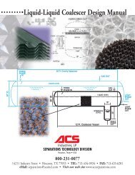
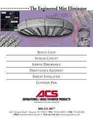
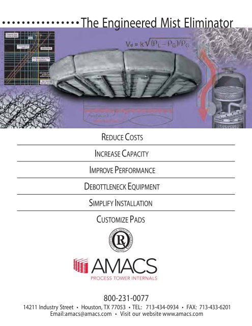
The Engineered <strong>Mist</strong> <strong>Eliminator</strong><br />
REDUCE COSTS<br />
INCREASE CAPACITY<br />
IMPROVE PERFORMANCE<br />
DEBOTTLENECK EQUIPMENT<br />
SIMPLIFY INSTALLATION<br />
CUSTOMIZE PADS<br />
800-231-0077<br />
14211 Industry Street • Houston, TX 77053 • TEL: 713-434-0934 • FAX: 713-433-6201<br />
Email:amacs@amacs.com • Visit our website www.amacs.com
Table of Contents<br />
Introduction ............................ .1<br />
Droplet Formation <strong>and</strong> Size Distributions ... .1<br />
Mechanisms of Droplet Removal .......... .2<br />
Types of <strong>Mist</strong> <strong>Eliminator</strong> <strong>Mesh</strong> & Materials . . .4<br />
Design Equations ....................... .6<br />
Predicting Pressure Drop ................ .7<br />
Inlet Diffusers .......................... .7<br />
Vessel Configuration .................... .8<br />
Advanced <strong>Mist</strong> <strong>Eliminator</strong> Designs ....... .10<br />
<strong>Mesh</strong>-<strong>Vane</strong> Assemblies ................. .11<br />
Use of Geometry ...................... .11<br />
MultiPocket ® <strong>Vane</strong>s .................... .11<br />
History of ACS Industries, Inc. ........... .12<br />
MaxCap TM <strong>Mist</strong> <strong>Eliminator</strong> ............... .14<br />
Case Studies & Examples .............. .15<br />
Plate-Pak <strong>and</strong> AccuFlow are trademarks<br />
of <strong>AMACS</strong> <strong>Process</strong> <strong>Tower</strong><br />
Internals. <strong>Mist</strong>er<strong>Mesh</strong> ® <strong>and</strong> MultiPocket ®<br />
are registered trademarks of<br />
<strong>AMACS</strong> <strong>Process</strong> <strong>Tower</strong> Internals. The<br />
information contained in this bulletin is<br />
believed to be accurate <strong>and</strong> reliable but<br />
is not to be construed as implying any<br />
warranty or guarantee of performance.<br />
The Engineered <strong>Mist</strong> <strong>Eliminator</strong><br />
<strong>Mist</strong> elimination, or the removal of entrained liquid droplets from a vapor<br />
stream, is one of the most commonly encountered processes regardless<br />
of unit operation. Unfortunately, mist eliminators are often considered<br />
commodity items <strong>and</strong> are specified without attention to available technologies<br />
<strong>and</strong> design approaches. The engineered mist eliminator may<br />
reduce liquid carryover by a factor of one hundred or more relative to a<br />
st<strong>and</strong>ard unit, drop head losses by 50% or more, or increase capacity by<br />
factors of three or four. This manual summarizes input practical approaches<br />
to reducing absorbent losses, product contamination <strong>and</strong> entrainment<br />
carry over, extending equipment life <strong>and</strong> maintenance cycles - using<br />
proven <strong>and</strong> cost effective technologies <strong>and</strong> techniques.<br />
Droplet Formation <strong>and</strong> Size Distributions<br />
Entrained liquid does not consist of same-sized droplets, but as a broad<br />
range of droplet sizes that may be characterized with a Normal or Bell<br />
Distribution centered about some mean or average. The average droplet<br />
size depends very much on the mechanism by which they are generated.<br />
Sizing equations are expressed in terms of the probability of removing a<br />
droplet of a given diameter, <strong>and</strong> mist eliminator performance is the<br />
integration or cumulative sum of individual removal efficiencies. It is<br />
therefore critical to know the approximate droplet size distribution in<br />
order to properly design a mist elimination system. Figure 1 shows some<br />
FIGURE 1<br />
VOLUME FRACTION FREQUENCY DISTRIBUTIONS<br />
FOR DISPERSIONS OF VARIOUS MATURITIES<br />
typical size distribution<br />
curves from different<br />
sources.<br />
In practice, designers<br />
or engineers do not<br />
quantify or measure<br />
droplet size distributions,<br />
rather they are<br />
assumed based on<br />
empirical data or experience.<br />
Fortunately, an<br />
experienced engineer<br />
can assume an<br />
approximate distribution<br />
based on the<br />
means or mechanism<br />
by which the droplets are generated. Typical examples from common<br />
mist sources are given to illustrate these concepts.<br />
Fine droplet distributions, often called fogs (
equipment corrodes rapidly without the removal of this<br />
liquid. Similar concerns are found in ammonia prill<br />
towers, many chlorine applications, as well as<br />
phosphoric <strong>and</strong> nitric acid plants.<br />
A mist consists of droplets in the range of 3µm <strong>and</strong><br />
greater, though distributions with average diameters<br />
of 20 µm <strong>and</strong> greater are termed Sprays. <strong>Mist</strong> coming<br />
off the top of packing or trays, or generated by surface<br />
evaporation, are typically in the broad range of 5-800 µm.<br />
In towers used in glycol dehydration <strong>and</strong> amine sweetening<br />
in which mists are a major source of costly<br />
solvent losses, removal of droplets down to 5 µm is<br />
recommended.<br />
Mechanisms of Droplet Removal<br />
Droplets are removed from a vapor stream through a<br />
series of three stages: collision & adherence to a target,<br />
coalescence into larger droplets, <strong>and</strong> drainage from<br />
the impingement element. Knowing the size distributions<br />
as explained above is important because empirical<br />
evidence shows that the target size - important in<br />
the first step of removal - must be in the order of<br />
magnitude as the particles to be removed. These<br />
steps are shown schematically in Figure 3 for mist<br />
elimination using a wire mesh mist eliminator.<br />
FIGURE 3<br />
DROPLET CAPTURE IN A MESH PAD<br />
Hydraulic spray nozzles generate particles with diameters<br />
greater than 50 µm <strong>and</strong> pneumatic nozzles generate<br />
particles with diameters greater than 10 µm, with upper<br />
limits reaching 1000 µm.<br />
The first step in engineering a mist eliminator is to<br />
determine the mechanism by which the droplets are<br />
generated <strong>and</strong> assume an average droplet size.<br />
Figure 2 summarizes typical particle size distributions<br />
caused by various mechanisms:<br />
FIGURE 2<br />
This manual contains basic design concepts used by<br />
engineers to remove droplets greater than 3 µm in<br />
diameter, so called mists <strong>and</strong> sprays.<br />
For fogs in which the bulk of the droplets are characterized<br />
with submicron diameters, the energy to bring<br />
about the collision with the target is derived from<br />
Brownian Diffusion, the r<strong>and</strong>om motion of fine liquid<br />
particles as they are<br />
FIGURE 4<br />
pushed about by<br />
molecular action as 4a<br />
shown in Figure 4a.<br />
Fog elimination with<br />
so-called fiberbed<br />
technology is beyond<br />
the scope of this 4b<br />
manual.<br />
For particles in the<br />
mist region between<br />
3-20 µm, knitted wire<br />
mesh is the most common<br />
type of mist<br />
eliminator used <strong>and</strong><br />
interception is the<br />
primary mechanism.<br />
4c<br />
THE ENGINEERED MIST ELIMINATOR 2<br />
TEL:<br />
800-231-0077 • FAX: 713-433-6201 • WEB: www.amacs.com • EMAIL: amacs@amacs.com
Consider a droplet approaching a mesh filament of<br />
much larger diameter as shown in Figure 4b. The<br />
more dense the droplet relative to the gas, the larger<br />
the droplet relative to the filament, <strong>and</strong> the higher the<br />
gas velocity, the more likely it is that the droplet will<br />
strike the filament. If the velocity is too low, or the<br />
droplet too small or too light compared to the gas, the<br />
droplet will simply flow around the filament with the<br />
gas. If the velocity is too high, liquid clinging to the filaments<br />
will be re-entrained, mostly as larger droplets,<br />
<strong>and</strong> carried away by the gas. Re-entrainment is also<br />
promoted by low relative liquid density (making it easier<br />
for the gas to pick up a droplet) <strong>and</strong> low liquid surface<br />
tension (as less energy is required to break up a<br />
film or droplet). The engineered wire mesh mist eliminator<br />
may remove 99.9% of particles 2 µm <strong>and</strong><br />
greater diameter. Figure 5 shows a typical removal<br />
efficiency vs droplet size distribution for a wire mesh<br />
mist eliminator.<br />
FIGURE 5<br />
SEPARATION EFFICIENCY FOR VARIOUS<br />
DROPLET SIZES IN A TYPICAL<br />
WIRE MESH MIST ELIMINATOR<br />
momentum, tend to move<br />
in straight lines. By studying<br />
this figure, it is easy to<br />
underst<strong>and</strong> why in the<br />
design equations to follow<br />
the removal efficiency is<br />
directly proportional to the<br />
difference in densities of<br />
the liquid droplet <strong>and</strong> carrying<br />
gas. With each change<br />
in direction of the gas,<br />
some droplets collide with<br />
the surface <strong>and</strong> adhere,<br />
eventually coalescing into<br />
larger droplets which then<br />
drain by gravity. Properly<br />
designed vane mist eliminators<br />
can remove 99% of<br />
particles as low as 10 µm<br />
in diameter, especially at<br />
lower pressures.<br />
Figure 7 illustrates typical<br />
wire mesh <strong>and</strong> Plate-Pak<br />
vane mist eliminators,<br />
Stream of<br />
gas curves<br />
back <strong>and</strong> forth<br />
between plates<br />
FIGURE 6<br />
Droplet<br />
capture in a<br />
Plate-Pak TM unit<br />
At each<br />
curve,<br />
liquid<br />
droplets<br />
strike<br />
plates<br />
<strong>and</strong> Figure 8 shows some typical performance curves<br />
for both mesh <strong>and</strong> vane mist eliminators.<br />
FIGURE 7<br />
Typical <strong>AMACS</strong><br />
<strong>Mist</strong> <strong>Eliminator</strong>s<br />
<strong>Mesh</strong> pad Style 4CA<br />
Droplets ~20 µm <strong>and</strong> greater are primarily collected<br />
by means of Inertial Impaction whereby the target is<br />
directly in the path of the streamline, as shown in<br />
Figure 4c. Figure 6 depicts a profile of the ACS<br />
Plate-Pak vane. The entrained droplets, due to their<br />
Plate-Pak unit<br />
THE ENGINEERED MIST ELIMINATOR 3<br />
TEL:<br />
800-231-0077 • FAX: 713-433-6201 • WEB: www.amacs.com • EMAIL: amacs@amacs.com
FIGURE 8<br />
THEORETICAL EFFICIENCY VS. VELOCITY FOR VARIOUS<br />
DROPLET SIZES (WATER IN AIR AT AMBIENT CONDITIONS<br />
FOR TYPICAL MESH PADS AND PLATE-PAK UNITS<br />
WITH LIGHT LIQUID LOAD)<br />
eliminator becomes choked with liquid, a condition<br />
called flooding. Flooding is often noticed by high<br />
pressure drops or massive carryover of liquids.<br />
Typical wire mesh mist eliminators accommodate<br />
liquid loads up to about one US GPM per square foot<br />
<strong>and</strong> vanes twice as much.<br />
The key operating ranges <strong>and</strong> suitability of mesh <strong>and</strong><br />
vane mist eliminators are summarized in Figure 9. It<br />
emphasizes that vanes are more effective at higher<br />
velocities <strong>and</strong> greater droplet sizes while mesh is more<br />
suitable for removing smaller particles at lower velocities.<br />
Gravity settling alone is sufficient for very large<br />
particles, <strong>and</strong> co-knit mesh pads, discussed below, for<br />
particles in the range of sizes from 2-8 µm. Finally,<br />
fiberbed technology is used for submicron fogs.<br />
FIGURE 9<br />
APPROXIMATE OPERATING<br />
RANGES OF MIST ELIMINATORS<br />
It is worthwhile to discuss Fig. 8 <strong>and</strong> mist eliminator<br />
performance. The dotted curves correspond to different<br />
styles of vanes <strong>and</strong> the solid to wire mesh styles. Note<br />
first of all that vanes can be engineered to operate at<br />
higher gas velocities <strong>and</strong> flow rates relative to mesh,<br />
but that mesh mist eliminators can approach 100%<br />
removal efficiency at smaller droplet sizes. This<br />
agrees with the discussions above on Interception<br />
<strong>and</strong> Inertial Impaction removal mechanisms. Note the<br />
drastic efficiency drop off at low velocities, in which<br />
droplets drift around the filaments or vane blades<br />
without striking them. This phenomenon defines the<br />
lower operating range of a mist eliminator. The other<br />
extreme is when the velocity is too high. In this case,<br />
the droplets are captured but the velocity of the gas<br />
provides sufficient energy to tear-off <strong>and</strong> re-entrain<br />
droplets. It is in the context of re-entrainment that the<br />
design equations which follow show that the removal<br />
efficiency is directly proportional to the surface tension<br />
of the liquid. As the surface tension increases, so it<br />
requires greater kinetic energy (i.e. gas velocity) to<br />
break the bond between droplet <strong>and</strong> target, <strong>and</strong> the<br />
droplets collect <strong>and</strong> coalesce until drainage by gravity.<br />
Re-entrainment defines the upper capacity limit of<br />
a mist eliminator.<br />
Operating range is also affected by the liquid loading<br />
(proportion of liquid) of the gas. If too great, the mist<br />
Types of <strong>Mist</strong> <strong>Eliminator</strong> <strong>Mesh</strong> Styles & Materials<br />
Most designers believe that all wire mesh mist eliminators<br />
behave basically the same in terms of capacity<br />
<strong>and</strong> removal efficiency. It is true that for meshes of<br />
same filament diameter, the denser mesh offers superior<br />
removal efficiency. For meshes with differing filament<br />
diameters, a lighter (less dense) mesh may offer<br />
considerably better removal efficiency. The key is that<br />
the working part of the mesh is the target density, not<br />
THE ENGINEERED MIST ELIMINATOR 4<br />
TEL:<br />
800-231-0077 • FAX: 713-433-6201 • WEB: www.amacs.com • EMAIL: amacs@amacs.com
the mass density. For example, the most common<br />
9-lb density mesh, <strong>AMACS</strong> style 4CA, exhibits ~85 sqft/cu-ft<br />
of surface area. Compare this to the co-knit of<br />
a metal with fiberglass (<strong>AMACS</strong> style 6BE) which also<br />
exhibits 9-lb mass density but exhibits a specific surface<br />
area approaching 3,700 sq-ft/cu-ft, some 40X greater<br />
targets per unit volume.<br />
Table 1 shows a few of the more common mesh styles<br />
available, together with mesh density <strong>and</strong> void fraction,<br />
<strong>and</strong> most importantly, the diameter <strong>and</strong> specific<br />
surface area (i.e. the target density) of filaments used.<br />
As far back as the 1950's researchers (C. LeRoy<br />
Carpenter et al) determined that specific surface area<br />
<strong>and</strong> target or filament diameter play agreat role in<br />
removal efficiency. Target or filament diameter must<br />
be on the order of magnitude as the smallest droplets<br />
to be removed. Due to limitations in metal wire ductility<br />
<strong>and</strong> corrosion considerations, co-knits provide finer<br />
targets <strong>and</strong> hence remove finer droplets. Figures 10<br />
<strong>and</strong> 11 are enlarged images of crimped wire mesh<br />
<strong>and</strong> aco-knit with fiberglass respectively.<br />
FIGURE 10<br />
TABLE 1 • Wire <strong>and</strong> Plastic <strong>Mesh</strong> Styles<br />
CRIMPED WIRE MESH<br />
FIGURE 11<br />
It is the amount of targets per unit volume which influences<br />
removal efficiency, not the density of mesh (the<br />
greater the number of targets the greater the probability<br />
of a successful collision).<br />
In a co-knit such as a metal alloy <strong>and</strong> fiberglass, the<br />
alloy provides a skeleton for structural support <strong>and</strong><br />
prevents the high specific surface media from collapsing<br />
on itself.<br />
CO-KNIT MESH WITH FIBERGLASS YARN<br />
In summary, it is important to report mesh styles in<br />
terms of the specific surface area - a measure of the<br />
target density, <strong>and</strong> filament diameter -a measure of<br />
the smallest droplet size that can be removed with<br />
high efficiency. The mass density is only relevant insofar<br />
that ametal mesh of density 12-lb exhibits a greater<br />
specific surface area than one of density 7-lb provided<br />
the wire diameter remains constant.<br />
Selecting the material of mesh style(s) is also important.<br />
Corrosion rates as low as 0.005"/year is not serious in<br />
vessel walls but will quickly destroy 0.006" or 0.011"<br />
wire mesh. Table 2 gives preliminary guidelines, but<br />
<strong>AMACS</strong> draws wire <strong>and</strong> knits mesh with any ductile metal<br />
for special applications.<br />
When applying non-metal materials operating temperature<br />
limits must be considered.<br />
THE ENGINEERED MIST ELIMINATOR 5<br />
TEL:<br />
800-231-0077 • FAX: 713-433-6201 • WEB: www.amacs.com • EMAIL: amacs@amacs.com
TABLE 2<br />
<strong>Mesh</strong> Corrosion & Temp. Considerations<br />
the upper end of the range: about 10 fps for plain wire<br />
mesh pads, about 8.5 fps for co-knits, <strong>and</strong> 14 fps for<br />
Plate-Pak elements. As discussed, effectiveness<br />
drops off at lower velocities as the droplets have<br />
sufficiently low momentum to negotiate paths through<br />
the targets, <strong>and</strong> at higher velocities because the vapor<br />
carried sufficient kinetic energy to re-entrain droplets.<br />
For typical designs, acceptable velocities range<br />
between 25% to 125% of the ideal value.<br />
The Capacity Factor may be thought of as an indication<br />
of ability of a mist eliminator to drain liquids <strong>and</strong> avoid<br />
re-entrainment under various conditions. See Table 3<br />
for some typical baseline values.<br />
TABLE 3<br />
St<strong>and</strong>ard Souders-Br<br />
(k factors) for mesh <strong>and</strong> Plate-Pak Units<br />
Design Equations<br />
To determine mist eliminator cross-sectional area (<strong>and</strong><br />
hence vessel size) <strong>and</strong> predict performance in terms of<br />
removal efficiency, the optimum design gas velocity is<br />
determined first. The Souders-Brown equation is used<br />
to determine this velocity based on the physical properties<br />
of the liquid droplets <strong>and</strong> carrying vapor:<br />
V d = k(ρL-ρG/ρG) 1/2 (1)<br />
where V d = design gas velocity (ft/sec)<br />
k = Capacity Factor (ft/sec)<br />
ρL = Liquid Density (lbs/ft 3 )<br />
ρG = Vapor Density (lbs/ft 3 )<br />
The capacity factor is determined through experience<br />
<strong>and</strong> for each application, <strong>and</strong> is influenced by type<br />
<strong>and</strong> style of mesh or vane targets used, the geometry<br />
of the targets (vertical or horizontal relative to the<br />
vapor flow), as well as by properties such as operating<br />
pressure, fluid viscosities, <strong>and</strong> liquid surface tension.<br />
The design velocity V d for a given application is the<br />
value that produces the best performance in terms of<br />
capturing droplets <strong>and</strong> avoiding re-entrainment.<br />
Referring to Figure 8, this ideal velocity for a given<br />
class of mist eliminators would be somewhere toward<br />
Note that Souders-Brown equation provides correction<br />
for only gas <strong>and</strong> liquid densities. Should any<br />
conditions exist which affect drainage or re-entrainment,<br />
the Capacity Factor must be pro-rated as appropriate.<br />
After selecting the appropriate Capacity Factor <strong>and</strong><br />
calculating the ideal vapor velocity, the cross-sectional<br />
area of mist eliminator is readily determined by dividing<br />
the volumetric flow rate by the velocity.<br />
Having established this design velocity for the application,<br />
you can now predict the efficiency of a mesh<br />
pad for droplets of a particular size. This procedure is<br />
laborious <strong>and</strong> therefore well suited for a computer.<br />
First, calculate the inertial parameter K as follows,<br />
using consistent units of measurement:<br />
THE ENGINEERED MIST ELIMINATOR 6<br />
TEL:<br />
800-231-0077 • FAX: 713-433-6201 • WEB: www.amacs.com • EMAIL: amacs@amacs.com
K = [(ρL- ρG)Vd 2 ] / 9µD (2)<br />
Where K = dimensionless inertial parameter<br />
V = gas velocity in fps<br />
d = Liquid droplet diameter in ft<br />
µ = Gas viscosity in lb/ft sec<br />
D = Wire or filament diameter in ft<br />
Use this calculated K value with Figure 12 to find the<br />
corresponding value of the impaction efficiency fraction<br />
E. From Table 1, find S, the specific surface area for<br />
the mesh style of interest.<br />
Subsequently determine SO of the mist eliminator<br />
perpendicular to vapor flow <strong>and</strong> with a correction factor<br />
of 0.67 to remove that portion of the knitted wire<br />
not perpendicular to the gas flow:<br />
SO = Specific Surface Area x 1/π x Thickness (ft) x 0.67<br />
Using these values <strong>and</strong> T, the thickness of the pad,<br />
calculate the capture efficiency:<br />
Efficiency % = 100 - (100/e ESO )<br />
Where SO = Corrected Pad Specific<br />
Surface Area, ft 2 / ft 3<br />
E = Impaction efficiency fraction<br />
This efficiency is the percent of all inco ming droplets<br />
of the given diameter which will be captured rather<br />
than passing through the mist eliminator. The<br />
percentage will be higher for larger droplets <strong>and</strong> lower<br />
for smaller.<br />
FIGURE 12<br />
DETERMINING IMPACTION EFFICIENCY<br />
FRACTION E USING INERTIAL PARAMETER K<br />
Predicting Pressure Drop<br />
Although the operating pressure differential across a<br />
properly sized mesh pad or vane is never more than a<br />
few inches of water, pressure drop is an important<br />
design consideration in certain applications, particularly<br />
vacuum systems or larger columns requiring the<br />
movement of great quantities of gas. It has been<br />
shown that each inch of head loss requires some 0.16<br />
hp/scfm. A simple correlation has been developed to<br />
describe the pressure drop through a dry mist<br />
eliminator (no mist):<br />
∆Pdry = 0.4VD 2 ρGST/g c ε ρw (3)<br />
Where V = Gas Superficial velocity = Ft / Sec<br />
ρG = Gas Density lbs / ft 3<br />
S = Specific surface area of mesh ft 2 / ft 3<br />
T = <strong>Mesh</strong> Pad Thickness - Ft<br />
Gc = gravit ational constant, 32.2 ft / sec 2<br />
ε = <strong>Mesh</strong> Void Fraction<br />
ρw = Ambient Density of water — lbs / ft 3<br />
Note: Applicable for wire diameter 0.0045” to 0.015”.<br />
The overall pressure drop is the sum of the head loss<br />
incurred as the gas travels through the mesh, as well as<br />
that due to the resistance to captured liquids. Liquid<br />
accumulates as a pool in the bottom of the mist eliminator.<br />
If the liquid loading <strong>and</strong> velocity are such that a 2" deep<br />
pool accumulates in the bottom of the mesh pad, this<br />
amount must be added to that calculated using<br />
Equation 3. Figure 13 summarizes pressure drop <strong>and</strong><br />
velocity test data collected on the <strong>AMACS</strong> pilot plant for light<br />
<strong>and</strong> medium liquid loading.<br />
With due consideration given to the mist eliminator<br />
itself, the flow of fluid to <strong>and</strong> from it requires the same<br />
attention.<br />
Inlet Diffusers<br />
At high flow rates, primary removal of bulk liquids<br />
upstream of the mist eliminator is very important to<br />
prevent flooding. This is typically done in a cost effective<br />
manner by using a simple inlet diverter as shown<br />
in Fig. 15.<br />
With this design, liquids impinge upon the diverters,<br />
the flow is forced to flow laterally to allow bulk liquids<br />
to escape by gravity <strong>and</strong> eliminate the countercurrent<br />
momentum of the gas.<br />
The Force of Inertia, expressed as ρυ 2 , is typically<br />
used to quantify the flow entering a vessel to determine<br />
whether a simple baffle will suffice. <strong>AMACS</strong> recommends<br />
inlet diverters to a Force of Inertia up to 2,500 lb/ft s 2 .<br />
Above this, more sophisticated distributors are<br />
recommended.<br />
THE ENGINEERED MIST ELIMINATOR 7<br />
TEL:<br />
800-231-0077 • FAX: 713-433-6201 • WEB: www.amacs.com • EMAIL: amacs@amacs.com
FIGURE 13<br />
ACTUAL PRESSURE DROP VERSUS VELOCITY FOR TYPICAL <strong>AMACS</strong> MESH PADS AT LIGHT AND MEDIUM LOADS<br />
Decades ago, Dutch Shell Chemical Company introduced<br />
Schoepentoeter ® style bladed designs (Fig. 14).<br />
FIGURE 14<br />
As the fluid flows<br />
axially towards the<br />
shell opposite of<br />
the inlet nozzle,<br />
liquids are captured<br />
by specially<br />
pla c e d blades.<br />
This design is<br />
superior because it<br />
allows the escape<br />
of liquids over a<br />
m u c h grea t e r<br />
region of the vessel. A simple inlet diverter ( Fig. 15)<br />
would simply shear bulk liquids into smaller droplets<br />
at great flow rates:<br />
<strong>AMACS</strong> AccuFlow<br />
Inlet Diffuser (Fig.<br />
16) is a similiar<br />
style of the bladed<br />
design in which<br />
the body of the diffuser<br />
maintains its<br />
shape, the restriction<br />
of flow which<br />
allows the escape<br />
FIGURE 15<br />
of liquids over the<br />
diameter of the<br />
vessel is accomplished<br />
using internal<br />
blades of concentric<br />
<strong>and</strong> decreasing<br />
cross-sectional<br />
areas.<br />
FIGURE 16<br />
Vessel Configuration<br />
Several factors must be considered when deciding on<br />
the configuration of vessel internals. The first step is<br />
to determine the cross-sectional area needed. Then a<br />
tentative geometry <strong>and</strong> shape appropriate for both the<br />
vessel <strong>and</strong> plant location is selected. Figure 17 shows<br />
the most typical, but by no means complete, configurations.<br />
<strong>Mist</strong> eliminators can be of virtually any size or<br />
shape to accommodate all factors.<br />
The performance of the mist eliminator depends<br />
strongly on an even velocity distribution over the<br />
cross-sectional area. As a general rule, a distance of<br />
either half the vessel diameter or 72", which ever is<br />
smaller, is sufficient spacing both upstream <strong>and</strong> downstream<br />
of the element. Representations for specific<br />
cases are illustrated in Figure 18.<br />
THE ENGINEERED MIST ELIMINATOR 8<br />
TEL:<br />
800-231-0077 • FAX: 713-433-6201 • WEB: www.amacs.com • EMAIL: amacs@amacs.com
FIGURE 17<br />
SIMPLIFIED VIEWS OF TYPICAL MIST ELIMINATOR CONFIGURATIONS IN SEPARATOR VESSELS<br />
Small velocity differences across the surface are<br />
acceptable, but should be minimized at the design<br />
stage. Otherwise, some regions of the mist eliminator<br />
may be subjected to heavy loading leading to reentrainment<br />
while other regions are unused.<br />
Most often, the mist eliminator is located just<br />
upstream of the outlet nozzle with insufficient disengagement<br />
space. Vapor tends to channel through the<br />
pad in the region closest to the outlet nozzle <strong>and</strong><br />
peripheral regions of the pad remain unused. To rectify<br />
this, <strong>AMACS</strong> engineers apply an Integral Flow Distributor<br />
which is welded to region(s) of the downstream face<br />
of the pad. This technique allows the engineer to<br />
selectively increase the pressure drop through<br />
regions of the pad likely to suffer from channeling, <strong>and</strong><br />
is cost effective.<br />
THE ENGINEERED MIST ELIMINATOR 9<br />
TEL:<br />
800-231-0077 • FAX: 713-433-6201 • WEB: www.amacs.com • EMAIL: amacs@amacs.com
Advanced <strong>Mist</strong> <strong>Eliminator</strong> Designs<br />
There are several modifications to mesh pads <strong>and</strong><br />
vanes to dramatically enhance performance.<br />
FIGURE 18<br />
Guidelines for maintaining even flow distribution across<br />
mesh pads or vane units with axial flow in cylindrical vessels.<br />
Height of vessel head is assumed to be 1/4 of vessel<br />
diameter. Flow distribution devices can minimize required<br />
disengagement space above mesh pads.<br />
Contact <strong>AMACS</strong> for assistance.<br />
Drainage & Collection Layering<br />
Recall the discussion on pressure drop through a mist<br />
eliminator in which liquid tends to pool in the lower layers<br />
of mesh. The simplest technique to promote drainage<br />
is to use a few inches of open, porous mesh such as<br />
<strong>AMACS</strong> style 7CA (5-lb density with specific surface area<br />
as low as 45 sq-ft/cu-ft) in the upstream position. As<br />
drainage occurs through the interstitial regions of the<br />
mesh, opening the<br />
knit enhances liquid<br />
FIGURE 19<br />
drainage.<br />
An extension of this<br />
approach is to use<br />
higher specific surface<br />
area mesh in downstream<br />
positions to<br />
enhance separation<br />
efficiency, with<br />
intermediate mesh<br />
between the collection <strong>and</strong> drainage zones. Figure 19<br />
illustrates a multilayer mist eliminator.<br />
<strong>Mist</strong>er<strong>Mesh</strong> ® Drainage Coils<br />
A second technique used by <strong>AMACS</strong> to enhance liquid<br />
drainage, <strong>and</strong> often in conjunction with multi-layering,<br />
is to append drainage coils to the upstream face of a<br />
horizontal mist eliminator as shown in Figure 20.<br />
The coils are also made of mesh <strong>and</strong> "fill" with liquid.<br />
FIGURE 20<br />
MISTERMESH ® PAD WITH DRAINAGE ROLLS<br />
Once filled, liquid from the pad above is drawn by<br />
gravity <strong>and</strong> The Co<strong>and</strong>a Effect to the coils, thereby<br />
establishing distinct regions for liquid drainage <strong>and</strong><br />
liquid collection in the upstream layers. Figure 21<br />
compares the pressure drop <strong>and</strong> flooding point of<br />
both conventional <strong>and</strong> <strong>Mist</strong>er<strong>Mesh</strong> ® <strong>Mist</strong> <strong>Eliminator</strong>s.<br />
THE ENGINEERED MIST ELIMINATOR 10<br />
TEL:<br />
800-231-0077 • FAX: 713-433-6201 • WEB: www.amacs.com • EMAIL: amacs@amacs.com
<strong>Mesh</strong>-<strong>Vane</strong> Assemblies<br />
In grass root design of larger vessels <strong>and</strong> retrofit of<br />
existing ones to accommodate greater flow rates, meshvane<br />
assemblies are often used. In an assembly, mesh<br />
is placed upstream of the vane <strong>and</strong> acts as a flooded<br />
agglomerator. The capacity factor used corresponds to<br />
the downstream vane element. This approach combines<br />
the efficiency of mesh with the capacity of vanes<br />
<strong>and</strong> has been used by <strong>AMACS</strong> engineers with tremendous<br />
success over the past two decades.<br />
shown in Figure 22 for smaller <strong>and</strong> larger diameters.<br />
An <strong>AMACS</strong> engineer should be consulted for such designs.<br />
FIGURE 22<br />
FIGURE 21<br />
ACTUAL PRESSURE-DROP PERFORMANCE<br />
OF MESH PADS VERSUS VELOCITY.<br />
NOTE RAPID INCREASE AS FLOODED<br />
CONDITION IS APPROACHED<br />
MultiPocket ® <strong>Vane</strong>s<br />
The capacity of vertical vanes (with horizontal vapor<br />
flow) can also be increased by enhancing liquid<br />
drainage. As discussed, captured liquids are re-entrained<br />
when the velocity of vapor exceeds the ideal. To<br />
prevent liquid re-entrainment, the serpentine path<br />
offered by the vane is augmented with obstructions to<br />
allow for the pooling of liquid with protection from the<br />
passing vapor stream. This design increases the<br />
capacity of the vane by as much as 25%. In vertical<br />
gas compressor knock-out drums, in which the vessel<br />
size is dictated by the capacity of the mist eliminator,<br />
MultiPocket ®<br />
<strong>Vane</strong>s considerably<br />
FIGURE 23<br />
reduce the Foot-print<br />
<strong>and</strong> cost of skids.<br />
Throughout the industry there is ongoing debate as to<br />
whether the mesh should be positioned up- or downstream<br />
of the vane element. Engineers at <strong>AMACS</strong> have<br />
performed exhaustive comparative testing on pilot<br />
plants <strong>and</strong> have much field data proving that the mesh<br />
is indeed affective upstream of the vane, unless the<br />
vane element is used as a pre-filter to protect a downstream<br />
mesh pad.<br />
Use of Geometry<br />
Another approach used in the industry when the size<br />
of the vessel is limited is to arrange the mist eliminator at<br />
an angle. The capacity increase is equal to the sine of<br />
the angle though it should not exceed 45˚. This is<br />
Figure 23 summarizes<br />
the approaches used<br />
by <strong>AMACS</strong> <strong>and</strong> the<br />
reduction in vessel<br />
dimensions possible<br />
using these advanced<br />
designs.<br />
The MultiPocket ® <strong>Vane</strong><br />
has been patented by<br />
<strong>AMACS</strong>.<br />
THE ENGINEERED MIST ELIMINATOR 11<br />
TEL:<br />
800-231-0077 • FAX: 713-433-6201 • WEB: www.amacs.com • EMAIL: amacs@amacs.com
(Now <strong>AMACS</strong> <strong>Process</strong> <strong>Tower</strong> Internals)<br />
THE ENGINEERED MIST ELIMINATOR 12<br />
TEL:<br />
800-231-0077 • FAX: 713-433-6201 • WEB: www.amacs.com • EMAIL: amacs@amacs.com
®<br />
<strong>Mist</strong>Fix Insertion <strong>Mist</strong> <strong>Eliminator</strong>s <strong>Mist</strong> <strong>Eliminator</strong>s<br />
®<br />
<strong>Mist</strong>Fix U.S. Patent #5985004<br />
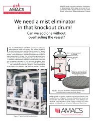
The patented <strong>AMACS</strong> <strong>Mist</strong>Fix®<br />
can solve carryover problems in<br />
vessels without a mist eliminator, as well as in vessels with a less<br />
efficient or damaged mist eliminator.<br />
In existing vessels that do not have a manway, the <strong>Mist</strong>Fix ® Insertion<br />
<strong>Mist</strong> <strong>Eliminator</strong> is an ideal choice. It is suitable for any vessel having<br />
an 8” or larger gas outlet nozzle at the top. It also eliminates the need<br />
for hazardous entry permits. Since there is no need to enter the<br />
vessel, this drastically reduces downtime, resulting in quicker<br />
turnarounds, reduced maintenance cost <strong>and</strong> production gains.<br />
<strong>Mist</strong>Fix ® also eliminates the need for modifications to vessels. For<br />
new vessels <strong>Mist</strong>Fix ® may eliminate the need for a manway <strong>and</strong><br />
reduce vessel . cost. It also makes future maintenance easier <strong>and</strong><br />
simpler.<br />
Advantages:<br />
• No Cutting of existing vessel<br />
• No Welding<br />
• No Hazardous Entry<br />
• No ASME re-certification<br />
• No Scaffolding<br />
• Minimal Downtime<br />
Figure 3. <strong>Mist</strong>Fix insertion mist eliminator<br />
<strong>AMACS</strong> <strong>Mist</strong>Fix®<br />
can easily be installed <strong>and</strong> replaced from the<br />
outside. Existing vessels require no modifications to accommodate the<br />
<strong>Mist</strong>Fix. ®<br />
For more information please call:<br />
1-800-231-0077<br />
www.amacs.com<br />
Amistco Separation Products Inc, <strong>and</strong> ACS Separations <strong>and</strong> Mass Transfer Products, are Registered Trademarks of <strong>AMACS</strong><br />
THE ENGINEERED MIST ELIMINATOR 13<br />
TEL:<br />
800-231-0077 • FAX: 713-433-6201 • WEB: www.amacs.com • EMAIL: amacs@amacs.com
Our<br />
are registered trademarks<br />
of <strong>AMACS</strong> <strong>Process</strong> <strong>Tower</strong> Internals.<br />
our<br />
Try <strong>AMACS</strong> Plate Pak vane<br />
we<br />
14
FIGURE 24<br />
APPLYING COMBINATIONS OF <strong>AMACS</strong> MESH PADS<br />
AND PLATE-PAK TM VANE UNITS TO MINIMIZE VESSEL<br />
SIZE<br />
CASE STUDIES & EXAMPLES<br />
Case Study Number 1<br />
Problem: In an HCl scrubber, an air stream of 60 acfs<br />
is coming off a bed of r<strong>and</strong>om packing <strong>and</strong> contains<br />
droplets of a weak acid. The unit operates at 122 psia<br />
at 82˚F. Determine the size of mist eliminator required<br />
to remove this mist <strong>and</strong> the removal efficiency possible.<br />
Solution: Since the acid is dilute we assume the density<br />
<strong>and</strong> viscosity of water at the operating pressure <strong>and</strong><br />
temperature:<br />
ρL = 62.4 lb/ft 3<br />
ρG = 0.60 lb/ft 3<br />
P = 122 lb/ft 2<br />
T = 82˚F<br />
F = 60 ft 3 /sec<br />
The first step is to select the mist eliminator type <strong>and</strong><br />
mesh style. As shown in Figure 24, mist coming to the<br />
mesh pad is typically comprised of droplets ranging in<br />
size from as small as 5 µm, so we select a mesh style<br />
mist eliminator to achieve this level of performance. From<br />
experience, the capacity factor for poly mesh at moderate<br />
liquid loading <strong>and</strong> lower pressures is ~.27<br />
fps. Using the Souders-Brown equation the ideal<br />
velocity is calculated:<br />
Videal = k [ (ρL- ρG) / ρG] 1/2<br />
Videal = 0.27[(62.4-0.60)/0.60] 1/2<br />
Videal = 2.74 fps<br />
The cross-sectional area of mist eliminator is determined<br />
by dividing the volumetric flow rate by the ideal<br />
velocity:<br />
Area <strong>Mist</strong> <strong>Eliminator</strong> = Volumetric Flow Rate/<br />
Superficial Vapor Velocity<br />
Area <strong>Mist</strong> <strong>Eliminator</strong> = [60 ft 3 /sec]/2.74 fps<br />
Area <strong>Mist</strong> <strong>Eliminator</strong> = 21.9 ft2<br />
The corresponding diameter is 63.4", rounded up to a<br />
st<strong>and</strong>ard 66" scrubber vessel. Note that performing<br />
the same calculations using a vane (<strong>and</strong> a capacity<br />
factor of 0.50) yields an ideal vessel diameter of 46.7",<br />
rounded up to a st<strong>and</strong>ard 48" ID vessel. To calculate<br />
the removal efficiency at 5 µm, several parameters<br />
must be identified to use equation 2 to determine the<br />
inertial parameter K:<br />
THE ENGINEERED MIST ELIMINATOR 15<br />
TEL:<br />
800-231-0077 • FAX: 713-433-6201 • WEB: www.amacs.com • EMAIL: amacs@amacs.com
K = [(ρL- ρG)Vd 2 ]/9µD<br />
K = 0.32 fps<br />
From Figure 12, the corresponding Impaction<br />
Efficiency Fraction E is ~0.08. In the Removal<br />
Efficiency Equation there is a term for the corrected<br />
specific surface area SO:<br />
SO= Specific Surface Area x 1/π x<br />
Thickness (ft) x 0.67<br />
For ACS style 8P, the specific surface area is<br />
(185 + 36) = 221 ft 2 /ft 3 , we will try both 4" <strong>and</strong> 6" thick<br />
mist eliminator thicknesses (1/3 <strong>and</strong> 1/2ft):<br />
SO = 221 x 1/3.14 x 1/3 x 0.67<br />
SO 4"thick = 15.7 <strong>and</strong> SO 6"thick = 23.6<br />
And Removal Efficiency E at 5 µm is:<br />
Efficiency = 100 – 100/e ESO<br />
Efficiency = 100 – 100/e(0.08)(15.7)<br />
Efficiency = 71.5%<br />
For the 6" thick element, the removal efficiency is<br />
84.8%. By using a composite pad containing a 2"<br />
layer of regular monofilament polypropylene, style 8P,<br />
upstream of a 2" thick layer of 8PP, mono- <strong>and</strong><br />
multi-filament co-knit, the removal efficiency is 99.9% .<br />
CASE STUDY #2<br />
Traditionally, trays are used to bring about contact<br />
between glycol <strong>and</strong> natural gas in dehydration contactors.<br />
In recent years, the industry moved towards<br />
smaller diameter columns by exploiting the higher<br />
capacities achieved with structured packing.<br />
However, the lower capital investment associated with<br />
a smaller diameter packed tower is often offset by<br />
dramatically increased glycol losses.<br />
Consider a mid-western sour gas plant operating a<br />
96" glycol contactor <strong>and</strong> processing 1,310,000 lb/hr of<br />
gas at 116˚F <strong>and</strong> 1214 psia. The gas <strong>and</strong> liquid specific<br />
densities were 4.4 <strong>and</strong> 68 lb/cu-ft respectively. The<br />
plant was experiencing 0.13 US gal of carryover per<br />
mmscf, amounting to some 65 gal/day of lost triethylene<br />
glycol, several hundred dollars worth per day. A 10"<br />
thick wire mesh mist eliminator of 12-lb mass density<br />
was installed above the packing.<br />
From experience, <strong>AMACS</strong> engineers knew that the<br />
droplet size distribution for glycol coming off the top of<br />
a packed dehydrator extends down to diameters<br />
of 5 µm <strong>and</strong> greater. Also, if the diameter of the<br />
packed column was sized in accordance with the<br />
hydraulic requirements of the packing, the wire mesh<br />
mist eliminator would be undersized.<br />
The capacity factor for 12-lb density mesh in this service<br />
is ~0.23 – 0.27, having been de-rated for the high<br />
liquid viscosity of 18 cP (which retards liquid drainage)<br />
<strong>and</strong> relatively high operating pressure. Using the gas<br />
density, volumetric flow rate <strong>and</strong> cross-sectional area<br />
of the mist eliminator, the actual superficial velocity is<br />
readily calculated. Next, using known densities of the<br />
gas <strong>and</strong> glycol, the actual or operating Capacity<br />
Factor k is determined:<br />
Vactual = kactual [(ρL- ρG) / ρG] 1/2<br />
Re-arranging for<br />
kactual = Vactual / [(ρL- ρG) / ρG] 1/2<br />
= 0.44 fps<br />
A Capacity Factor of 0.44 fps is almost twice as high<br />
as the optimum, <strong>and</strong> is in the range of that of an <strong>AMACS</strong><br />
Plate-Pak <strong>Vane</strong> mist eliminator. However, the vane<br />
will not remove particles down to 5 µm, so a meshvane<br />
assembly was proposed. The assembly has a<br />
multiple layers of mesh. The first layer is composed of<br />
highly porous mesh (<strong>AMACS</strong> style 7CA), followed by a<br />
layer of the high specific surface area (<strong>AMACS</strong> style 8DT)<br />
co-knit mesh of stainless <strong>and</strong> Dacron ® Fibers.<br />
<strong>Mist</strong>er<strong>Mesh</strong> ® drainage coils were appended to the<br />
bottom face of the mist eliminator. Downstream of the<br />
mesh was placed a Plate-Pak vane. The total<br />
thickness was 12" <strong>and</strong> was accommodated using the<br />
same supports as the mist eliminator it replaced.<br />
Carryover from a glycol contactor occurs through two<br />
mechanisms, evaporative losses <strong>and</strong> mechanical<br />
(carryover losses). In this example, simulations<br />
showed evaporative glycol losses of 0.0054<br />
gal/mmscfd. The total losses after the revamp were<br />
less than 0.008 gal/mmscfd, <strong>and</strong> carryover losses had<br />
been reduced from 0.13 gal/mmscfd, a 94% reduction!<br />
THE ENGINEERED MIST ELIMINATOR 16<br />
TEL:<br />
800-231-0077 • FAX: 713-433-6201 • WEB: www.amacs.com • EMAIL: amacs@amacs.com
THE ENGINEERED MIST ELIMINATOR 17
THE ENGINEERED MIST ELIMINATOR 18
HIGH CAPACITY MIST ELIMINATORS<br />
OUT PERFORM CONVENTIONAL TECHNOLOGY!<br />
PLATE-PAK<br />
M IST ELIMINATOR<br />
M ISTER M ESH ®<br />
MIST ELIMINATOR<br />
WITH DRAINAGE ROLLS<br />
ADVANCED TECHNOLOGY<br />
FOR DEBOTTLENECKING !<br />
Our <strong>Mist</strong>er<strong>Mesh</strong> ® <strong>Mist</strong> <strong>Eliminator</strong> out performs<br />
conventional pads. The drainage rolls<br />
accelerate liquid removal thus increasing<br />
capacity <strong>and</strong> reducing pressure drop. Used<br />
in conjunction with our Plate-Pak vane,<br />
the <strong>Mist</strong>er<strong>Mesh</strong> ® drain<br />
rolls can increase capacity<br />
by over 200% while separating<br />
droplets down to<br />
3 microns.<br />
24-hour emergency service • Free technical support • 50 years experience<br />
800-231-0077<br />
14211 Industry Street • Houston, TX 77053 • TEL: 713-434-0934 • FAX: 713-433-6201<br />
Email: amacs@amacs.com • Visit our web site www.amacs.com