Ask AMACS Solution with MistFix - AMACS Process Tower Internals
Ask AMACS Solution with MistFix - AMACS Process Tower Internals
Ask AMACS Solution with MistFix - AMACS Process Tower Internals

Create successful ePaper yourself
Turn your PDF publications into a flip-book with our unique Google optimized e-Paper software.
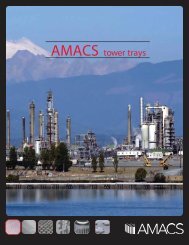
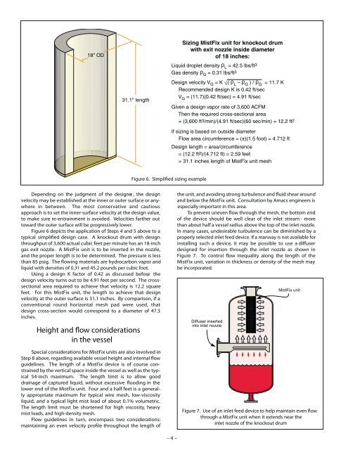
Figure 6. S sizing example<br />
Depending on the judgment of the designer , the design<br />
velocity may be established at the inner or outer surface or anywhere<br />
in between. The most conservative and cautious<br />
approach is to set the inner-surface velocity at the design value,<br />
to make sure re-entrainment is avoided. Velocities farther out<br />
toward the outer surface will be progressively lower.<br />
Figure 6 depicts the application of Steps 4 and 5 above to a<br />
typical simplified design case. A knockout drum <strong>with</strong> design<br />
throughput of 3,600 actual cubic feet per minute has an 18-inch<br />
gas exit nozzle. A <strong>MistFix</strong> unit is to be inserted in the nozzle,<br />
and the proper length is to be determined. The pressure is less<br />
than 85 psig. The owing materials are hydrocarbon vapor and<br />
liquid <strong>with</strong> densities of 0.31 and 45.2 pounds per cubic foot.<br />
Using a design K factor of 0.42 as discussed before, the<br />
design velocity turns out to be 4.91 feet per second. The crosssectional<br />
area required to achieve that velocity is 12.2 square<br />
feet. For this <strong>MistFix</strong> unit, the length to achieve that design<br />
velocity at the outer surface is 31.1 inches. By comparison, if a<br />
conventional round horizontal mesh pad were used, that<br />
design cross-section would correspond to a diameter of 47.3<br />
inches.<br />
the unit, and avoiding strong turbulence and fluid shear around<br />
and below the <strong>MistFix</strong> unit. Consultation by Amacs engineers is<br />
especially important in this area.<br />
To prevent uneven flow through the mesh, the bottom end<br />
of the device should be well clear of the inlet stream - more<br />
than about half a vessel radius above the top of the inlet nozzle.<br />
In many cases, undesirable turbulence can be diminished by a<br />
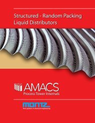
properly selected inlet feed device. If a manway is not available for<br />
installing such a device, it may be possible to use a diffuser<br />
designed for insertion through the inlet nozzle as shown in<br />
Figure 7. To control flow inequality along the length of the<br />
<strong>MistFix</strong> unit, variation in thickness or density of the mesh may<br />
be incorporated.<br />
Height and ow considerations<br />
in the vessel<br />
Special considerations for <strong>MistFix</strong> units are also involved in<br />
Step 8 above, regarding available vessel height and internal fl ow<br />
guidelines. The length of a <strong>MistFix</strong> device is of course constrained<br />
by the vertical space inside the vessel as well as the typical<br />
54-inch maximum. The length limit is to allow good<br />
drainage of captured liquid, <strong>with</strong>out excessive flooding in the<br />
lower end of the <strong>MistFix</strong> unit. Four and a half feet is a generally<br />
appropriate maximum for typical wire mesh, low-viscosity<br />
liquid, and a typical light mist load of about 0.1% volumetric.<br />
The length limit must be shortened for high viscosity, heavy<br />
mist loads, and high-density mesh.<br />
Flow guidelines in turn, encompass two considerations:<br />
maintaining an even velocity profile throughout the length of<br />
Figure 7. Use of an inlet feed device to help maintain even flow<br />
through a <strong>MistFix</strong> unit when it extends near the<br />
inlet nozzle of the knockout drum<br />
– 4 –