gy-26 manual.pdf - Elechouse
gy-26 manual.pdf - Elechouse
gy-26 manual.pdf - Elechouse

You also want an ePaper? Increase the reach of your titles
YUMPU automatically turns print PDFs into web optimized ePapers that Google loves.
www.elechouse.com<br />
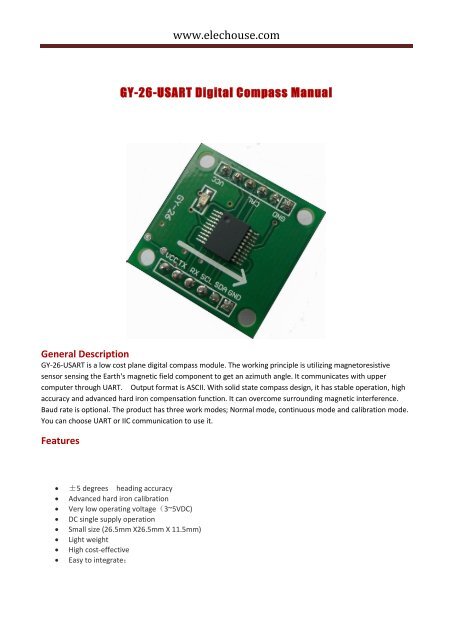
GY-<strong>26</strong>-USART Digital Compass Manual<br />
General Description<br />
GY-<strong>26</strong>-USART is a low cost plane digital compass module. The working principle is utilizing magnetoresistive<br />
sensor sensing the Earth's magnetic field component to get an azimuth angle. It communicates with upper<br />
computer through UART. Output format is ASCII. With solid state compass design, it has stable operation, high<br />
accuracy and advanced hard iron compensation function. It can overcome surrounding magnetic interference.<br />
Baud rate is optional. The product has three work modes; Normal mode, continuous mode and calibration mode.<br />
You can choose UART or IIC communication to use it.<br />
Features<br />
±5 degrees heading accuracy<br />
Advanced hard iron calibration<br />
Very low operating voltage(3~5VDC)<br />
DC single supply operation<br />
Small size (<strong>26</strong>.5mm X<strong>26</strong>.5mm X 11.5mm)<br />
Light weight<br />
High cost-effective<br />
Easy to integrate;
www.elechouse.com<br />
Applications<br />
1. Hand-held electronic instruments.<br />
2. Robot orientation and position.<br />
3. Navigation system.<br />
4. Telescope position.<br />
5. Autohelm rudder.<br />
6. Antenna position.<br />
7. Automobile GPS navigation.<br />
8. Aero model position.<br />
Basic parameters<br />
1. Directions (In level condition)<br />
Accuracy:
www.elechouse.com<br />
Pin Configuration<br />
Pin number Pin name Description<br />
1 VCC Power Supply Input<br />
2 TXD Transmit Data Output<br />
3 RXD Receive Data Input<br />
4 SCL IIC SCL<br />
5 SDA IIC SDA<br />
6 GND Ground<br />
7 GND Ground<br />
8 GND Ground<br />
9 CAL Calibrate<br />
10 NC No Connection<br />
11 NC No Connection<br />
12 VCC Power Supply Input
www.elechouse.com<br />
Technical terms<br />
1. Declination Angle<br />
It is the angle between magnetic north and true north. Declination angles of different place are<br />
different, even at the same place declination angles varies with the time. When we use compass to<br />
navigation, we get directions relative to magnetic north. So we can get directions relative to true<br />
north through declination angle compensation. For example, the current direction counted by<br />
compass is north by east 30 degrees and the declination angle is 5 degrees. So the direction relative<br />
to true north is 35 degrees (30+5°=35°).<br />
2. Installation Angle<br />
There is an arrowhead on the compass module and it’s used to denote directions. When installed, it<br />
requests that forward direction of the object surveyed is consistent with the arrowhead. So the<br />
direction counted by the compass is the right direction. If installing direction is not consistent with the<br />
arrowhead, there is an included angle and it is the deviation angle. Only after we compensate it, the<br />
compass outputs the true direction.<br />
3. Calibration<br />
It’s also called hard iron compensation. All digital compasses must be calibrated before been used.<br />
Once hard iron conditions changed, the magnetic field conditions will be changed too. At this time,<br />
angle information counted by the compass will be inaccurate. In order to remove the influence, it’s<br />
necessary to calibrate the compass.<br />
4. Calibrating methods and functions<br />
When magnetic field changes angle information counted by compass will be inaccurate. This time it is<br />
necessary to calibrate the compass to remove the influence.<br />
Methods:<br />
Send “0xC0” command, and then rotate the compass two circles slowly, equably and flatly, fast not<br />
allowed. One cycle needs more than one minute. Then send “0xC1” command to finish calibration.<br />
Use serial communication<br />
1. Parameters<br />
Baud rate: 9600bps<br />
Verify bit: N
www.elechouse.com<br />
Data bits: 8<br />
Stop bit: 1<br />
2. Output format of the module,8 bytes included in each frame<br />
(1)Byte0:0x0D<br />
(2)Byte1:0x0A<br />
(ASCII: enter)<br />
(ASCII: new line)<br />
(3)Byte2:0x30~0x33 (ASCII: hundreds of angle 0~3)<br />
(4)Byte3:0x30~0x39 (ASCII: tens of angle 0~3)<br />
(5)Byte4:0x30~0x39 (ASCII: bits of angle 0~3)<br />
(6)Byte5:0x2E<br />
(7)Byte6: 0x30~0x39<br />
(8)Byte7: 0x00~0xFF<br />
(ASCII: decimal point of angle)<br />
(ASCII: decimal of angle)<br />
(calibrate sum)<br />
Byte7= the lower 8 bits of (Byte0+ Byte1+ Byte2+……Byte6)<br />
Example: = 359.6°<br />
3 Commands been sent to the module<br />
(1)0x31: measure the angle (return the value of the angle)<br />
(2)0xC0: start calibration<br />
(3)0xC1: end calibration<br />
(4) 0xA0-0xAA-0xA5-0xC5: return to the settings of the factory<br />
(5) 0xA0-0xAA-0xA5-IIC_ADDR: change the IIC bus address<br />
(6)0x03-DECL_high: set the high 8 bits of declination angle<br />
(7)0x04-DECL_low: set the low 8 bits of declination angle<br />
Example1: send 0xC0 to the module, it return<br />
, which means starting calibration successfully.<br />
Example2: send 0x03,0x00,0x04,0x64 to the module, it return<br />
which means the declination angle been<br />
changed to 10.0 degrees successfully.
www.elechouse.com<br />
Use IIC<br />
1 Address<br />
When using the IIC communication, the module is similar to a 24C04,EEPROM. The communication is<br />
very simple. The addresses of the data in the module are shown in the following table.<br />
address in the<br />
module<br />
0x00<br />
0x01<br />
0x02<br />
0x03<br />
0x04<br />
0x05<br />
0x06<br />
0x07<br />
its meanings<br />
not been used<br />
high 8 bits of the<br />
angle<br />
low 8 bits of the<br />
angle<br />
high 8 bits of the<br />
declination angle<br />
low 8 bits of the<br />
declination angle<br />
not been used<br />
not been used<br />
Level value<br />
calibration<br />
2 Commands(been sent to the module through IIC)<br />
command<br />
function<br />
0x00+ 0x31 angle measure<br />
0x00+ 0xC0 Start calibration<br />
0x00+ 0xC1 End calibration
www.elechouse.com<br />
0x00+(0xA0+0xAA+0xA5+0xC5)<br />
0x00+(0xA0+0xAA+0xA5+IIC_ADDR)<br />
Return to the<br />
factory settings<br />
Change the IIC<br />
address<br />
0x03 + DECL_HIGH Change the high 8<br />
bits of declination<br />
angle<br />
0x04 + DECL_LOW Change the low 8<br />
bits of declination<br />
angle<br />
3 Change the IIC address<br />
The IIC address of the module can be changed. The default factory address of the module is<br />
0xE0.When powering the module, the Led blinks according to its address.<br />
address<br />
Blinking times<br />
0xe0 0<br />
0xe2 1<br />
0xe4 2<br />
0xe6 3<br />
0xe8 4<br />
0xea 5<br />
0xec 6<br />
0xee 7<br />
0xf0 8<br />
0xf2 9<br />
0xf4 10
www.elechouse.com<br />
0xf6 11<br />
0xf8 12<br />
0xfa 13<br />
0xfc 14<br />
0xfe 15<br />
Command:<br />
Send 0x31:(get angle)<br />
Byte0 Byte1 Byte2 Byte3 Byte4 Byte5 Byte6 Byte7<br />
0x0D 0x0A 0x30~0x33 0x30~0x39 0x30~0x39 0x2E 0x30~0x39 0x00~0xFF<br />
Send 0x35:(get temperature)<br />
Byte0 Byte1 Byte2 Byte3 Byte4 Byte5 Byte6 Byte7<br />
0x0D 0x0A 0x30~0x33 0x30~0x39 0x30~0x39 0x2E 0x30~0x39 0x00~0xFF<br />
Send 0xC0:(Calibration)<br />
Byte0 Byte1 Byte2 Byte3 Byte4 Byte5 Byte6 Byte7<br />
0x0D 0x0A 0x30 0x30 0x30 0x2E 0x30 0x05<br />
Send 0xC1:(finish Calibration)<br />
Byte0 Byte1 Byte2 Byte3 Byte4 Byte5 Byte6 Byte7<br />
0x0D 0x0A 0x30~0x33 0x30~0x39 0x30~0x39 0x2E 0x30~0x39 0x00~0xFF<br />
Send 0xA0+0xAA+0xA5+0xC5:(Restoring Factory Calibration)<br />
Byte0 Byte1 Byte2 Byte3 Byte4 Byte5 Byte6 Byte7
www.elechouse.com<br />
0x0D 0x0A 0x30 0x30 0x30 0x2E 0x30 0x05<br />
Send 0x03+:Compass bearing high 8bit<br />
Byte0 Byte1 Byte2 Byte3 Byte4 Byte5 Byte6 Byte7<br />
0x0D 0x0A 0x30 0x30 0x30 0x2E 0x30 0x05<br />
Send 0x04+:Compass bearing low 8bit<br />
Byte0 Byte1 Byte2 Byte3 Byte4 Byte5 Byte6 Byte7<br />
0x0D 0x0A 0x30 0x30 0x30 0x2E 0x30 0x05<br />
Remarks<br />
1. All the parameters of the module are tested with the standard 5V power supply, so we advise you to use the<br />
power with small ripples.<br />
2. When using the module, please keep it level so that it can get the accurate results.<br />
3. The module can be connected with SCM or some other device with the right interface, but it can not be<br />
connected to the serial port of the computer directly. However, you can use a USB to serial module to<br />
connect it to the computer.