Section 17 Strength and Durability of Gears - SDP/SI
Section 17 Strength and Durability of Gears - SDP/SI
Section 17 Strength and Durability of Gears - SDP/SI

Create successful ePaper yourself
Turn your PDF publications into a flip-book with our unique Google optimized e-Paper software.
ELEMENTS OF METRIC GEAR TECHNOLOGY<br />
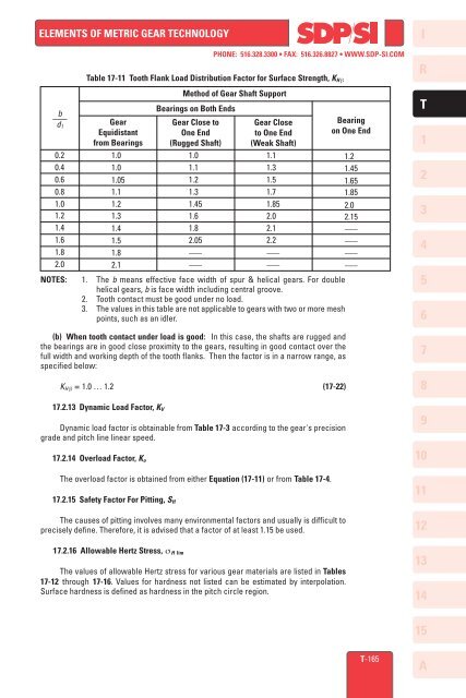
b<br />
–––<br />
d 1<br />
0.2<br />
0.4<br />
0.6<br />
0.8<br />
1.0<br />
1.2<br />
1.4<br />
1.6<br />
1.8<br />
2.0<br />
PHONE: 516.328.3300 • FAX: 516.326.8827 • WWW.<strong>SDP</strong>-<strong>SI</strong>.COM<br />
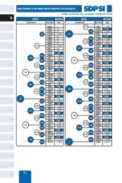
Table <strong>17</strong>-11 Tooth Flank Load Distribution Factor for Surface <strong>Strength</strong>, K H β<br />
Gear<br />
Equidistant<br />
from Bearings<br />
1.0<br />
1.0<br />
1.05<br />
1.1<br />
1.2<br />
1.3<br />
1.4<br />
1.5<br />
1.8<br />
2.1<br />
Method <strong>of</strong> Gear Shaft Support<br />
Bearings on Both Ends<br />
Gear Close to<br />
One End<br />
(Rugged Shaft)<br />
1.0<br />
1.1<br />
1.2<br />
1.3<br />
1.45<br />
1.6<br />
1.8<br />
2.05<br />
–––<br />
–––<br />
Gear Close<br />
to One End<br />
(Weak Shaft)<br />
1.1<br />
1.3<br />
1.5<br />
1.7<br />
1.85<br />
2.0<br />
2.1<br />
2.2<br />
–––<br />
–––<br />
NOTES: 1. The b means effective face width <strong>of</strong> spur & helical gears. For double<br />
helical gears, b is face width including central groove.<br />
2. Tooth contact must be good under no load.<br />
3. The values in this table are not applicable to gears with two or more mesh<br />
points, such as an idler.<br />
(b) When tooth contact under load is good: In this case, the shafts are rugged <strong>and</strong><br />
the bearings are in good close proximity to the gears, resulting in good contact over the<br />
full width <strong>and</strong> working depth <strong>of</strong> the tooth flanks. Then the factor is in a narrow range, as<br />
specified below:<br />
K H β = 1.0 … 1.2 (<strong>17</strong>-22)<br />
<strong>17</strong>.2.13 Dynamic Load Factor, K V<br />
Dynamic load factor is obtainable from Table <strong>17</strong>-3 according to the gear's precision<br />
grade <strong>and</strong> pitch line linear speed.<br />
<strong>17</strong>.2.14 Overload Factor, K o<br />
The overload factor is obtained from either Equation (<strong>17</strong>-11) or from Table <strong>17</strong>-4.<br />
<strong>17</strong>.2.15 Safety Factor For Pitting, S H<br />
The causes <strong>of</strong> pitting involves many environmental factors <strong>and</strong> usually is difficult to<br />
precisely define. Therefore, it is advised that a factor <strong>of</strong> at least 1.15 be used.<br />
Bearing<br />
on One End<br />
1.2<br />
1.45<br />
1.65<br />
1.85<br />
2.0<br />
2.15<br />
–––<br />
–––<br />
–––<br />
–––<br />
I<br />
R<br />
T<br />
1<br />
2<br />
3<br />
4<br />
5<br />
6<br />
7<br />
8<br />
9<br />
10<br />
11<br />
12<br />
<strong>17</strong>.2.16 Allowable Hertz Stress, σ H lim<br />
The values <strong>of</strong> allowable Hertz stress for various gear materials are listed in Tables<br />
<strong>17</strong>-12 through <strong>17</strong>-16. Values for hardness not listed can be estimated by interpolation.<br />
Surface hardness is defined as hardness in the pitch circle region.<br />
13<br />
14<br />
15<br />
T-165<br />
A