Section 17 Strength and Durability of Gears - SDP/SI
Section 17 Strength and Durability of Gears - SDP/SI
Section 17 Strength and Durability of Gears - SDP/SI

You also want an ePaper? Increase the reach of your titles
YUMPU automatically turns print PDFs into web optimized ePapers that Google loves.
ELEMENTS OF METRIC GEAR TECHNOLOGY<br />
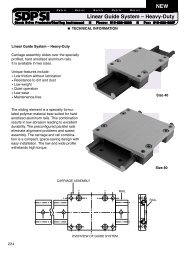
Nitriding<br />
Steel<br />
Module 1.5<br />
A 0.2<br />
Depth, mm<br />
B 0.3<br />
2<br />
0.2<br />
0.3<br />
PHONE: 516.328.3300 • FAX: 516.326.8827 • WWW.<strong>SDP</strong>-<strong>SI</strong>.COM<br />
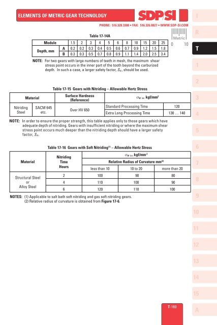
Table <strong>17</strong>-14A<br />
3<br />
0.3<br />
0.5<br />
4<br />
0.4<br />
0.7<br />
5<br />
0.5<br />
0.8<br />
6<br />
0.6<br />
0.9<br />
8<br />
0.7<br />
1.1<br />
10<br />
0.9<br />
1.4<br />
15<br />
1.2<br />
2.0<br />
NOTE: For two gears with large numbers <strong>of</strong> teeth in mesh, the maximum shear<br />
stress point occurs in the inner part <strong>of</strong> the tooth beyond the carburized<br />
depth. In such a case, a larger safety factor, S H , should be used.<br />
Table <strong>17</strong>-15 <strong>Gears</strong> with Nitriding – Allowable Hertz Stress<br />
Surface Hardness<br />
Material σ H lim kgf/mm 2<br />
(Reference)<br />
NOTE: In order to ensure the proper strength, this table applies only to those gears which have<br />
adequate depth <strong>of</strong> nitriding. <strong>Gears</strong> with insufficient nitriding or where the maximum shear<br />
stress point occurs much deeper than the nitriding depth should have a larger safety<br />
factor, S H .<br />
Material<br />
Structural Steel<br />
or<br />
Alloy Steel<br />
SACM 645<br />
etc.<br />
Over HV 650<br />
St<strong>and</strong>ard Processing Time<br />
Extra Long Processing Time<br />
Table <strong>17</strong>-16 <strong>Gears</strong> with S<strong>of</strong>t Nitriding (1) – Allowable Hertz Stress<br />
Nitriding<br />
Time<br />
Hours<br />
2<br />
4<br />
6<br />
less than 10<br />
NOTES: (1) Applicable to salt bath s<strong>of</strong>t nitriding <strong>and</strong> gas s<strong>of</strong>t nitriding gears.<br />
(2) Relative radius <strong>of</strong> curvature is obtained from Figure <strong>17</strong>-6.<br />
100<br />
110<br />
120<br />
σ H lim kgf/mm 2<br />
20<br />
1.5<br />
2.5<br />
25<br />
1.8<br />
3.4<br />
Relative Radius <strong>of</strong> Curvature mm (2)<br />
10 to 20<br />
90<br />
100<br />
110<br />
Metric<br />
0 10<br />
120<br />
130 … 140<br />
more than 20<br />
80<br />
90<br />
100<br />
I<br />
R<br />
T<br />
1<br />
2<br />
3<br />
4<br />
5<br />
6<br />
7<br />
8<br />
9<br />
10<br />
11<br />
12<br />
13<br />
14<br />
15<br />
T-169<br />
A