Section 17 Strength and Durability of Gears - SDP/SI
Section 17 Strength and Durability of Gears - SDP/SI
Section 17 Strength and Durability of Gears - SDP/SI

You also want an ePaper? Increase the reach of your titles
YUMPU automatically turns print PDFs into web optimized ePapers that Google loves.
ELEMENTS OF METRIC GEAR TECHNOLOGY<br />
PHONE: 516.328.3300 • FAX: 516.326.8827 • WWW.<strong>SDP</strong>-<strong>SI</strong>.COM<br />
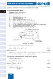
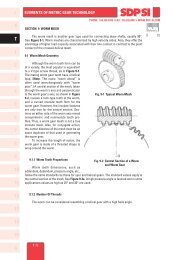
It should be noted that the greatest bending stress is at the root <strong>of</strong> the flank or base<br />
<strong>of</strong> the dedendum. Thus, it can be stated:<br />
σ F = actual stress on dedendum at root<br />
σ F lim = allowable stress<br />
Then Equation (<strong>17</strong>-4) becomes Equation (<strong>17</strong>-5)<br />
σ F ≤ σ F lim (<strong>17</strong>-5)<br />
Equation (<strong>17</strong>-6) presents the calculation <strong>of</strong> F t lim :<br />
m n b K L K FX 1<br />
F t lim = σ F lim ––––––– (––––––) ––– (kgf) (<strong>17</strong>-6)<br />
Y F Y ε Y β K V K O S F<br />
Equation (<strong>17</strong>-6) can be converted into stress by Equation (<strong>17</strong>-7):<br />
Y F Y ε Y β K V K<br />
σ O<br />
F = F t –––––– (–––––) S F (kgf/mm 2 ) (<strong>17</strong>-7)<br />
m n b K L K FX<br />
<strong>17</strong>.1.1 Determination <strong>of</strong> Factors in the Bending <strong>Strength</strong> Equation<br />
If the gears in a pair have different blank widths, let the wider one be b w <strong>and</strong> the<br />
narrower one be b s .<br />
And if:<br />
b w – b s ≤ m n , b w <strong>and</strong> b s can be put directly into Equation (<strong>17</strong>-6).<br />
b w – b s > m n , the wider one would be changed to b s + m n <strong>and</strong> the narrower one,<br />
b s , would be unchanged.<br />
<strong>17</strong>.1.2 Tooth Pr<strong>of</strong>ile Factor, Y F<br />
The factor Y F is obtainable from Figure <strong>17</strong>-1 based on the equivalent number <strong>of</strong> teeth,<br />
z v , <strong>and</strong> coefficient <strong>of</strong> pr<strong>of</strong>ile shift, x, if the gear has a st<strong>and</strong>ard tooth pr<strong>of</strong>ile with 20° pressure<br />
angle, per JIS B <strong>17</strong>01. The theoretical limit <strong>of</strong> undercut is shown. Also, for pr<strong>of</strong>ile shifted<br />
gears the limit <strong>of</strong> too narrow (sharp) a tooth top l<strong>and</strong> is given. For internal gears, obtain the<br />
factor by considering the equivalent racks.<br />
<strong>17</strong>.1.3 Load Distribution Factor, Yε<br />
Load distribution factor is the reciprocal <strong>of</strong> radial contact ratio.<br />
1<br />
Yε = ––– (<strong>17</strong>-8)<br />
ε α<br />
Table <strong>17</strong>-1 shows the radial contact ratio <strong>of</strong> a st<strong>and</strong>ard spur gear.<br />
Metric<br />
0 10<br />
I<br />
R<br />
T<br />
1<br />
2<br />
3<br />
4<br />
5<br />
6<br />
7<br />
8<br />
9<br />
10<br />
11<br />
12<br />
13<br />
14<br />
15<br />
T-151<br />
A