Section 17 Strength and Durability of Gears - SDP/SI
Section 17 Strength and Durability of Gears - SDP/SI
Section 17 Strength and Durability of Gears - SDP/SI

You also want an ePaper? Increase the reach of your titles
YUMPU automatically turns print PDFs into web optimized ePapers that Google loves.
ELEMENTS OF METRIC GEAR TECHNOLOGY<br />
Correction Factor C<br />
1.6<br />
1.5<br />
1.4<br />
1.3<br />
1.2<br />
1.1<br />
1.0<br />
0.9<br />
0.8<br />
0.7<br />
0.6<br />
0.5<br />
– 0.3 – 0.2 – 0.1 0 0.1 0.2 0.3<br />
Axial Shift Factor, K<br />
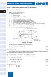
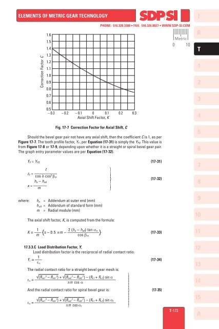
Fig. <strong>17</strong>-7 Correction Factor for Axial Shift, C<br />
PHONE: 516.328.3300 • FAX: 516.326.8827 • WWW.<strong>SDP</strong>-<strong>SI</strong>.COM<br />
Should the bevel gear pair not have any axial shift, then the coefficient C is 1, as per<br />
Figure <strong>17</strong>-7. The tooth pr<strong>of</strong>ile factor, Y F , per Equation (<strong>17</strong>-31) is simply the Y FO . This value is<br />
from Figure <strong>17</strong>-8 or <strong>17</strong>-9, depending upon whether it is a straight or spiral bevel gear pair.<br />
The graph entry parameter values are per Equation (<strong>17</strong>-32).<br />
Y F = Y FO (<strong>17</strong>-31)<br />
z<br />
⎫<br />
z v = ––––––––––<br />
cos δ cos 3 β m ⎪ ⎬ (<strong>17</strong>-32)<br />
h a – h a0<br />
⎪<br />
x = ––––––<br />
m<br />
⎪<br />
⎭<br />
where: h a = Addendum at outer end (mm)<br />
h a0 = Addendum <strong>of</strong> st<strong>and</strong>ard form (mm)<br />
m = Radial module (mm)<br />
The axial shift factor, K, is computed from the formula:<br />
1 2 (h a – h a0 ) tan α<br />
K = ––– n<br />
{s – 0.5 πm – ––––––––––––––} (<strong>17</strong>-33)<br />
m<br />
cos β m<br />
Metric<br />
0 10<br />
I<br />
R<br />
T<br />
1<br />
2<br />
3<br />
4<br />
5<br />
6<br />
7<br />
8<br />
9<br />
10<br />
11<br />
<strong>17</strong>.3.3.C Load Distribution Factor, Y ε<br />
Load distribution factor is the reciprocal <strong>of</strong> radial contact ratio.<br />
1<br />
Y ε = ––– (<strong>17</strong>-34)<br />
ε α<br />
The radial contact ratio for a straight bevel gear mesh is:<br />
⎫<br />
2<br />
√(R va1 – R 2 2 2 vb1 ) + √(R va2 – R vb2 ) – (R v1 + R v2 ) sin α<br />
ε α = ––––––––––––––––––––––––––––––––––––––––<br />
πm cos α<br />
⎪ ⎪⎪<br />
And the radial contact ratio for spiral bevel gear is: ⎬ (<strong>17</strong>-35)<br />
2<br />
√(R va1 – R 2 2 2 vb1 ) + √(R va2 – R vb2 ) – (R v1 + R v2 ) sin α t<br />
ε α = –––––––––––––––––––––––––––––––––––––––– ⎪<br />
πm cos α t<br />
⎭<br />
T-<strong>17</strong>3<br />
12<br />
13<br />
14<br />
15<br />
A