Section 17 Strength and Durability of Gears - SDP/SI
Section 17 Strength and Durability of Gears - SDP/SI
Section 17 Strength and Durability of Gears - SDP/SI

Create successful ePaper yourself
Turn your PDF publications into a flip-book with our unique Google optimized e-Paper software.
I<br />
R<br />
T<br />
1<br />
2<br />
3<br />
4<br />
5<br />
6<br />
7<br />
8<br />
9<br />
10<br />
11<br />
12<br />
13<br />
14<br />
ELEMENTS OF METRIC GEAR TECHNOLOGY<br />
SECTION <strong>17</strong> STRENGTH AND DURABILITY OF GEARS<br />
PHONE: 516.328.3300 • FAX: 516.326.8827 • WWW.<strong>SDP</strong>-<strong>SI</strong>.COM<br />
The strength <strong>of</strong> gears is generally expressed in terms <strong>of</strong> bending strength <strong>and</strong> surface<br />
durability. These are independent criteria which can have differing criticalness, although<br />
usually both are important.<br />
Discussions in this section are based upon equations published in the literature <strong>of</strong><br />
the Japanese Gear Manufacturer Association (JGMA). Reference is made to the following<br />
JGMA specifications:<br />
Specifications <strong>of</strong> JGMA:<br />
JGMA 401-01<br />
JGMA 402-01<br />
JGMA 403-01<br />
JGMA 404-01<br />
JGMA 405-01<br />
Bending <strong>Strength</strong> Formula <strong>of</strong> Spur <strong>Gears</strong> <strong>and</strong> Helical <strong>Gears</strong><br />
Surface <strong>Durability</strong> Formula <strong>of</strong> Spur <strong>Gears</strong> <strong>and</strong> Helical <strong>Gears</strong><br />
Bending <strong>Strength</strong> Formula <strong>of</strong> Bevel <strong>Gears</strong><br />
Surface <strong>Durability</strong> Formula <strong>of</strong> Bevel <strong>Gears</strong><br />
The <strong>Strength</strong> Formula <strong>of</strong> Worm <strong>Gears</strong><br />
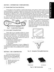
Generally, bending strength <strong>and</strong> durability specifications are applied to spur <strong>and</strong><br />
helical gears (including double helical <strong>and</strong> internal gears) used in industrial machines in<br />
the following range:<br />
Module: m 1.5 to 25 mm<br />
Pitch Diameter: d 25 to 3200 mm<br />
Tangential Speed: v less than 25 m/sec<br />
Rotating Speed: n less than 3600 rpm<br />
Conversion Formulas: Power, Torque <strong>and</strong> Force<br />
Gear strength <strong>and</strong> durability relate to the power <strong>and</strong> forces to be transmitted. Thus, the<br />
equations that relate tangential force at the pitch circle, F t (kgf), power, P (kw), <strong>and</strong> torque,<br />
T (kgf • m) are basic to the calculations. The relations are as follows:<br />
102 P 1.95 x 10 6 P 2000 T<br />
F t = –––– = –––––––––– = ––––– (<strong>17</strong>-1)<br />
v d w n d w<br />
F t v 10 –6<br />
P = –––– = –––– F t d wn (<strong>17</strong>-2)<br />
102 1.95<br />
F t d w 974 P<br />
T = –––– = ––––– (<strong>17</strong>-3)<br />
2000 n<br />
where: v : Tangential Speed <strong>of</strong> Working Pitch Circle (m/sec)<br />
d w n<br />
v = –––––<br />
19100<br />
d w<br />
n<br />
: Working Pitch Diameter (mm)<br />
: Rotating Speed (rpm)<br />
<strong>17</strong>.1 Bending <strong>Strength</strong> Of Spur And Helical <strong>Gears</strong><br />
In order to confirm an acceptable safe bending strength, it is necessary to analyze<br />
the applied tangential force at the working pitch circle, F t , vs. allowable force, F t lim. This is<br />
stated as:<br />
F t ≤ F t lim (<strong>17</strong>-4)<br />
Metric<br />
0 10<br />
15<br />
A<br />
T-150
ELEMENTS OF METRIC GEAR TECHNOLOGY<br />
PHONE: 516.328.3300 • FAX: 516.326.8827 • WWW.<strong>SDP</strong>-<strong>SI</strong>.COM<br />
It should be noted that the greatest bending stress is at the root <strong>of</strong> the flank or base<br />
<strong>of</strong> the dedendum. Thus, it can be stated:<br />
σ F = actual stress on dedendum at root<br />
σ F lim = allowable stress<br />
Then Equation (<strong>17</strong>-4) becomes Equation (<strong>17</strong>-5)<br />
σ F ≤ σ F lim (<strong>17</strong>-5)<br />
Equation (<strong>17</strong>-6) presents the calculation <strong>of</strong> F t lim :<br />
m n b K L K FX 1<br />
F t lim = σ F lim ––––––– (––––––) ––– (kgf) (<strong>17</strong>-6)<br />
Y F Y ε Y β K V K O S F<br />
Equation (<strong>17</strong>-6) can be converted into stress by Equation (<strong>17</strong>-7):<br />
Y F Y ε Y β K V K<br />
σ O<br />
F = F t –––––– (–––––) S F (kgf/mm 2 ) (<strong>17</strong>-7)<br />
m n b K L K FX<br />
<strong>17</strong>.1.1 Determination <strong>of</strong> Factors in the Bending <strong>Strength</strong> Equation<br />
If the gears in a pair have different blank widths, let the wider one be b w <strong>and</strong> the<br />
narrower one be b s .<br />
And if:<br />
b w – b s ≤ m n , b w <strong>and</strong> b s can be put directly into Equation (<strong>17</strong>-6).<br />
b w – b s > m n , the wider one would be changed to b s + m n <strong>and</strong> the narrower one,<br />
b s , would be unchanged.<br />
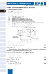
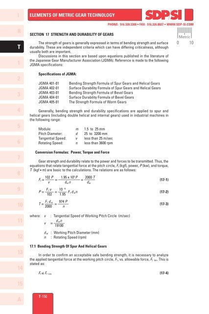
<strong>17</strong>.1.2 Tooth Pr<strong>of</strong>ile Factor, Y F<br />
The factor Y F is obtainable from Figure <strong>17</strong>-1 based on the equivalent number <strong>of</strong> teeth,<br />
z v , <strong>and</strong> coefficient <strong>of</strong> pr<strong>of</strong>ile shift, x, if the gear has a st<strong>and</strong>ard tooth pr<strong>of</strong>ile with 20° pressure<br />
angle, per JIS B <strong>17</strong>01. The theoretical limit <strong>of</strong> undercut is shown. Also, for pr<strong>of</strong>ile shifted<br />
gears the limit <strong>of</strong> too narrow (sharp) a tooth top l<strong>and</strong> is given. For internal gears, obtain the<br />
factor by considering the equivalent racks.<br />
<strong>17</strong>.1.3 Load Distribution Factor, Yε<br />
Load distribution factor is the reciprocal <strong>of</strong> radial contact ratio.<br />
1<br />
Yε = ––– (<strong>17</strong>-8)<br />
ε α<br />
Table <strong>17</strong>-1 shows the radial contact ratio <strong>of</strong> a st<strong>and</strong>ard spur gear.<br />
Metric<br />
0 10<br />
I<br />
R<br />
T<br />
1<br />
2<br />
3<br />
4<br />
5<br />
6<br />
7<br />
8<br />
9<br />
10<br />
11<br />
12<br />
13<br />
14<br />
15<br />
T-151<br />
A
I<br />
ELEMENTS OF METRIC GEAR TECHNOLOGY<br />
R<br />
T<br />
1<br />
2<br />
3<br />
3.8<br />
3.7<br />
3.6<br />
3.5<br />
3.4<br />
3.3<br />
PHONE: 516.328.3300 • FAX: 516.326.8827 • WWW.<strong>SDP</strong>-<strong>SI</strong>.COM<br />
Normal STD Pressure<br />
Angle α n = 20°<br />
Addendum h a = 1.00 m n<br />
Dedendum h f = 1.25 m n<br />
Corner Radius <strong>of</strong> Cutter<br />
γ = 0.375 m n<br />
Metric<br />
0 10<br />
3.5<br />
3.4<br />
3.3<br />
4<br />
3.2<br />
3.2<br />
5<br />
6<br />
7<br />
8<br />
Tooth Pr<strong>of</strong>ile Factor, YF (Form Factor)<br />
3.1<br />
3.0<br />
2.9<br />
2.8<br />
2.7<br />
2.6<br />
2.5<br />
Theoretical Undercut Limit<br />
X = 0.1<br />
X = –0.2<br />
X = –0.1<br />
X = 0<br />
X = –0.3<br />
X = –0.4<br />
X = –0.5<br />
3.1<br />
3.0<br />
2.9<br />
2.8<br />
2.7<br />
2.6<br />
2.5<br />
9<br />
10<br />
11<br />
12<br />
13<br />
14<br />
2.4<br />
2.3<br />
2.2<br />
2.1<br />
2.0<br />
1.9<br />
Narrow Tooth Top Limit<br />
X = 0.7<br />
X = 0.8<br />
X = 0.9<br />
X = 1.0<br />
X = 0.6<br />
X = 0.2<br />
X = 0.4<br />
X = 0.3<br />
X = 0.5<br />
1.8<br />
1.8<br />
10 11 12 13 14 15 16 <strong>17</strong> 18 19 20 25 30 35 40 45 50 60 80 100 200 400 ∞<br />
z<br />
Equivalent Spur Gear Number <strong>of</strong> Teeth z v = –––––<br />
cos 3 β<br />
Fig. <strong>17</strong>-1 Chart <strong>of</strong> Tooth Pr<strong>of</strong>ile Factor, Y F<br />
2.4<br />
2.3<br />
2.2<br />
2.1<br />
2.0<br />
1.9<br />
15<br />
A<br />
T-152
ELEMENTS OF METRIC GEAR TECHNOLOGY<br />
PHONE: 516.328.3300 • FAX: 516.326.8827 • WWW.<strong>SDP</strong>-<strong>SI</strong>.COM<br />
Metric<br />
0 10<br />
I<br />
R<br />
T<br />
110 120<br />
1.863<br />
1.867 1.871<br />
1.992 1.926<br />
1<br />
95 100<br />
1.847<br />
1.850 1.853<br />
1.855 1.858<br />
1.859 1.862<br />
1.914 1.9<strong>17</strong><br />
2<br />
Table <strong>17</strong>-1 Radial Contact Ratio <strong>of</strong> St<strong>and</strong>ard Spur <strong>Gears</strong>, εα (α = 20°)<br />
25 30 35 40 45 50 55 60 65 70 75 80 85 90<br />
1.612<br />
1.654<br />
1.633<br />
1.687<br />
1.670<br />
1.649<br />
1.663 1.684 1.700 1.714<br />
1.674 1.695 1.711 1.725 1.736<br />
1.683 1.704 1.721 1.734 1.745 1.755<br />
1.691 1.712 1.729 1.742 1.753 1.763 1.771<br />
1.698 1.719 1.736 1.749 1.760 1.770 1.778 1.785<br />
1.704 1.725 1.742 1.755 1.766 1.776 1.784 1.791 1.797<br />
1.710 1.731 1.747 1.761 1.772 1.781 1.789 1.796 1.802 1.808<br />
1.714 1.735 1.752 1.765 1.777 1.786 1.794 1.801 1.807 1.812 1.8<strong>17</strong><br />
1.719 1.740 1.756 1.770 1.781 1.790 1.798 1.805 1.811 1.8<strong>17</strong> 1.821 1.826<br />
1.723 1.743 1.760 1.773 1.785 1.794 1.802 1.809 1.815 1.821 1.825 1.830 1.833<br />
1.726 1.747 1.764 1.777 1.788 1.798 1.806 1.813 1.819 1.824 1.829 1.833 1.837 1.840<br />
1.729 1.750 1.767 1.780 1.791 1.801 1.809 1.816 1.822 1.827 1.832 1.836 1.840 1.844<br />
1.732 1.753 1.770 1.783 1.794 1.804 1.812 1.819 1.825 1.830 1.835 1.839 1.843 1.846<br />
1.737 1.758 1.775 1.788 1.799 1.809 1.8<strong>17</strong> 1.824 1.830 1.835 1.840 1.844 1.848 1.852<br />
1.742 1.762 1.779 1.792 1.804 1.813 1.821 1.828 1.834 1.840 1.844 1.849 1.852 1.856<br />
1.797 1.8<strong>17</strong> 1.834 1.847 1.859 1.868 1.876 1.883 1.889 1.894 1.899 1.903 1.907 1.911<br />
3<br />
4<br />
5<br />
6<br />
7<br />
8<br />
9<br />
10<br />
20<br />
15<br />
1.481<br />
1.519 1.557<br />
1.547 1.584<br />
1.567 1.605<br />
1.584 1.622<br />
1.597 1.635<br />
1.609 1.646<br />
1.618 1.656<br />
1.626 1.664<br />
1.633 1.671<br />
1.639 1.677<br />
1.645 1.682<br />
1.649 1.687<br />
1.654 1.691<br />
1.657 1.695<br />
1.661 1.699<br />
1.664 1.702<br />
1.667 1.705<br />
1.672 1.710<br />
1.676 1.714<br />
1.731 1.769<br />
11<br />
12<br />
1.420<br />
12<br />
1.451<br />
15<br />
20 1.489<br />
25 1.516<br />
30 1.537<br />
35 1.553<br />
40 1.567<br />
45 1.578<br />
50 1.588<br />
55 1.596<br />
60 1.603<br />
65 1.609<br />
70 1.614<br />
75 1.619<br />
80 1.623<br />
85 1.627<br />
90 1.630<br />
95 1.634<br />
100 1.636<br />
110 1.642<br />
120 1.646<br />
RACK 1.701<br />
12<br />
<strong>17</strong>.1.4 Helix Angle Factor, Y β<br />
Helix angle factor can be obtained from Equation (<strong>17</strong>-9).<br />
β<br />
When 0 ≤ β ≤ 30°, then Y β = 1 – –––<br />
⎫<br />
120 ⎪ ⎬ (<strong>17</strong>-9)<br />
⎪<br />
When β > 30°, then Y β = 0.75<br />
⎭<br />
13<br />
14<br />
15<br />
T-153<br />
A
I<br />
R<br />
T<br />
ELEMENTS OF METRIC GEAR TECHNOLOGY<br />
<strong>17</strong>.1.5 Life Factor, K L<br />
PHONE: 516.328.3300 • FAX: 516.326.8827 • WWW.<strong>SDP</strong>-<strong>SI</strong>.COM<br />
We can choose the proper life factor, K L , from Table <strong>17</strong>-2. The number <strong>of</strong> cyclic<br />
repetitions means the total loaded meshings during its lifetime.<br />
Metric<br />
0 10<br />
1<br />
2<br />
3<br />
4<br />
Number <strong>of</strong> Cyclic<br />
Repetitions<br />
Hardness (1)<br />
HB 120 … 220<br />
Under 10000<br />
1.4<br />
Above 10 7 1.0<br />
Approx. 10 5<br />
Approx. 10 6<br />
1.2<br />
1.1<br />
Table <strong>17</strong>-2 Life Factor, K L<br />
Hardness (2)<br />
Over HB 220<br />
NOTES: (1) Cast iron gears apply to this column.<br />
(2)<br />
For induction hardened gears, use the core hardness.<br />
1.5<br />
1.4<br />
1.1<br />
1.0<br />
<strong>Gears</strong> with Carburizing<br />
<strong>Gears</strong> with Nitriding<br />
1.5<br />
1.5<br />
1.1<br />
1.0<br />
5<br />
<strong>17</strong>.1.6 Dimension Factor <strong>of</strong> Root Stress, K FX<br />
Generally, this factor is unity.<br />
6<br />
7<br />
8<br />
K FX = 1.00 (<strong>17</strong>-10)<br />
<strong>17</strong>.1.7 Dynamic Load Factor, K V<br />
Dynamic load factor can be obtained from Table <strong>17</strong>-3 based on the precision <strong>of</strong> the<br />
gear <strong>and</strong> its pitch line linear speed.<br />
Table <strong>17</strong>-3 Dynamic Load Factor, K V<br />
9<br />
Precision Grade <strong>of</strong> <strong>Gears</strong><br />
from JIS B <strong>17</strong>02<br />
Tangential Speed at Pitch Line (m/s)<br />
10<br />
Tooth Pr<strong>of</strong>ile<br />
Unmodified Modified<br />
1<br />
Under 1<br />
––<br />
1 to less<br />
than 3<br />
––<br />
3 to less<br />
than 5<br />
1.0<br />
5 to less<br />
than 8<br />
1.0<br />
8 to less<br />
than 12<br />
1.1<br />
12 to less<br />
than 18<br />
1.2<br />
18 to less<br />
than 25<br />
1.3<br />
11<br />
1<br />
2<br />
2<br />
3<br />
––<br />
1.0<br />
1.0<br />
1.1<br />
1.05<br />
1.15<br />
1.1<br />
1.2<br />
1.2<br />
1.3<br />
1.3<br />
1.5<br />
1.5<br />
3<br />
4<br />
1.0<br />
1.2<br />
1.3<br />
1.4<br />
1.5<br />
12<br />
4<br />
5<br />
––<br />
––<br />
1.0<br />
1.1<br />
1.3<br />
1.4<br />
1.4<br />
1.5<br />
1.5<br />
13<br />
6<br />
––<br />
1.2<br />
1.5<br />
14<br />
15<br />
A<br />
T-154
ELEMENTS OF METRIC GEAR TECHNOLOGY<br />
<strong>17</strong>.1.8 Overload Factor, K O<br />
PHONE: 516.328.3300 • FAX: 516.326.8827 • WWW.<strong>SDP</strong>-<strong>SI</strong>.COM<br />
Overload factor, K O , is the quotient <strong>of</strong> actual tangential force divided by nominal<br />
tangential force, F t . If tangential force is unknown, Table <strong>17</strong>-4 provides guiding values.<br />
Actual tangential force<br />
K O = ––––––––––––––––––––––––– (<strong>17</strong>-11)<br />
Nominal tangential force, F t<br />
Impact from Prime Mover<br />
Uniform Load<br />
(Motor, Turbine,<br />
Hydraulic Motor)<br />
Light Impact Load<br />
(Multicylinder Engine)<br />
Medium Impact Load<br />
(Single Cylinder Engine)<br />
Table <strong>17</strong>-4 Overload Factor, K O<br />
Uniform Load<br />
1.0<br />
1.25<br />
1.5<br />
Impact from Load Side <strong>of</strong> Machine<br />
Medium Impact<br />
Load<br />
1.25<br />
1.5<br />
1.75<br />
Heavy Impact<br />
Load<br />
1.75<br />
2.0<br />
2.25<br />
Metric<br />
0 10<br />
I<br />
R<br />
T<br />
1<br />
2<br />
3<br />
4<br />
5<br />
<strong>17</strong>.1.9 Safety Factor for Bending Failure, S F<br />
Safety factor, S F , is too complicated to be decided precisely. Usually, it is set to at<br />
least 1.2.<br />
<strong>17</strong>.1.10 Allowable Bending Stress At Root, σ F lim<br />
For the unidirectionally loaded gear, the allowable bending stresses at the root are<br />
shown in Tables <strong>17</strong>-5 to <strong>17</strong>-8. In these tables, the value <strong>of</strong> σ F lim is the quotient <strong>of</strong> the tensile<br />
fatigue limit divided by the stress concentration factor 1.4. If the load is bidirectional, <strong>and</strong><br />
both sides <strong>of</strong> the tooth are equally loaded, the value <strong>of</strong> allowable bending stress should<br />
be taken as 2/3 <strong>of</strong> the given value in the table. The core hardness means hardness at the<br />
center region <strong>of</strong> the root.<br />
See Table <strong>17</strong>-5 for σ F lim <strong>of</strong> gears without case hardening. Table <strong>17</strong>-6 gives σ F lim <strong>of</strong><br />
gears that are induction hardened; <strong>and</strong> Tables <strong>17</strong>-7 <strong>and</strong> <strong>17</strong>-8 give the values for carburized<br />
<strong>and</strong> nitrided gears, respectively. In Tables <strong>17</strong>-8A <strong>and</strong> <strong>17</strong>-8B, examples <strong>of</strong> calculations are<br />
given.<br />
6<br />
7<br />
8<br />
9<br />
10<br />
11<br />
12<br />
13<br />
14<br />
15<br />
T-155<br />
A
I<br />
R<br />
1<br />
2<br />
3<br />
4<br />
5<br />
6<br />
7<br />
8<br />
9<br />
10<br />
11<br />
12<br />
13<br />
T<br />
14<br />
15<br />
A<br />
PHONE: 516.328.3300 • FAX: 516.326.8827 • WWW.<strong>SDP</strong>-<strong>SI</strong>.COM<br />
ELEMENTS OF METRIC GEAR TECHNOLOGY<br />
T-156<br />
Table <strong>17</strong>-5 <strong>Gears</strong> Without Case Hardening<br />
HB<br />
HV<br />
37<br />
42<br />
46<br />
49<br />
55<br />
60<br />
39<br />
42<br />
45<br />
48<br />
51<br />
55<br />
58<br />
61<br />
64<br />
68<br />
71<br />
74<br />
77<br />
81<br />
51<br />
55<br />
58<br />
61<br />
64<br />
68<br />
71<br />
74<br />
77<br />
81<br />
84<br />
87<br />
90<br />
93<br />
71<br />
74<br />
77<br />
81<br />
84<br />
87<br />
90<br />
93<br />
97<br />
100<br />
103<br />
106<br />
110<br />
113<br />
1<strong>17</strong><br />
126<br />
136<br />
147<br />
157<br />
167<br />
<strong>17</strong>8<br />
189<br />
200<br />
210<br />
221<br />
231<br />
242<br />
252<br />
263<br />
167<br />
<strong>17</strong>8<br />
189<br />
200<br />
210<br />
221<br />
231<br />
242<br />
252<br />
263<br />
273<br />
284<br />
295<br />
305<br />
231<br />
242<br />
252<br />
263<br />
273<br />
284<br />
295<br />
305<br />
316<br />
327<br />
337<br />
347<br />
358<br />
369<br />
380<br />
120<br />
130<br />
140<br />
150<br />
160<br />
<strong>17</strong>0<br />
180<br />
190<br />
200<br />
210<br />
220<br />
230<br />
240<br />
250<br />
160<br />
<strong>17</strong>0<br />
180<br />
190<br />
200<br />
210<br />
220<br />
230<br />
240<br />
250<br />
260<br />
270<br />
280<br />
290<br />
220<br />
230<br />
240<br />
250<br />
260<br />
270<br />
280<br />
290<br />
300<br />
310<br />
320<br />
330<br />
340<br />
350<br />
360<br />
10.4<br />
12.0<br />
13.2<br />
14.2<br />
15.8<br />
<strong>17</strong>.2<br />
13.8<br />
14.8<br />
15.8<br />
16.8<br />
<strong>17</strong>.6<br />
18.4<br />
19.0<br />
19.5<br />
20<br />
20.5<br />
21<br />
21.5<br />
22<br />
22.5<br />
18.2<br />
19.4<br />
20.2<br />
21<br />
22<br />
23<br />
23.5<br />
24<br />
24.5<br />
25<br />
25.5<br />
26<br />
26<br />
26.5<br />
25<br />
26<br />
27.5<br />
28.5<br />
29.5<br />
31<br />
32<br />
33<br />
34<br />
35<br />
36.5<br />
37.5<br />
39<br />
40<br />
41<br />
<br />
S25C<br />
<br />
<br />
S35C<br />
<br />
SC37<br />
SC42<br />
SC46<br />
SC49<br />
SCC3<br />
<br />
S43C<br />
<br />
<br />
S48C<br />
<br />
<br />
S53C<br />
S58C<br />
<br />
<br />
S35C<br />
<br />
<br />
SMn443<br />
<br />
<br />
S43C<br />
<br />
<br />
SNC836<br />
SCM435<br />
<br />
<br />
S53C<br />
S58C<br />
<br />
<br />
SNCM439<br />
<br />
<br />
S48C<br />
<br />
<br />
SCM440<br />
<br />
Tensile <strong>Strength</strong><br />
Lower limit<br />
kgf/mm 2<br />
(Reference)<br />
σ F lim<br />
kgf/mm 2<br />
Arrows indicate the ranges<br />
Material<br />
Cast<br />
Steel<br />
Gear<br />
Normalized<br />
Carbon<br />
Steel<br />
Gear<br />
Quenched<br />
<strong>and</strong><br />
Tempered<br />
Carbon<br />
Steel<br />
Gear<br />
Quenched<br />
<strong>and</strong><br />
Tempered<br />
Alloy<br />
Steel<br />
Gear<br />
Hardness<br />
Metric<br />
0 10
ELEMENTS OF METRIC GEAR TECHNOLOGY<br />
Material<br />
Structural<br />
Carbon<br />
Steel<br />
Hardened<br />
Throughout<br />
Structural<br />
Alloy<br />
Steel<br />
Hardened<br />
Throughout<br />
Hardened<br />
Except<br />
Root Area<br />
Arrows indicate the ranges<br />
<br />
<br />
S48C<br />
<br />
<br />
S48C<br />
<br />
<br />
<br />
S43C<br />
<br />
<br />
S43C<br />
SCM440<br />
SMn443<br />
<br />
<br />
SNCM439<br />
<br />
SNC836<br />
SCM435 <br />
<br />
<br />
PHONE: 516.328.3300 • FAX: 516.326.8827 • WWW.<strong>SDP</strong>-<strong>SI</strong>.COM<br />
Table <strong>17</strong>-6 Induction Hardened <strong>Gears</strong><br />
Heat Treatment<br />
Before Induction<br />
Hardening<br />
Normalized<br />
Quenched<br />
<strong>and</strong><br />
Tempered<br />
Quenched<br />
<strong>and</strong><br />
Tempered<br />
Core<br />
Hardness<br />
HB<br />
160<br />
180<br />
220<br />
240<br />
200<br />
210<br />
220<br />
230<br />
240<br />
250<br />
230<br />
240<br />
250<br />
260<br />
270<br />
280<br />
290<br />
300<br />
310<br />
320<br />
Surface<br />
Hardness<br />
HV<br />
NOTES: 1. If a gear is not quenched completely, or not evenly, or has quenching cracks, the σ F lim will<br />
drop dramatically.<br />
2. If the hardness after quenching is relatively low, the value <strong>of</strong> σ F lim should be that given<br />
in Table <strong>17</strong>-5.<br />
HV<br />
167<br />
189<br />
231<br />
252<br />
210<br />
221<br />
231<br />
242<br />
252<br />
263<br />
242<br />
252<br />
263<br />
273<br />
284<br />
295<br />
305<br />
316<br />
327<br />
337<br />
More than 550<br />
"<br />
"<br />
"<br />
More than 550<br />
"<br />
"<br />
"<br />
"<br />
"<br />
More than 550<br />
"<br />
"<br />
"<br />
"<br />
"<br />
"<br />
"<br />
"<br />
"<br />
Metric<br />
0 10<br />
σ F lim<br />
kgf/mm 2<br />
21<br />
21<br />
21.5<br />
22<br />
23<br />
23.5<br />
24<br />
24.5<br />
25<br />
25<br />
27<br />
28<br />
29<br />
30<br />
31<br />
32<br />
33<br />
34<br />
35<br />
36.5<br />
75%<br />
<strong>of</strong> the<br />
above<br />
I<br />
R<br />
T<br />
1<br />
2<br />
3<br />
4<br />
5<br />
6<br />
7<br />
8<br />
9<br />
10<br />
11<br />
12<br />
13<br />
14<br />
15<br />
T-157<br />
A
I<br />
R<br />
T<br />
ELEMENTS OF METRIC GEAR TECHNOLOGY<br />
PHONE: 516.328.3300 • FAX: 516.326.8827 • WWW.<strong>SDP</strong>-<strong>SI</strong>.COM<br />
Table <strong>17</strong>-7 Carburized <strong>Gears</strong><br />
Metric<br />
0 10<br />
1<br />
2<br />
3<br />
4<br />
5<br />
6<br />
7<br />
Material<br />
Structural<br />
Carbon<br />
Steel<br />
Structural<br />
Alloy<br />
Steel<br />
<br />
SCM415<br />
<br />
Arrows indicate the ranges<br />
<br />
SCM420<br />
<br />
S15C<br />
S15CK<br />
<br />
SNCM420<br />
<br />
<br />
SNC415<br />
<br />
<br />
SNC815<br />
<br />
Core Hardness<br />
HB<br />
140<br />
150<br />
160<br />
<strong>17</strong>0<br />
180<br />
190<br />
220<br />
230<br />
240<br />
250<br />
260<br />
270<br />
280<br />
290<br />
300<br />
310<br />
320<br />
330<br />
340<br />
350<br />
360<br />
370<br />
HV<br />
147<br />
157<br />
167<br />
<strong>17</strong>8<br />
189<br />
200<br />
231<br />
242<br />
252<br />
263<br />
273<br />
284<br />
295<br />
305<br />
316<br />
327<br />
337<br />
347<br />
358<br />
369<br />
380<br />
390<br />
σ F lim<br />
kgf/mm 2<br />
18.2<br />
19.6<br />
21<br />
22<br />
23<br />
24<br />
34<br />
36<br />
38<br />
39<br />
41<br />
42.5<br />
44<br />
45<br />
46<br />
47<br />
48<br />
49<br />
50<br />
51<br />
51.5<br />
52<br />
8<br />
9<br />
10<br />
11<br />
12<br />
13<br />
14<br />
15<br />
A<br />
Material<br />
Alloy Steel<br />
except<br />
Nitriding Steel<br />
Nitriding Steel<br />
SACM645<br />
T-158<br />
Table <strong>17</strong>-8 Nitrided <strong>Gears</strong><br />
Surface<br />
Hardness<br />
(Reference)<br />
More than HV 650<br />
More than HV 650<br />
Core Hardness<br />
HB<br />
220<br />
240<br />
260<br />
280<br />
300<br />
320<br />
340<br />
360<br />
220<br />
240<br />
260<br />
280<br />
300<br />
HV<br />
231<br />
252<br />
273<br />
295<br />
316<br />
337<br />
358<br />
380<br />
231<br />
252<br />
273<br />
295<br />
316<br />
NOTE: The above two tables apply only to those gears which have<br />
adequate depth <strong>of</strong> surface hardness. Otherwise, the gears<br />
should be rated according to Table <strong>17</strong>-5.<br />
σ F lim<br />
kgf/mm 2<br />
30<br />
33<br />
36<br />
38<br />
40<br />
42<br />
44<br />
46<br />
32<br />
35<br />
38<br />
41<br />
44
ELEMENTS OF METRIC GEAR TECHNOLOGY<br />
<strong>17</strong>.1.11 Example <strong>of</strong> Bending <strong>Strength</strong> Calculation<br />
PHONE: 516.328.3300 • FAX: 516.326.8827 • WWW.<strong>SDP</strong>-<strong>SI</strong>.COM<br />
Table <strong>17</strong>-8A Spur Gear Design Details<br />
No. Item Symbol Unit Pinion Gear<br />
1 Normal Module<br />
m n mm<br />
2<br />
2 Normal Pressure Angle<br />
α n<br />
20°<br />
degree<br />
3 Helix Angle<br />
β<br />
0°<br />
4 Number <strong>of</strong> Teeth<br />
z<br />
20 40<br />
5 Center Distance<br />
a x mm<br />
60<br />
6<br />
7<br />
8<br />
9<br />
10<br />
Coefficient <strong>of</strong> Pr<strong>of</strong>ile Shift<br />
Pitch Circle Diameter<br />
Working Pitch Circle Diameter<br />
Tooth Width<br />
Precision Grade<br />
x<br />
d<br />
d w<br />
b<br />
mm<br />
+0.15<br />
40.000<br />
40.000<br />
20<br />
JIS 5<br />
–0.15<br />
80.000<br />
80.000<br />
20<br />
JIS 5<br />
11<br />
12<br />
Manufacturing Method<br />
Surface Roughness<br />
Hobbing<br />
12.5 µm<br />
13 Revolutions per Minute<br />
n rpm<br />
1500 750<br />
14<br />
15<br />
16<br />
<strong>17</strong><br />
18<br />
19<br />
20<br />
21<br />
Linear Speed<br />
Direction <strong>of</strong> Load<br />
Duty Cycle<br />
Material<br />
Heat Treatment<br />
Surface Hardness<br />
Core Hardness<br />
Effective Carburized Depth<br />
v m/s<br />
cycles<br />
mm<br />
3.142<br />
Unidirectional<br />
Over 10 7 cycles<br />
SCM 415<br />
Carburizing<br />
HV 600 … 640<br />
HB 260 … 280<br />
0.3 … 0.5<br />
Table <strong>17</strong>-8B Bending <strong>Strength</strong> Factors<br />
kgf/mm 2<br />
No. Item Symbol Unit Pinion Gear<br />
1 Allowable Bending Stress at Root σ F lim<br />
42.5<br />
12<br />
Allowable Tangential Force on<br />
F t lim kgf<br />
Working Pitch Circle<br />
636.5 644.8<br />
2 Normal Module<br />
m n<br />
2<br />
mm<br />
3 Tooth Width<br />
b<br />
20<br />
4 Tooth Pr<strong>of</strong>ile Factor<br />
Y F<br />
2.568 2.535<br />
5<br />
6<br />
7<br />
8<br />
9<br />
10<br />
11<br />
Load Distribution Factor<br />
Helix Angle Factor<br />
Life Factor<br />
Dimension Factor <strong>of</strong> Root Stress<br />
Dynamic Load Factor<br />
Overload Factor<br />
Safety Factor<br />
Y ε<br />
Y β<br />
K L<br />
K FX<br />
K V<br />
K O<br />
S F<br />
0.619<br />
1.0<br />
1.0<br />
1.0<br />
1.4<br />
1.0<br />
1.2<br />
Metric<br />
0 10<br />
I<br />
R<br />
T<br />
1<br />
2<br />
3<br />
4<br />
5<br />
6<br />
7<br />
8<br />
9<br />
10<br />
11<br />
12<br />
13<br />
14<br />
15<br />
T-159<br />
A
I<br />
R<br />
T<br />
1<br />
2<br />
3<br />
4<br />
5<br />
6<br />
7<br />
ELEMENTS OF METRIC GEAR TECHNOLOGY<br />
<strong>17</strong>.2 Surface <strong>Strength</strong> Of Spur And Helical <strong>Gears</strong><br />
PHONE: 516.328.3300 • FAX: 516.326.8827 • WWW.<strong>SDP</strong>-<strong>SI</strong>.COM<br />
The following equations can be applied to both spur <strong>and</strong> helical gears, including<br />
double helical <strong>and</strong> internal gears, used in power transmission. The general range <strong>of</strong><br />
application is:<br />
Module: m 1.5 to 25 mm<br />
Pitch Circle: d 25 to 3200 mm<br />
Linear Speed: v less than 25 m/sec<br />
Rotating Speed: n less than 3600 rpm<br />
<strong>17</strong>.2.1 Conversion Formulas<br />
To rate gears, the required transmitted power <strong>and</strong> torques must be converted to tooth<br />
forces. The same conversion formulas, Equations (<strong>17</strong>-1), (<strong>17</strong>-2) <strong>and</strong> (<strong>17</strong>-3), <strong>of</strong> SECTION <strong>17</strong><br />
(page T-150) are applicable to surface strength calculations.<br />
<strong>17</strong>.2.2 Surface <strong>Strength</strong> Equations<br />
As stated in SECTION <strong>17</strong>.1, the tangential force, F t , is not to exceed the allowable<br />
tangential force, F t lim . The same is true for the allowable Hertz surface stress, σ H lim . The<br />
Hertz stress σ H is calculated from the tangential force, F t . For an acceptable design, it must<br />
be less than the allowable Hertz stress σ H lim . That is:<br />
σ H ≤ σ H lim (<strong>17</strong>-12)<br />
The tangential force, F t lim , in kgf, at the st<strong>and</strong>ard pitch circle, can be calculated from<br />
Equation (<strong>17</strong>-13).<br />
Metric<br />
0 10<br />
8<br />
u K HL Z L Z R Z V Z W K HX 1 1<br />
F t lim = σ H lim<br />
2<br />
d 1 b H ––– (–––––––––––––––) 2 –––––––– ––––<br />
u ± 1 Z H Z M Z ε Z β K H β K V K O S H<br />
2<br />
(<strong>17</strong>-13)<br />
9<br />
10<br />
11<br />
12<br />
13<br />
14<br />
15<br />
A<br />
The Hertz stress σ H (kgf/mm 2 ) is calculated from Equation (<strong>17</strong>-14), where u is the ratio <strong>of</strong><br />
numbers <strong>of</strong> teeth in the gear pair.<br />
F t u ± 1 Z H Z M Z ε Z β<br />
σ H = ––––– ––––– –––––––––––––––– K Hβ K V K O S H<br />
d 1 b H u K HL Z L Z R Z V Z W K HX<br />
The "+" symbol in Equations (<strong>17</strong>-13) <strong>and</strong> (<strong>17</strong>-14) applies to two external gears in mesh,<br />
whereas the "–" symbol is used for an internal gear <strong>and</strong> an external gear mesh. For the case<br />
<strong>of</strong> a rack <strong>and</strong> gear, the quantity u/(u ± 1) becomes 1.<br />
<strong>17</strong>.2.3 Determination Of Factors In The Surface <strong>Strength</strong> Equations<br />
<strong>17</strong>.2.3.A Effective Tooth Width, b H (mm)<br />
The narrower face width <strong>of</strong> the meshed gear pair is assumed to be the effective width<br />
for surface strength. However, if there are tooth modifications, such as chamfer, tip relief or<br />
crowning, an appropriate amount should be subtracted to obtain the effective tooth width.<br />
<strong>17</strong>.2.3.B Zone Factor, Z H<br />
The zone factor is defined as:<br />
2 cos β b cos α wt 1 2 cos β b<br />
cos 2 α t sin α wt cos α t<br />
tan α wt<br />
Z H = –––––––––––––– = –––––– ––––––– (<strong>17</strong>-15)<br />
T-160<br />
(<strong>17</strong>-14)
ELEMENTS OF METRIC GEAR TECHNOLOGY<br />
where:<br />
b b = tan –1 (tan β cos α t )<br />
PHONE: 516.328.3300 • FAX: 516.326.8827 • WWW.<strong>SDP</strong>-<strong>SI</strong>.COM<br />
The zone factors are presented in Figure <strong>17</strong>-2 for tooth pr<strong>of</strong>iles per JIS B <strong>17</strong>01,<br />
specified in terms <strong>of</strong> pr<strong>of</strong>ile shift coefficients x 1 <strong>and</strong> x 2 , numbers <strong>of</strong> teeth z 1 <strong>and</strong> z 2 <strong>and</strong><br />
helix angle β.<br />
The "+" symbol in Figure <strong>17</strong>-2 applies to external gear meshes, whereas the "–" is used<br />
for internal gear <strong>and</strong> ex ternal gear meshes.<br />
3.0<br />
Metric<br />
0 10<br />
I<br />
R<br />
T<br />
1<br />
2<br />
––––––– = – 0.02<br />
(x1 ± x 2 )<br />
(z1 ± z 2 )<br />
2.9<br />
2.8<br />
– 0.015<br />
3<br />
2.7<br />
– 0.01<br />
4<br />
2.6<br />
– 0.005<br />
5<br />
– 0.0025<br />
2.5<br />
0<br />
+ 0.0025<br />
6<br />
Zone Factor ZH<br />
2.4<br />
2.3<br />
2.2<br />
2.1<br />
2.0<br />
+ 0.025<br />
+ 0.04<br />
+ 0.06<br />
+ 0.005<br />
+ 0.01<br />
+ 0.015<br />
+ 0.02<br />
+ 0.03<br />
+ 0.05<br />
7<br />
8<br />
9<br />
10<br />
1.9<br />
1.8<br />
+ 0.08<br />
+ 0.1<br />
+ 0.09<br />
+ 0.07<br />
11<br />
12<br />
1.7<br />
1.6<br />
1.5 0° 5° 10° 15° 20° 25° 30° 35° 40° 45°<br />
Helix Angle on St<strong>and</strong>ard Pitch Cylinder β<br />
Fig. <strong>17</strong>-2 Zone Factor Z H<br />
T-161<br />
13<br />
14<br />
15<br />
A
I<br />
R<br />
T<br />
1<br />
2<br />
ELEMENTS OF METRIC GEAR TECHNOLOGY<br />
PHONE: 516.328.3300 • FAX: 516.326.8827 • WWW.<strong>SDP</strong>-<strong>SI</strong>.COM<br />
<strong>17</strong>.2.3.C Material Factor, Z M<br />
––––––––––––––––––––<br />
––––––––––––––––––––<br />
1<br />
2 2<br />
Z M = 1 – ν 1 1 – ν 2 (<strong>17</strong>-16)<br />
π (––––––– + –––––––)<br />
E 1 E 2<br />
where:<br />
ν = Poisson's Ratio, <strong>and</strong> E = Young's Modulus<br />
Table <strong>17</strong>-9 contains several combinations <strong>of</strong> material <strong>and</strong> their material factor.<br />
0 10<br />
3<br />
4<br />
5<br />
6<br />
7<br />
8<br />
9<br />
10<br />
11<br />
12<br />
13<br />
14<br />
15<br />
A<br />
Material<br />
Structural<br />
Steel<br />
Cast Steel<br />
Ductile<br />
Cast Iron<br />
Gray Cast Iron<br />
T-162<br />
Symbol<br />
*<br />
SC<br />
FCD<br />
FC<br />
Gear<br />
E<br />
Young's<br />
Modulus<br />
kgf/mm 2<br />
21000<br />
20500<br />
<strong>17</strong>600<br />
12000<br />
Table <strong>17</strong>-9 Material Factor, Z M<br />
Poisson's<br />
Ratio<br />
0.3<br />
Material<br />
Structural Steel<br />
Cast Steel<br />
Ductile Cast Iron<br />
Gray Cast Iron<br />
Cast Steel<br />
Ductile Cast Iron<br />
Gray Cast Iron<br />
Ductile Cast Iron<br />
Gray Cast Iron<br />
Gray Cast Iron<br />
*NOTE: Structural steels are S…C, SNC, SNCM, SCr, SCM, etc.<br />
<strong>17</strong>.2.4 Contact Ratio Factor, Z ε<br />
This factor is fixed at 1.0 for spur gears.<br />
For helical gear meshes, Z ε is calculated as follows:<br />
Meshing Gear<br />
Symbol<br />
*<br />
SC<br />
FCD<br />
FC<br />
SC<br />
FCD<br />
FC<br />
FCD<br />
FC<br />
FC<br />
E<br />
Young's<br />
Modulus<br />
kgf/mm 2<br />
21000<br />
20500<br />
<strong>17</strong>600<br />
12000<br />
20500<br />
<strong>17</strong>600<br />
12000<br />
<strong>17</strong>600<br />
12000<br />
12000<br />
Helical gear:<br />
When ε β ≤ 1,<br />
––––––––– ⎫<br />
ε β<br />
Z ε = 1 – ε β + ––– ε α<br />
⎪ When ε β > 1, ⎬ (<strong>17</strong>-<strong>17</strong>)<br />
–– 1 Z ε = ––<br />
⎪<br />
⎭<br />
ε α<br />
Metric<br />
where: ε α = Radial contact ratio<br />
= Overlap ratio<br />
ε β<br />
Poisson's<br />
Ratio<br />
0.3<br />
Material<br />
Factor<br />
Z M<br />
(kgf/mm 2 ) 0.5<br />
60.6<br />
60.2<br />
57.9<br />
51.7<br />
59.9<br />
57.6<br />
51.5<br />
55.5<br />
50.0<br />
45.8
ELEMENTS OF METRIC GEAR TECHNOLOGY<br />
I<br />
<strong>17</strong>.2.5 Helix Angle Factor, Z β<br />
This is a difficult parameter to<br />
evaluate. Therefore, it is assumed<br />
to be 1.0 unless better information is<br />
available.<br />
Z β = 1.0 (<strong>17</strong>-18)<br />
<strong>17</strong>.2.6 Life Factor, K HL<br />
This factor reflects the number<br />
<strong>of</strong> repetitious stress cycles.<br />
Generally, it is taken as 1.0. Also,<br />
when the number <strong>of</strong> cycles is<br />
unknown, it is assumed to be 1.0.<br />
When the number <strong>of</strong> stress<br />
cycles is below 10 million, the values<br />
<strong>of</strong> Table <strong>17</strong>-10 can be applied.<br />
<strong>17</strong>.2.7 Lubricant Factor, Z L<br />
NOTES:<br />
PHONE: 516.328.3300 • FAX: 516.326.8827 • WWW.<strong>SDP</strong>-<strong>SI</strong>.COM<br />
Table <strong>17</strong>-10 Life Factor, K HL<br />
Duty Cycles<br />
less than 10 5<br />
approx. 10 5<br />
approx. 10 6<br />
above 10 7<br />
Life Factor<br />
1.5<br />
1.3<br />
1.15<br />
1.0<br />
1. The duty cycle is the meshing cycles<br />
during a lifetime.<br />
2. Although an idler has two meshing<br />
points in one cycle, it is still regarded<br />
as one repetition.<br />
3. For bidirectional gear drives, the larger<br />
loaded direction is taken as the number<br />
<strong>of</strong> cyclic loads.<br />
Metric<br />
0 10<br />
R<br />
T<br />
1<br />
2<br />
3<br />
4<br />
5<br />
The lubricant factor is based upon the lubricant's kinematic viscosity at 50°C.<br />
See Figure <strong>17</strong>-3.<br />
Lubricant Factor<br />
1.2<br />
1.1<br />
1.0<br />
0.9<br />
Normalized Gear<br />
Surface Hardened Gear<br />
0.8 0 100 200 300<br />
The Kinematic Viscosity at 50° C, cSt<br />
NOTE: Normalized gears include quenched <strong>and</strong> tempered gears<br />
<strong>17</strong>.2.8 Surface Roughness Factor, Z R<br />
Fig. <strong>17</strong>-3 Lubricant Factor, Z L<br />
This factor is obtained from Figure <strong>17</strong>-4 on the basis <strong>of</strong> the average roughness<br />
R maxm (µm). The average roughness is calculated by Equation (<strong>17</strong>-19) using the surface<br />
roughness values <strong>of</strong> the pinion <strong>and</strong> gear, R max1 <strong>and</strong> R max2 , <strong>and</strong> the center distance, a, in mm.<br />
R max1 + R max2 100<br />
R maxm = –––––––––––– 3 –––– (µm) (<strong>17</strong>-19)<br />
2 a<br />
6<br />
7<br />
8<br />
9<br />
10<br />
11<br />
12<br />
Roughness Factor<br />
1.1<br />
1.0<br />
0.9<br />
0.8<br />
0.7<br />
Normalized Gear<br />
Surface Hardened Gear<br />
1 2 3 4 5 6 7 8 9 10 11 12 13 14<br />
Average Roughness, R max m (µm)<br />
13<br />
14<br />
15<br />
Fig. <strong>17</strong>-4 Surface Roughness Factor, Z R<br />
T-163<br />
A
I<br />
R<br />
T<br />
1<br />
2<br />
3<br />
4<br />
5<br />
6<br />
7<br />
8<br />
9<br />
10<br />
11<br />
ELEMENTS OF METRIC GEAR TECHNOLOGY<br />
<strong>17</strong>.2.9 Sliding Speed Factor, Z V<br />
This factor relates to the linear speed <strong>of</strong> the pitch line. See Figure <strong>17</strong>-5.<br />
Sliding Speed Factor<br />
1.2<br />
1.1<br />
1.0<br />
0.9<br />
<strong>17</strong>.2.10 Hardness Ratio Factor, Z W<br />
PHONE: 516.328.3300 • FAX: 516.326.8827 • WWW.<strong>SDP</strong>-<strong>SI</strong>.COM<br />
0.8<br />
0.5 1 2 4 6 8 10 20 25 (40) (60)<br />
Linear Speed at Pitch Circle, v (m/s)<br />
NOTE: Normalized gears include quenched <strong>and</strong> tempered gears.<br />
The hardness ratio factor applies only to the gear that is in mesh with a pinion which<br />
is quenched <strong>and</strong> ground. The ratio is calculated by Equation (<strong>17</strong>-20).<br />
HB 2 – 130<br />
Z W = 1.2 – ––––––––– (<strong>17</strong>-20)<br />
<strong>17</strong>00<br />
where: HB 2 = Brinell hardness <strong>of</strong> gear range: 130 ≤ HB 2 ≤ 470<br />
If a gear is out <strong>of</strong> this range, the Z W is assumed to be 1.0.<br />
<strong>17</strong>.2.11 Dimension Factor, K HX<br />
Fig. <strong>17</strong>-5 Sliding Speed Factor, Z V<br />
Because the conditions affecting this parameter are <strong>of</strong>ten unknown, the factor is<br />
usually set at 1.0.<br />
K HX = 1.0 (<strong>17</strong>-21)<br />
<strong>17</strong>.2.12 Tooth Flank Load Distribution Factor, K H β<br />
Normalized Gear<br />
Surface Hardened<br />
Gear<br />
(a) When tooth contact under load is not predictable: This case relates the ratio <strong>of</strong> the<br />
gear face width to the pitch diameter, the shaft bearing mounting positions, <strong>and</strong> the shaft<br />
sturdiness. See Table <strong>17</strong>-11. This attempts to take into account the case where the tooth<br />
contact under load is not good or known.<br />
Metric<br />
0 10<br />
12<br />
13<br />
14<br />
15<br />
A<br />
T-164
ELEMENTS OF METRIC GEAR TECHNOLOGY<br />
b<br />
–––<br />
d 1<br />
0.2<br />
0.4<br />
0.6<br />
0.8<br />
1.0<br />
1.2<br />
1.4<br />
1.6<br />
1.8<br />
2.0<br />
PHONE: 516.328.3300 • FAX: 516.326.8827 • WWW.<strong>SDP</strong>-<strong>SI</strong>.COM<br />
Table <strong>17</strong>-11 Tooth Flank Load Distribution Factor for Surface <strong>Strength</strong>, K H β<br />
Gear<br />
Equidistant<br />
from Bearings<br />
1.0<br />
1.0<br />
1.05<br />
1.1<br />
1.2<br />
1.3<br />
1.4<br />
1.5<br />
1.8<br />
2.1<br />
Method <strong>of</strong> Gear Shaft Support<br />
Bearings on Both Ends<br />
Gear Close to<br />
One End<br />
(Rugged Shaft)<br />
1.0<br />
1.1<br />
1.2<br />
1.3<br />
1.45<br />
1.6<br />
1.8<br />
2.05<br />
–––<br />
–––<br />
Gear Close<br />
to One End<br />
(Weak Shaft)<br />
1.1<br />
1.3<br />
1.5<br />
1.7<br />
1.85<br />
2.0<br />
2.1<br />
2.2<br />
–––<br />
–––<br />
NOTES: 1. The b means effective face width <strong>of</strong> spur & helical gears. For double<br />
helical gears, b is face width including central groove.<br />
2. Tooth contact must be good under no load.<br />
3. The values in this table are not applicable to gears with two or more mesh<br />
points, such as an idler.<br />
(b) When tooth contact under load is good: In this case, the shafts are rugged <strong>and</strong><br />
the bearings are in good close proximity to the gears, resulting in good contact over the<br />
full width <strong>and</strong> working depth <strong>of</strong> the tooth flanks. Then the factor is in a narrow range, as<br />
specified below:<br />
K H β = 1.0 … 1.2 (<strong>17</strong>-22)<br />
<strong>17</strong>.2.13 Dynamic Load Factor, K V<br />
Dynamic load factor is obtainable from Table <strong>17</strong>-3 according to the gear's precision<br />
grade <strong>and</strong> pitch line linear speed.<br />
<strong>17</strong>.2.14 Overload Factor, K o<br />
The overload factor is obtained from either Equation (<strong>17</strong>-11) or from Table <strong>17</strong>-4.<br />
<strong>17</strong>.2.15 Safety Factor For Pitting, S H<br />
The causes <strong>of</strong> pitting involves many environmental factors <strong>and</strong> usually is difficult to<br />
precisely define. Therefore, it is advised that a factor <strong>of</strong> at least 1.15 be used.<br />
Bearing<br />
on One End<br />
1.2<br />
1.45<br />
1.65<br />
1.85<br />
2.0<br />
2.15<br />
–––<br />
–––<br />
–––<br />
–––<br />
I<br />
R<br />
T<br />
1<br />
2<br />
3<br />
4<br />
5<br />
6<br />
7<br />
8<br />
9<br />
10<br />
11<br />
12<br />
<strong>17</strong>.2.16 Allowable Hertz Stress, σ H lim<br />
The values <strong>of</strong> allowable Hertz stress for various gear materials are listed in Tables<br />
<strong>17</strong>-12 through <strong>17</strong>-16. Values for hardness not listed can be estimated by interpolation.<br />
Surface hardness is defined as hardness in the pitch circle region.<br />
13<br />
14<br />
15<br />
T-165<br />
A
I<br />
ELEMENTS OF METRIC GEAR TECHNOLOGY<br />
R<br />
T<br />
1<br />
2<br />
3<br />
4<br />
5<br />
6<br />
7<br />
8<br />
9<br />
10<br />
11<br />
12<br />
Material<br />
Cast<br />
Steel<br />
Normalized<br />
Structural<br />
Steel<br />
Quenched<br />
<strong>and</strong><br />
Tempered<br />
Structural<br />
Steel<br />
<br />
S25C<br />
<br />
<br />
S35C<br />
<br />
PHONE: 516.328.3300 • FAX: 516.326.8827 • WWW.<strong>SDP</strong>-<strong>SI</strong>.COM<br />
Table <strong>17</strong>-12 <strong>Gears</strong> without Case Hardening – Allowable Hertz Stress<br />
Arrows indicate the ranges<br />
<br />
S35C<br />
<br />
<br />
S43C<br />
<br />
SC37<br />
SC42<br />
SC46<br />
SC49<br />
SCC3<br />
<br />
S43C<br />
<br />
<br />
S48C<br />
<br />
<br />
S48C<br />
<br />
<br />
S53C<br />
S58C<br />
<br />
<br />
S53C<br />
S58C<br />
<br />
Surface<br />
Hardness<br />
HB<br />
120<br />
130<br />
140<br />
150<br />
160<br />
<strong>17</strong>0<br />
180<br />
190<br />
200<br />
210<br />
220<br />
230<br />
240<br />
250<br />
160<br />
<strong>17</strong>0<br />
180<br />
190<br />
200<br />
210<br />
220<br />
230<br />
240<br />
250<br />
260<br />
270<br />
280<br />
290<br />
300<br />
310<br />
320<br />
330<br />
340<br />
350<br />
HV<br />
126<br />
136<br />
147<br />
157<br />
167<br />
<strong>17</strong>8<br />
189<br />
200<br />
210<br />
221<br />
231<br />
242<br />
253<br />
263<br />
167<br />
<strong>17</strong>8<br />
189<br />
200<br />
210<br />
221<br />
231<br />
242<br />
252<br />
263<br />
273<br />
284<br />
295<br />
305<br />
316<br />
327<br />
337<br />
347<br />
358<br />
369<br />
Lower Limit <strong>of</strong><br />
Tensile <strong>Strength</strong><br />
kgf/mm 2<br />
(Reference)<br />
37<br />
42<br />
46<br />
49<br />
55<br />
60<br />
39<br />
42<br />
45<br />
48<br />
51<br />
55<br />
58<br />
61<br />
64<br />
68<br />
71<br />
74<br />
77<br />
81<br />
51<br />
55<br />
58<br />
61<br />
64<br />
68<br />
71<br />
74<br />
77<br />
81<br />
84<br />
87<br />
90<br />
93<br />
97<br />
100<br />
103<br />
106<br />
110<br />
113<br />
σ H lim<br />
kgf/mm 2<br />
34<br />
35<br />
36<br />
37<br />
39<br />
40<br />
41.5<br />
42.5<br />
44<br />
45<br />
46.5<br />
47.5<br />
49<br />
50<br />
51.5<br />
52.5<br />
54<br />
55<br />
56.5<br />
57.5<br />
51<br />
52.5<br />
54<br />
55.5<br />
57<br />
58.5<br />
60<br />
61<br />
62.5<br />
64<br />
65.5<br />
67<br />
68.5<br />
70<br />
71<br />
72.5<br />
74<br />
75.5<br />
77<br />
78.5<br />
Continued on the next page<br />
13<br />
14<br />
15<br />
A<br />
T-166
ELEMENTS OF METRIC GEAR TECHNOLOGY<br />
I<br />
Material<br />
Quenched<br />
<strong>and</strong><br />
Tempered<br />
Alloy<br />
Steel<br />
Structural<br />
Carbon<br />
Steel<br />
Structural<br />
Alloy<br />
Steel<br />
PHONE: 516.328.3300 • FAX: 516.326.8827 • WWW.<strong>SDP</strong>-<strong>SI</strong>.COM<br />
Table <strong>17</strong>-12 <strong>Gears</strong> without Case Hardening – Allowable Hertz Stress (continued)<br />
<br />
SMn443<br />
<br />
Arrows indicate the ranges<br />
<br />
SNC836<br />
SCM435<br />
<br />
<br />
SCM440<br />
<br />
Lower Limit <strong>of</strong><br />
Tensile <strong>Strength</strong><br />
kgf/mm 2<br />
(Reference)<br />
71<br />
74<br />
77<br />
81<br />
84<br />
87<br />
90<br />
93<br />
97<br />
100<br />
103<br />
106<br />
110<br />
113<br />
1<strong>17</strong><br />
121<br />
126<br />
130<br />
135<br />
Table <strong>17</strong>-13 <strong>Gears</strong> with Induction Hardening – Allowable Hertz Stress<br />
Material<br />
Heat Treatment<br />
before<br />
Induction Hardening<br />
Surface<br />
Hardness<br />
HV (Quenched)<br />
S43C<br />
S48C<br />
SMn443<br />
SCM435<br />
SCM440<br />
SNC836<br />
SNCM439<br />
<br />
SNCM439<br />
<br />
HB<br />
220<br />
230<br />
240<br />
250<br />
260<br />
270<br />
280<br />
290<br />
300<br />
310<br />
320<br />
330<br />
340<br />
350<br />
360<br />
370<br />
380<br />
390<br />
400<br />
Normalized<br />
Quenched<br />
<strong>and</strong><br />
Tempered<br />
Quenched<br />
<strong>and</strong><br />
Tempered<br />
Surface<br />
Hardness<br />
HV<br />
231<br />
242<br />
252<br />
263<br />
273<br />
284<br />
295<br />
305<br />
316<br />
327<br />
337<br />
347<br />
358<br />
369<br />
380<br />
391<br />
402<br />
413<br />
424<br />
420<br />
440<br />
460<br />
480<br />
500<br />
520<br />
540<br />
560<br />
580<br />
600 <strong>and</strong> above<br />
500<br />
520<br />
540<br />
560<br />
580<br />
600<br />
620<br />
640<br />
660<br />
680 <strong>and</strong> above<br />
500<br />
520<br />
540<br />
560<br />
580<br />
600<br />
620<br />
640<br />
660<br />
680 <strong>and</strong> above<br />
σ H lim<br />
kgf/mm 2<br />
σ H lim<br />
kgf/mm 2<br />
77<br />
80<br />
82<br />
85<br />
87<br />
90<br />
92<br />
93.5<br />
95<br />
96<br />
96<br />
99<br />
101<br />
103<br />
105<br />
106.5<br />
107.5<br />
108.5<br />
109<br />
109.5<br />
109<br />
112<br />
115<br />
1<strong>17</strong><br />
119<br />
121<br />
123<br />
124<br />
125<br />
126<br />
T-167<br />
70<br />
71.5<br />
73<br />
74.5<br />
76<br />
77.5<br />
79<br />
81<br />
82.5<br />
84<br />
85.5<br />
87<br />
88.5<br />
90<br />
92<br />
93.5<br />
95<br />
96.5<br />
98<br />
Continued from the previous page<br />
R<br />
T<br />
1<br />
2<br />
3<br />
4<br />
5<br />
6<br />
7<br />
8<br />
9<br />
10<br />
11<br />
12<br />
13<br />
14<br />
15<br />
A
I<br />
R<br />
T<br />
1<br />
2<br />
3<br />
4<br />
5<br />
6<br />
7<br />
8<br />
9<br />
10<br />
11<br />
12<br />
ELEMENTS OF METRIC GEAR TECHNOLOGY<br />
Structural<br />
Carbon<br />
Steel<br />
Structural<br />
Alloy<br />
Steel<br />
Table <strong>17</strong>-14 Carburized <strong>Gears</strong> – Allowable Hertz Stress<br />
Surface<br />
Material<br />
Effective<br />
Hardness<br />
Carburized Depth HV (Quenched)<br />
S15C<br />
S15CK<br />
SCM415<br />
SCM420<br />
SNC420<br />
SNC815<br />
SNCM420<br />
Relatively<br />
Shallow<br />
(See<br />
Table <strong>17</strong>-14A,<br />
row A)<br />
Relatively<br />
Shallow<br />
(See<br />
Table <strong>17</strong>-14A,<br />
row A)<br />
Relatively<br />
Thick<br />
(See<br />
Table <strong>17</strong>-14A,<br />
row B)<br />
PHONE: 516.328.3300 • FAX: 516.326.8827 • WWW.<strong>SDP</strong>-<strong>SI</strong>.COM<br />
580<br />
600<br />
620<br />
640<br />
660<br />
680<br />
700<br />
720<br />
740<br />
760<br />
780<br />
800<br />
580<br />
600<br />
620<br />
640<br />
660<br />
680<br />
700<br />
720<br />
740<br />
760<br />
780<br />
800<br />
580<br />
600<br />
620<br />
640<br />
660<br />
680<br />
700<br />
720<br />
740<br />
760<br />
780<br />
800<br />
NOTES: 1. <strong>Gears</strong> with thin effective carburized depth have "A" row values in the Table<br />
<strong>17</strong>-14A. For thicker depths, use "B" values. The effective carburized depth<br />
is defined as the depth which has the hardness greater than HV 513 or<br />
HRC50.<br />
2. The effective carburizing depth <strong>of</strong> ground gears is defined as the residual<br />
layer depth after grinding to final dimensions.<br />
σ H lim<br />
kgf/mm 2<br />
115<br />
1<strong>17</strong><br />
118<br />
119<br />
120<br />
120<br />
120<br />
119<br />
118<br />
1<strong>17</strong><br />
115<br />
113<br />
131<br />
134<br />
137<br />
138<br />
138<br />
138<br />
138<br />
137<br />
136<br />
134<br />
132<br />
130<br />
156<br />
160<br />
164<br />
166<br />
166<br />
166<br />
164<br />
161<br />
158<br />
154<br />
150<br />
146<br />
13<br />
14<br />
15<br />
A<br />
T-168
ELEMENTS OF METRIC GEAR TECHNOLOGY<br />
Nitriding<br />
Steel<br />
Module 1.5<br />
A 0.2<br />
Depth, mm<br />
B 0.3<br />
2<br />
0.2<br />
0.3<br />
PHONE: 516.328.3300 • FAX: 516.326.8827 • WWW.<strong>SDP</strong>-<strong>SI</strong>.COM<br />
Table <strong>17</strong>-14A<br />
3<br />
0.3<br />
0.5<br />
4<br />
0.4<br />
0.7<br />
5<br />
0.5<br />
0.8<br />
6<br />
0.6<br />
0.9<br />
8<br />
0.7<br />
1.1<br />
10<br />
0.9<br />
1.4<br />
15<br />
1.2<br />
2.0<br />
NOTE: For two gears with large numbers <strong>of</strong> teeth in mesh, the maximum shear<br />
stress point occurs in the inner part <strong>of</strong> the tooth beyond the carburized<br />
depth. In such a case, a larger safety factor, S H , should be used.<br />
Table <strong>17</strong>-15 <strong>Gears</strong> with Nitriding – Allowable Hertz Stress<br />
Surface Hardness<br />
Material σ H lim kgf/mm 2<br />
(Reference)<br />
NOTE: In order to ensure the proper strength, this table applies only to those gears which have<br />
adequate depth <strong>of</strong> nitriding. <strong>Gears</strong> with insufficient nitriding or where the maximum shear<br />
stress point occurs much deeper than the nitriding depth should have a larger safety<br />
factor, S H .<br />
Material<br />
Structural Steel<br />
or<br />
Alloy Steel<br />
SACM 645<br />
etc.<br />
Over HV 650<br />
St<strong>and</strong>ard Processing Time<br />
Extra Long Processing Time<br />
Table <strong>17</strong>-16 <strong>Gears</strong> with S<strong>of</strong>t Nitriding (1) – Allowable Hertz Stress<br />
Nitriding<br />
Time<br />
Hours<br />
2<br />
4<br />
6<br />
less than 10<br />
NOTES: (1) Applicable to salt bath s<strong>of</strong>t nitriding <strong>and</strong> gas s<strong>of</strong>t nitriding gears.<br />
(2) Relative radius <strong>of</strong> curvature is obtained from Figure <strong>17</strong>-6.<br />
100<br />
110<br />
120<br />
σ H lim kgf/mm 2<br />
20<br />
1.5<br />
2.5<br />
25<br />
1.8<br />
3.4<br />
Relative Radius <strong>of</strong> Curvature mm (2)<br />
10 to 20<br />
90<br />
100<br />
110<br />
Metric<br />
0 10<br />
120<br />
130 … 140<br />
more than 20<br />
80<br />
90<br />
100<br />
I<br />
R<br />
T<br />
1<br />
2<br />
3<br />
4<br />
5<br />
6<br />
7<br />
8<br />
9<br />
10<br />
11<br />
12<br />
13<br />
14<br />
15<br />
T-169<br />
A
I<br />
ELEMENTS OF METRIC GEAR TECHNOLOGY<br />
R<br />
T<br />
1<br />
Relative Radius<br />
<strong>of</strong> Curvature (mm)<br />
0<br />
60<br />
50<br />
40<br />
30<br />
PHONE: 516.328.3300 • FAX: 516.326.8827 • WWW.<strong>SDP</strong>-<strong>SI</strong>.COM<br />
Gear Ratio<br />
1<br />
2<br />
3<br />
4<br />
5<br />
6<br />
Metric<br />
0 10<br />
2<br />
3<br />
4<br />
5<br />
6<br />
7<br />
8<br />
9<br />
10<br />
11<br />
12<br />
13<br />
14<br />
15<br />
A<br />
20<br />
10<br />
α n = 25° 22.5° 20°<br />
No. Item Symbol Unit Pinion Gear<br />
1 Normal Module<br />
m n<br />
mm<br />
2<br />
2 Normal Pressure Angle<br />
α n<br />
20°<br />
degree<br />
3 Helix Angle<br />
β<br />
0°<br />
4 Number <strong>of</strong> Teeth<br />
z<br />
20<br />
40<br />
5 Center Distance<br />
a x<br />
mm<br />
60<br />
6<br />
7<br />
8<br />
9<br />
10<br />
Coefficient <strong>of</strong> Pr<strong>of</strong>ile Shift<br />
Pitch Circle Diameter<br />
Working Pitch Circle Diameter<br />
Tooth Width<br />
Precision Grade<br />
x<br />
d<br />
d w<br />
b<br />
mm<br />
+0.15<br />
40.000<br />
40.000<br />
20<br />
JIS 5<br />
– 0.15<br />
80.000<br />
80.000<br />
20<br />
JIS 5<br />
11<br />
12<br />
Manufacturing Method<br />
Surface Roughness<br />
Hobbing<br />
12.5 µm<br />
13 Revolutions per Minute<br />
n<br />
rpm<br />
1500<br />
750<br />
14<br />
15<br />
16<br />
<strong>17</strong><br />
18<br />
19<br />
20<br />
21<br />
Linear Speed<br />
Direction <strong>of</strong> Load<br />
Duty Cycle<br />
Material<br />
Heat Treatment<br />
Surface Hardness<br />
Core Hardness<br />
Effective Carburized Depth<br />
v<br />
m/s<br />
cycle<br />
mm<br />
3.142<br />
Unidirectional<br />
Over 107 Cycles<br />
SCM 415<br />
Carburizing<br />
HV 600 … 640<br />
HB 260 … 280<br />
0.3 … 0.5<br />
T-<strong>17</strong>0<br />
20<br />
10<br />
20<br />
15<br />
10<br />
8<br />
7<br />
6<br />
5<br />
80 100 150 200 300 400 500 600 700 800<br />
Center Distance a (mm)<br />
Fig. <strong>17</strong>-6 Relative Radius <strong>of</strong> Curvature<br />
<strong>17</strong>.2.<strong>17</strong> Example Of Surface <strong>Strength</strong> Calculation<br />
Table <strong>17</strong>-16A Spur Gear Design Details
ELEMENTS OF METRIC GEAR TECHNOLOGY<br />
PHONE: 516.328.3300 • FAX: 516.326.8827 • WWW.<strong>SDP</strong>-<strong>SI</strong>.COM<br />
No. Item Symbol Unit Pinion Gear<br />
1 Allowable Hertz Stress<br />
kgf/mm 2<br />
164<br />
2 Pitch Diameter <strong>of</strong> Pinion<br />
40<br />
mm<br />
3 Effective Tooth Width<br />
20<br />
4 Teeth Ratio (z 2 /z 1 )<br />
2<br />
5 Zone Factor<br />
2.495<br />
6 Material Factor<br />
(kgf/mm 2 ) 0.5<br />
60.6<br />
7 Contact Ratio Factor<br />
1.0<br />
8 Helix Angle Factor<br />
1.0<br />
9 Life Factor<br />
1.0<br />
10 Lubricant Factor<br />
1.0<br />
11 Surface Roughness Factor<br />
0.90<br />
Sliding Speed Factor<br />
0.97<br />
Hardness Ratio Factor<br />
1.0<br />
Dimension Factor <strong>of</strong> Root Stress<br />
1.0<br />
12<br />
13<br />
14<br />
15<br />
16<br />
<strong>17</strong><br />
18<br />
19<br />
Load Distribution Factor<br />
Dynamic Load Factor<br />
Overload Factor<br />
Safety Factor for Pitting<br />
Allowable Tangential Force on St<strong>and</strong>ard<br />
Pitch Circle<br />
<strong>17</strong>.3 Bending <strong>Strength</strong> Of Bevel <strong>Gears</strong><br />
Table <strong>17</strong>-16B Surface <strong>Strength</strong> Factors Calculation<br />
δ H lim<br />
d 1<br />
b H<br />
u<br />
Z H<br />
Z M<br />
Z ε<br />
Z β<br />
K HL<br />
Z L<br />
Z R<br />
Z V<br />
Z W<br />
K HX<br />
K H β<br />
K V<br />
K O<br />
S H<br />
This information is valid for bevel gears which are used in power transmission in<br />
general industrial machines. The applicable ranges are:<br />
F t lim<br />
Module:<br />
m 1.5 to 25 mm<br />
Pitch Diameter: d less than 1600 mm for straight bevel gears<br />
less than 1000 mm for spiral bevel gears<br />
Linear Speed: v less than 25 m/sec<br />
Rotating Speed: n less than 3600 rpm<br />
<strong>17</strong>.3.1 Conversion Formulas<br />
In calculating strength, tangential force at the pitch circle, F tm , in kgf; power, P ,<br />
in kW, <strong>and</strong> torque, T , in kgf • m, are the design criteria. Their basic relationships are<br />
expressed in Equations (<strong>17</strong>-23) through (<strong>17</strong>-25).<br />
102 P 1.95 x 10 6 P 2000 T<br />
F tm = –––– = –––––––– = ––––– (<strong>17</strong>-23)<br />
v m d m n d m<br />
F tm v m<br />
P = –––– = 5.13 x 10 –7 F tm d m n (<strong>17</strong>-24)<br />
102<br />
F tm d m 974 P<br />
T = –––– = –––– (<strong>17</strong>-25)<br />
2000 n<br />
kgf<br />
1.025<br />
1.4<br />
1.0<br />
1.15<br />
251.9<br />
I<br />
R<br />
T<br />
1<br />
2<br />
3<br />
4<br />
5<br />
6<br />
7<br />
8<br />
9<br />
10<br />
11<br />
12<br />
13<br />
14<br />
15<br />
T-<strong>17</strong>1<br />
A
I<br />
R<br />
T<br />
1<br />
2<br />
3<br />
4<br />
5<br />
6<br />
7<br />
8<br />
9<br />
10<br />
11<br />
12<br />
13<br />
ELEMENTS OF METRIC GEAR TECHNOLOGY<br />
<strong>17</strong>.3.2 Bending <strong>Strength</strong> Equations<br />
PHONE: 516.328.3300 • FAX: 516.326.8827 • WWW.<strong>SDP</strong>-<strong>SI</strong>.COM<br />
The tangential force, F tm , acting at the central pitch circle should be equal to or less<br />
than the allowable tangential force, F tm lim , which is based upon the allowable bending stress<br />
σ F lim . That is:<br />
F tm ≤ F tm lim (<strong>17</strong>-26)<br />
The bending stress at the root, σ F , which is derived from F tm should be equal to or less<br />
than the allowable bending stress σ F lim .<br />
σ F ≤ σ F lim (<strong>17</strong>-27)<br />
The tangential force at the central pitch circle, F tm lim (kgf), is obtained from Equation<br />
(<strong>17</strong>-28).<br />
R a – 0.5 b 1 K L K FX 1<br />
F tm lim = 0.85 cos β m σ F lim mb –––––––– ––––––– (–––––––) ––– (<strong>17</strong>-28)<br />
R a Y F Y ε Y β Y C K M K V K O K R<br />
where: β m : Central spiral angle (degrees)<br />
m : Radial module (mm)<br />
R a : Cone distance (mm)<br />
And the bending strength σ F (kgf/mm 2 ) at the root <strong>of</strong> tooth is calculated from Equation<br />
(<strong>17</strong>-29).<br />
Y F Y ε Y β Y C R a K M K V K O<br />
σ F = F tm ––––––––––– –––––––– (–––––––)K R (<strong>17</strong>-29)<br />
0.85 cos β m mb R a – 0.5 b K L K FX<br />
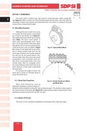
<strong>17</strong>.3.3 Determination <strong>of</strong> Factors in Bending <strong>Strength</strong> Equations<br />
<strong>17</strong>.3.3.A Tooth Width, b (mm)<br />
The term b is defined as the tooth width on the pitch cone, analogous to face width<br />
<strong>of</strong> spur or helical gears. For the meshed pair, the narrower one is used for strength<br />
calculations.<br />
<strong>17</strong>.3.3.B Tooth Pr<strong>of</strong>ile Factor, Y F<br />
The tooth pr<strong>of</strong>ile factor is a function <strong>of</strong> pr<strong>of</strong>ile shift, in both the radial <strong>and</strong> axial directions.<br />
Using the equivalent (virtual) spur gear tooth number, the first step is to determine the radial<br />
tooth pr<strong>of</strong>ile factor, Y FO , from Figure <strong>17</strong>-8 for straight bevel gears <strong>and</strong> Figure <strong>17</strong>-9 for spiral<br />
bevel gears. Next, determine the axial shift factor, K, with Equation (<strong>17</strong>-33) from which the<br />
axial shift correction factor, C, can be obtained using Figure <strong>17</strong>-7. Finally, calculate Y F by<br />
Equation (<strong>17</strong>-30).<br />
Y F = CY FO (<strong>17</strong>-30)<br />
Metric<br />
0 10<br />
14<br />
15<br />
A<br />
T-<strong>17</strong>2
ELEMENTS OF METRIC GEAR TECHNOLOGY<br />
Correction Factor C<br />
1.6<br />
1.5<br />
1.4<br />
1.3<br />
1.2<br />
1.1<br />
1.0<br />
0.9<br />
0.8<br />
0.7<br />
0.6<br />
0.5<br />
– 0.3 – 0.2 – 0.1 0 0.1 0.2 0.3<br />
Axial Shift Factor, K<br />
Fig. <strong>17</strong>-7 Correction Factor for Axial Shift, C<br />
PHONE: 516.328.3300 • FAX: 516.326.8827 • WWW.<strong>SDP</strong>-<strong>SI</strong>.COM<br />
Should the bevel gear pair not have any axial shift, then the coefficient C is 1, as per<br />
Figure <strong>17</strong>-7. The tooth pr<strong>of</strong>ile factor, Y F , per Equation (<strong>17</strong>-31) is simply the Y FO . This value is<br />
from Figure <strong>17</strong>-8 or <strong>17</strong>-9, depending upon whether it is a straight or spiral bevel gear pair.<br />
The graph entry parameter values are per Equation (<strong>17</strong>-32).<br />
Y F = Y FO (<strong>17</strong>-31)<br />
z<br />
⎫<br />
z v = ––––––––––<br />
cos δ cos 3 β m ⎪ ⎬ (<strong>17</strong>-32)<br />
h a – h a0<br />
⎪<br />
x = ––––––<br />
m<br />
⎪<br />
⎭<br />
where: h a = Addendum at outer end (mm)<br />
h a0 = Addendum <strong>of</strong> st<strong>and</strong>ard form (mm)<br />
m = Radial module (mm)<br />
The axial shift factor, K, is computed from the formula:<br />
1 2 (h a – h a0 ) tan α<br />
K = ––– n<br />
{s – 0.5 πm – ––––––––––––––} (<strong>17</strong>-33)<br />
m<br />
cos β m<br />
Metric<br />
0 10<br />
I<br />
R<br />
T<br />
1<br />
2<br />
3<br />
4<br />
5<br />
6<br />
7<br />
8<br />
9<br />
10<br />
11<br />
<strong>17</strong>.3.3.C Load Distribution Factor, Y ε<br />
Load distribution factor is the reciprocal <strong>of</strong> radial contact ratio.<br />
1<br />
Y ε = ––– (<strong>17</strong>-34)<br />
ε α<br />
The radial contact ratio for a straight bevel gear mesh is:<br />
⎫<br />
2<br />
√(R va1 – R 2 2 2 vb1 ) + √(R va2 – R vb2 ) – (R v1 + R v2 ) sin α<br />
ε α = ––––––––––––––––––––––––––––––––––––––––<br />
πm cos α<br />
⎪ ⎪⎪<br />
And the radial contact ratio for spiral bevel gear is: ⎬ (<strong>17</strong>-35)<br />
2<br />
√(R va1 – R 2 2 2 vb1 ) + √(R va2 – R vb2 ) – (R v1 + R v2 ) sin α t<br />
ε α = –––––––––––––––––––––––––––––––––––––––– ⎪<br />
πm cos α t<br />
⎭<br />
T-<strong>17</strong>3<br />
12<br />
13<br />
14<br />
15<br />
A
I<br />
ELEMENTS OF METRIC GEAR TECHNOLOGY<br />
R<br />
T<br />
1<br />
2<br />
3<br />
4.1<br />
4.0<br />
3.9<br />
3.8<br />
3.7<br />
3.6<br />
PHONE: 516.328.3300 • FAX: 516.326.8827 • WWW.<strong>SDP</strong>-<strong>SI</strong>.COM<br />
3.7<br />
3.6<br />
4<br />
5<br />
6<br />
7<br />
8<br />
Radial Tooth Pr<strong>of</strong>ile Factor (Form Factor) YFO<br />
3.5<br />
3.4<br />
3.3<br />
3.2<br />
3.1<br />
3.0<br />
2.9<br />
2.8<br />
2.7<br />
x = –0.2<br />
x = –0.3<br />
x = –0.4<br />
x = –0.5<br />
St<strong>and</strong>ard Pressure Angle<br />
α n = 20°<br />
Addendum h a = 1.000 m<br />
Dedendum h f = 1.188 m<br />
Corner Radius <strong>of</strong> Tool<br />
γ = 0.12 m<br />
Spiral Angle β m = 0°<br />
Metric<br />
0 10<br />
x = 0.2<br />
x = 0<br />
x = 0.1<br />
x = –0.1<br />
3.5<br />
3.4<br />
3.3<br />
3.2<br />
3.1<br />
3.0<br />
2.9<br />
2.8<br />
2.7<br />
9<br />
2.6<br />
x = 0.3<br />
2.6<br />
10<br />
2.5<br />
2.4<br />
x = 0.4<br />
2.5<br />
2.4<br />
11<br />
2.3<br />
2.2<br />
x = 0.5<br />
2.3<br />
2.2<br />
12<br />
13<br />
14<br />
2.1<br />
2.0<br />
2.0<br />
12 13 14 15 16 <strong>17</strong> 18 19 20 25 30 35 40 45 50 60 80 100 200 400 ∞<br />
Equivalent Spur Gear Number <strong>of</strong> Teeth, z v<br />
Fig. <strong>17</strong>-8 Radial Tooth Pr<strong>of</strong>ile Factor for Straight Bevel Gear<br />
2.1<br />
15<br />
A<br />
T-<strong>17</strong>4
ELEMENTS OF METRIC GEAR TECHNOLOGY<br />
I<br />
4.1<br />
4.0<br />
3.9<br />
3.8<br />
3.7<br />
3.6<br />
x = –0.2<br />
PHONE: 516.328.3300 • FAX: 516.326.8827 • WWW.<strong>SDP</strong>-<strong>SI</strong>.COM<br />
x = –0.3<br />
x = –0.4<br />
x = –0.5<br />
St<strong>and</strong>ard Pressure Angle<br />
α n = 20°<br />
Addendum h a = 0.850 m<br />
Dedendum h f = 1.038 m<br />
Corner Radius <strong>of</strong> Tool<br />
γ = 0.12 m<br />
Spiral Angle β m = 35°<br />
Metric<br />
0 10<br />
3.7<br />
3.6<br />
R<br />
T<br />
1<br />
2<br />
3<br />
3.5<br />
3.4<br />
x = –0.1<br />
3.5<br />
3.4<br />
4<br />
Radial Tooth Pr<strong>of</strong>ile Factor (Form Factor) YFO<br />
3.3<br />
3.2<br />
3.1<br />
3.0<br />
2.9<br />
2.8<br />
2.7<br />
2.6<br />
2.5<br />
x = 0.2<br />
x = 0.3<br />
x = 0.4<br />
x = 0.1<br />
x = 0<br />
3.3<br />
3.2<br />
3.1<br />
3.0<br />
2.9<br />
2.8<br />
2.7<br />
2.6<br />
2.5<br />
5<br />
6<br />
7<br />
8<br />
9<br />
2.4<br />
x = 0.5<br />
2.4<br />
10<br />
2.3<br />
2.2<br />
2.3<br />
2.2<br />
11<br />
2.1<br />
2.0<br />
12 13 14 15 16 <strong>17</strong> 18 19 20 25 30 35 40 45 50 60 80 100<br />
2.1<br />
2.0<br />
200 400 ∞<br />
Equivalent Spur Gear Number <strong>of</strong> Teeth, z v<br />
Fig. <strong>17</strong>-9 Radial Tooth Pr<strong>of</strong>ile Factor for Spiral Bevel Gear<br />
12<br />
13<br />
14<br />
15<br />
T-<strong>17</strong>5<br />
A
I<br />
R<br />
T<br />
1<br />
2<br />
3<br />
4<br />
5<br />
6<br />
7<br />
8<br />
9<br />
10<br />
11<br />
12<br />
13<br />
14<br />
15<br />
A<br />
ELEMENTS OF METRIC GEAR TECHNOLOGY<br />
T-<strong>17</strong>6<br />
PHONE: 516.328.3300 • FAX: 516.326.8827 • WWW.<strong>SDP</strong>-<strong>SI</strong>.COM<br />
z 2<br />
z 1<br />
20<br />
See Tables <strong>17</strong>-<strong>17</strong> through <strong>17</strong>-19 for some calculating examples <strong>of</strong> radial contact ratio<br />
Metric<br />
for various bevel gear pairs.<br />
0 10<br />
z 2<br />
z 1 12 15 16 18<br />
25 30 36 40 45 60<br />
Table <strong>17</strong>-<strong>17</strong> The Radial Contact Ratio for Gleason's Straight Bevel Gear, ε α<br />
12 15 16 18 20 25 30 36 40 45 60<br />
12<br />
15<br />
1.514<br />
1.529 1.572<br />
Σ = 90°, α = 20°<br />
16<br />
18<br />
20<br />
25<br />
30<br />
36<br />
40<br />
45<br />
60<br />
1.529<br />
1.528<br />
1.525<br />
1.518<br />
1.512<br />
1.508<br />
1.506<br />
1.503<br />
1.500<br />
1.578<br />
1.584<br />
1.584<br />
1.577<br />
1.570<br />
1.563<br />
1.559<br />
1.556<br />
1.549<br />
1.588<br />
1.597<br />
1.599<br />
1.595<br />
1.587<br />
1.579<br />
1.575<br />
1.571<br />
1.564<br />
1.616<br />
1.624<br />
1.625<br />
1.618<br />
1.609<br />
1.605<br />
1.600<br />
1.591<br />
1.640<br />
1.650<br />
1.645<br />
1.637<br />
1.632<br />
1.626<br />
1.615<br />
1.689<br />
1.697<br />
1.692<br />
1.688<br />
1.681<br />
1.668<br />
1.725<br />
1.732<br />
1.730<br />
1.725<br />
1.710<br />
1.758<br />
1.763<br />
1.763<br />
1.751<br />
1.775<br />
1.781<br />
1.773<br />
1.794<br />
1.796 1.833<br />
Table <strong>17</strong>-18 The Radial Contact Ratio for St<strong>and</strong>ard Bevel Gear, ε α<br />
z 2<br />
z 1 12 15 16 18 20 25 30 36 40 45 60<br />
12<br />
15<br />
1.514<br />
1.545 1.572<br />
Σ = 90°, α = 20°<br />
16<br />
18<br />
20<br />
25<br />
30<br />
36<br />
40<br />
45<br />
60<br />
1.554<br />
1.571<br />
1.585<br />
1.614<br />
1.634<br />
1.651<br />
1.659<br />
1.666<br />
1.680<br />
1.580<br />
1.595<br />
1.608<br />
1.636<br />
1.656<br />
1.674<br />
1.683<br />
1.691<br />
1.707<br />
1.588<br />
1.602<br />
1.615<br />
1.643<br />
1.663<br />
1.681<br />
1.689<br />
1.698<br />
1.714<br />
1.616<br />
1.628<br />
1.655<br />
1.675<br />
1.692<br />
1.702<br />
1.711<br />
1.728<br />
1.640<br />
1.666<br />
1.685<br />
1.703<br />
1.712<br />
1.721<br />
1.739<br />
1.689<br />
1.707<br />
1.725<br />
1.734<br />
1.743<br />
1.762<br />
1.725<br />
1.742<br />
1.751<br />
1.760<br />
1.780<br />
1.758<br />
1.767<br />
1.776<br />
1.796<br />
1.775<br />
1.785<br />
1.804<br />
1.794<br />
1.813 1.833<br />
Table <strong>17</strong>-19 The Radial Contact Ratio for Gleason's Spiral Bevel Gear, ε α<br />
12<br />
15<br />
16<br />
18<br />
20<br />
25<br />
30<br />
36<br />
40<br />
45<br />
60<br />
1.221<br />
1.228<br />
1.227<br />
1.225<br />
1.221<br />
1.214<br />
1.209<br />
1.204<br />
1.202<br />
1.201<br />
1.197<br />
1.254<br />
1.258<br />
1.260<br />
1.259<br />
1.253<br />
1.246<br />
1.240<br />
1.238<br />
1.235<br />
1.230<br />
1.264<br />
1.269<br />
1.269<br />
1.263<br />
1.257<br />
1.251<br />
1.248<br />
1.245<br />
1.239<br />
1.280<br />
1.284<br />
1.282<br />
1.276<br />
1.270<br />
1.266<br />
1.263<br />
1.256<br />
1.293<br />
1.297<br />
1.293<br />
1.286<br />
1.283<br />
1.279<br />
1.271<br />
Σ = 90°, α n = 20°, β m = 35°<br />
1.319<br />
1.323<br />
1.319<br />
1.316<br />
1.312<br />
1.303<br />
1.338<br />
1.341<br />
1.340<br />
1.336<br />
1.327<br />
1.355<br />
1.358<br />
1.357<br />
1.349<br />
1.364<br />
1.366<br />
1.361<br />
1.373<br />
1.373<br />
1.392
ELEMENTS OF METRIC GEAR TECHNOLOGY<br />
PHONE: 516.328.3300 • FAX: 516.326.8827 • WWW.<strong>SDP</strong>-<strong>SI</strong>.COM<br />
<strong>17</strong>.3.3.D Spiral Angle Factor, Y β<br />
The spiral angle factor is a function <strong>of</strong> the spiral angle. The value is arbitrarily set<br />
by the following conditions:<br />
β<br />
When 0 ≤ β m<br />
m ≤ 30°, Y β = 1 – –––– ⎫<br />
120 ⎪ ⎬ (<strong>17</strong>-36)<br />
⎪<br />
When β m ≥ 30°, Y β = 0.75 ⎭<br />
<strong>17</strong>.3.3.E Cutter Diameter Effect Factor, Y C<br />
This factor <strong>of</strong> cutter diameter, Y C , can be obtained from Table <strong>17</strong>-20 by the value <strong>of</strong><br />
tooth flank length, b / cos β m (mm), over cutter diameter. If cutter diameter is not known,<br />
assume Y C = 1.00.<br />
Types <strong>of</strong> Bevel <strong>Gears</strong><br />
Straight Bevel <strong>Gears</strong><br />
Spiral <strong>and</strong> Zerol Bevel <strong>Gears</strong><br />
Table <strong>17</strong>-20 Cutter Diameter Effect Factor, Y C<br />
∞<br />
1.15<br />
–––<br />
Relative Size <strong>of</strong> Cutter Diameter<br />
6 Times<br />
Tooth<br />
Width<br />
5 Times<br />
Tooth<br />
Width<br />
4 Times<br />
Tooth<br />
Width<br />
<strong>17</strong>.3.3.F Life Factor, K L<br />
We can choose a proper life factor, K L , from Table <strong>17</strong>-2 similarly to calculating the<br />
bending strength <strong>of</strong> spur <strong>and</strong> helical gears.<br />
<strong>17</strong>.3.3.G Dimension Factor Of Root Bending Stress, K FX<br />
This is a size factor that is a function <strong>of</strong> the radial module, m. Refer to Table <strong>17</strong>-21<br />
for values.<br />
–––<br />
1.00<br />
–––<br />
0.95<br />
Table <strong>17</strong>-21 Dimension Factor for Bending <strong>Strength</strong>, K FX<br />
Radial Module at<br />
Outside Diameter, m<br />
1.5 to 5<br />
above 5 to 7<br />
above 7 to 9<br />
above 9 to 11<br />
above 11 to 13<br />
above 13 to 15<br />
above 15 to <strong>17</strong><br />
above <strong>17</strong> to 19<br />
above 19 to 22<br />
above 22 to 25<br />
<strong>Gears</strong> Without<br />
Hardened Surface<br />
1.0<br />
0.99<br />
0.98<br />
0.97<br />
0.96<br />
0.94<br />
0.93<br />
0.92<br />
0.90<br />
0.88<br />
–––<br />
0.90<br />
<strong>Gears</strong> With<br />
Hardened Surface<br />
1.0<br />
0.98<br />
0.96<br />
0.94<br />
0.92<br />
0.90<br />
0.88<br />
0.86<br />
0.83<br />
0.80<br />
Metric<br />
0 10<br />
I<br />
R<br />
T<br />
1<br />
2<br />
3<br />
4<br />
5<br />
6<br />
7<br />
8<br />
9<br />
10<br />
11<br />
12<br />
13<br />
14<br />
15<br />
T-<strong>17</strong>7<br />
A
I<br />
R<br />
T<br />
1<br />
2<br />
3<br />
4<br />
5<br />
6<br />
7<br />
8<br />
9<br />
10<br />
11<br />
12<br />
ELEMENTS OF METRIC GEAR TECHNOLOGY<br />
PHONE: 516.328.3300 • FAX: 516.326.8827 • WWW.<strong>SDP</strong>-<strong>SI</strong>.COM<br />
<strong>17</strong>.3.3.H Tooth Flank Load Distribution Factor, K M<br />
Tooth flank load distribution factor, K M , is obtained from Table <strong>17</strong>-22 or Table <strong>17</strong>-23.<br />
Table <strong>17</strong>-22 Tooth Flank Load Distribution, K M , for Spiral Bevel <strong>Gears</strong>,<br />
Zerol Bevel <strong>Gears</strong> <strong>and</strong> Straight Bevel <strong>Gears</strong> with Crowning<br />
Stiffness <strong>of</strong> Shaft, Gear<br />
Box, etc.<br />
Very Stiff<br />
Average<br />
Somewhat Weak<br />
Table <strong>17</strong>-23 Tooth Flank Load Distribution Factor, K M , for<br />
Straight Bevel <strong>Gears</strong> without Crowning<br />
Stiffness <strong>of</strong> Shaft, Gear<br />
Box, etc.<br />
Very Stiff<br />
Average<br />
Somewhat Weak<br />
Both <strong>Gears</strong><br />
Supported<br />
on Two Sides<br />
1.05<br />
1.6<br />
2.2<br />
One Gear<br />
Supported<br />
on One End<br />
Both <strong>Gears</strong><br />
Supported<br />
on One End<br />
<strong>17</strong>.3.3.I Dynamic Load Factor, K V<br />
Dynamic load factor, K V , is a function <strong>of</strong> the precision grade <strong>of</strong> the gear <strong>and</strong> the<br />
tangential speed at the outer pitch circle, as shown in Table <strong>17</strong>-24.<br />
Precision<br />
Grade<br />
<strong>of</strong> <strong>Gears</strong><br />
from<br />
JIS B <strong>17</strong>02<br />
1<br />
2<br />
3<br />
4<br />
5<br />
6<br />
Up to 1<br />
1.0<br />
1.0<br />
1.0<br />
1.1<br />
1.2<br />
1.4<br />
Both <strong>Gears</strong><br />
Supported<br />
on Two Sides<br />
1.2<br />
1.4<br />
1.55<br />
One Gear<br />
Supported<br />
on One End<br />
1.35<br />
1.6<br />
1.75<br />
1.15<br />
1.8<br />
2.5<br />
Table <strong>17</strong>-24 Dynamic Load Factor, K V<br />
Tangential Speed at Outer Pitch Circle (m/s)<br />
Above 1<br />
to 3<br />
1.1<br />
1.2<br />
1.3<br />
1.4<br />
1.5<br />
1.7<br />
Above 3<br />
to 5<br />
1.15<br />
1.3<br />
1.4<br />
1.5<br />
1.7<br />
Above 5<br />
to 8<br />
1.2<br />
1.4<br />
1.5<br />
1.7<br />
Above 8<br />
to 12<br />
1.3<br />
1.5<br />
1.7<br />
Both <strong>Gears</strong><br />
Supported<br />
on One End<br />
Above 12<br />
to 18<br />
1.5<br />
1.7<br />
1.5<br />
1.8<br />
2.0<br />
1.35<br />
2.1<br />
2.8<br />
Above 18<br />
to 25<br />
1.7<br />
Metric<br />
0 10<br />
13<br />
14<br />
15<br />
A<br />
T-<strong>17</strong>8
ELEMENTS OF METRIC GEAR TECHNOLOGY<br />
<strong>17</strong>.3.3.K Reliability Factor, K R<br />
The reliability factor should be assumed to be as follows:<br />
1. General case: K R = 1.2<br />
2. When all other factors can be determined accurately:<br />
K R = 1.0<br />
3. When all or some <strong>of</strong> the factors cannot be known with certainty:<br />
K R = 1.4<br />
PHONE: 516.328.3300 • FAX: 516.326.8827 • WWW.<strong>SDP</strong>-<strong>SI</strong>.COM<br />
<strong>17</strong>.3.3.L Allowable Bending Stress at Root, σ F lim<br />
The allowable stress at root σ F lim can be obtained from Tables <strong>17</strong>-5 through <strong>17</strong>-8,<br />
similar to the case <strong>of</strong> spur <strong>and</strong> helical gears.<br />
<strong>17</strong>.3.4 Examples <strong>of</strong> Bevel Gear Bending <strong>Strength</strong> Calculations<br />
Table <strong>17</strong>-24A Gleason Straight Bevel Gear Design Details<br />
No. Item Symbol Unit Pinion Gear<br />
Σ<br />
m<br />
degree<br />
mm<br />
90°<br />
2<br />
α<br />
20°<br />
degree<br />
β m<br />
0°<br />
z<br />
1<br />
2<br />
3<br />
4<br />
5<br />
6<br />
7<br />
8<br />
9<br />
10<br />
11<br />
12<br />
13<br />
14<br />
15<br />
16<br />
<strong>17</strong><br />
18<br />
19<br />
20<br />
21<br />
22<br />
Shaft Angle<br />
Module<br />
Pressure Angle<br />
Central Spiral Angle<br />
Number <strong>of</strong> Teeth<br />
Pitch Circle Diameter<br />
Pitch Cone Angle<br />
Cone Distance<br />
Tooth Width<br />
Central Pitch Circle Diameter<br />
Precision Grade<br />
Manufacturing Method<br />
Surface Roughness<br />
Revolutions per Minute<br />
Linear Speed<br />
Direction <strong>of</strong> Load<br />
Duty Cycle<br />
Material<br />
Heat Treatment<br />
Surface Hardness<br />
Core Hardness<br />
Effective Carburized Depth<br />
d<br />
δ<br />
Re<br />
b<br />
d m<br />
n<br />
v<br />
mm<br />
degree<br />
mm<br />
rpm<br />
m/s<br />
cycle<br />
mm<br />
20<br />
40<br />
40.000<br />
80.000<br />
26.56505°<br />
63.43495°<br />
44.721<br />
15<br />
33.292<br />
66.584<br />
JIS 3<br />
JIS 3<br />
Gleason No. 104<br />
12.5 µm<br />
1500<br />
3.142<br />
Unidirectional<br />
More than 10 7 cycles<br />
SCM 415<br />
Carburized<br />
HV 600 … 640<br />
HB 260 … 280<br />
0.3 … 0.5<br />
Metric<br />
0 10<br />
12.5 µm<br />
750<br />
I<br />
R<br />
T<br />
1<br />
2<br />
3<br />
4<br />
5<br />
6<br />
7<br />
8<br />
9<br />
10<br />
11<br />
12<br />
13<br />
14<br />
15<br />
T-<strong>17</strong>9<br />
A
I<br />
R<br />
T<br />
1<br />
2<br />
3<br />
4<br />
5<br />
6<br />
7<br />
8<br />
9<br />
10<br />
11<br />
12<br />
13<br />
14<br />
ELEMENTS OF METRIC GEAR TECHNOLOGY<br />
PHONE: 516.328.3300 • FAX: 516.326.8827 • WWW.<strong>SDP</strong>-<strong>SI</strong>.COM<br />
Table <strong>17</strong>-24B Bending <strong>Strength</strong> Factors for Gleason Straight Bevel Gear<br />
No. Item Symbol Unit Pinion Gear<br />
1 Central Spiral Angle<br />
β m degree<br />
0°<br />
2 Allowable Bending Stress at Root<br />
σ F lim kgf/mm 2 42.5<br />
42.5<br />
3 Module<br />
m<br />
2<br />
4 Tooth Width<br />
b mm<br />
15<br />
5 Cone Distance<br />
R e<br />
44.721<br />
6 Tooth Pr<strong>of</strong>ile Factor<br />
Y F<br />
2.369<br />
2.387<br />
7 Load Distribution Factor<br />
Y ε<br />
0.613<br />
8 Spiral Angle Factor<br />
Y β<br />
1.0<br />
9 Cutter Diameter Effect Factor<br />
Y C<br />
1.15<br />
10 Life Factor<br />
K L<br />
1.0<br />
11 Dimension Factor<br />
K FX<br />
1.0<br />
12 Tooth Flank Load Distribution Factor<br />
K M<br />
1.8<br />
1.8<br />
13 Dynamic Load Factor<br />
K V<br />
1.4<br />
14 Overload Factor<br />
K O<br />
1.0<br />
15 Reliability Factor<br />
K R<br />
1.2<br />
16<br />
Allowable Tangential Force at<br />
Central Pitch Circle<br />
F t lim kgf <strong>17</strong>8.6<br />
<strong>17</strong>7.3<br />
<strong>17</strong>.4 Surface <strong>Strength</strong> Of Bevel <strong>Gears</strong><br />
This information is valid for bevel gears which are used in power transmission in<br />
general industrial machines. The applicable ranges are:<br />
Radial Module: m 1.5 to 25 mm<br />
Pitch Diameter: d Straight bevel gear under 1600 mm<br />
Spiral bevel gear under 1000 mm<br />
Linear Speed: v less than 25 m/sec<br />
Rotating Speed: n less than 3600 rpm<br />
<strong>17</strong>.4.1 Basic Conversion Formulas<br />
The same formulas <strong>of</strong> SECTION <strong>17</strong>.3 apply. (See page T-<strong>17</strong>1).<br />
<strong>17</strong>.4.2 Surface <strong>Strength</strong> Equations<br />
In order to obtain a proper surface strength, the tangential force at the central pitch<br />
circle, F tm , must remain below the allowable tangential force at the central pitch circle,<br />
F tm lim , based on the allowable Hertz stress σ H lim .<br />
F tm ≤ F tm lim (<strong>17</strong>-37)<br />
Alternately, the Hertz stress σ H , which is derived from the tangential force at the central<br />
pitch circle must be smaller than the allowable Hertz stress σ H lim.<br />
σ H ≤ σ H lim (<strong>17</strong>-38)<br />
15<br />
A<br />
T-180
ELEMENTS OF METRIC GEAR TECHNOLOGY<br />
PHONE: 516.328.3300 • FAX: 516.326.8827 • WWW.<strong>SDP</strong>-<strong>SI</strong>.COM<br />
The allowable tangential force at the central pitch circle, F tm lim , in kgf can be calculated<br />
from Equation (<strong>17</strong>-39).<br />
σ H lim d 1 R e – 0.5 b u 2<br />
F tm lim = [(–––––) 2 ––––– ––––––––– b ––––– ]<br />
Z M cos δ 1 R e u 2 + 1<br />
K HL Z L Z R Z V Z W K HX 1 1<br />
• [(–––––––––––––––) 2 ––––––– –––– ] (<strong>17</strong>-39)<br />
Z H Z ε Z β K H β K V K O C R<br />
2<br />
The Hertz stress, σ H (kgf/mm 2 ) is calculated from Equation (<strong>17</strong>-40).<br />
––––––––––––––––––––––––<br />
cos δ 1 F tm u 2 + 1 R<br />
σ e<br />
H =–––––––– –––––– ––––––––<br />
d 1 b u 2 R e – 0.5 b<br />
––––––––––<br />
Z H Z M Z ε Z β<br />
•[–––––––––––––– K Hβ K V K O C R ] (<strong>17</strong>-40)<br />
K HL Z L Z R Z V Z W K HX<br />
<strong>17</strong>.4.3 Determination <strong>of</strong> Factors In Surface <strong>Strength</strong> Equations<br />
<strong>17</strong>.4.3.A Tooth Width, b (mm)<br />
This term is defined as the tooth width on the pitch cone. For a meshed pair, the<br />
narrower gear's "b " is used for strength calculations.<br />
<strong>17</strong>.4.3.B Zone Factor, Z H<br />
The zone factor is defined as:<br />
––––––––––<br />
2 cos β<br />
Z b<br />
H = –––––––––– (<strong>17</strong>-41)<br />
sin α t cos α t<br />
where: b m = Central spiral angle<br />
a n = Normal pressure angle<br />
tan α<br />
a n<br />
t = Central radial pressure angle = tan –1 (–––––––)<br />
cos β m<br />
b b = tan –1 (tan β m cos α t )<br />
If the normal pressure angle α n is 20°, 22.5° or 25°, the zone factor can be obtained from<br />
Figure <strong>17</strong>-10.<br />
2.6<br />
2.5<br />
2.4<br />
2.3<br />
α n = 20°<br />
α n = 22.5°<br />
α n = 25°<br />
Metric<br />
0 10<br />
I<br />
R<br />
T<br />
1<br />
2<br />
3<br />
4<br />
5<br />
6<br />
7<br />
8<br />
9<br />
10<br />
11<br />
Zone Factor ZH<br />
2.2<br />
2.1<br />
2.0<br />
1.9<br />
12<br />
13<br />
14<br />
1.8<br />
1.7<br />
0° 5° 10° 15° 20° 25° 30° 35° 40° 45°<br />
Spiral Angle at Central Position β m<br />
Fig. <strong>17</strong>-10 Zone Factor, Z H<br />
T-181<br />
15<br />
A
I<br />
R<br />
T<br />
1<br />
2<br />
3<br />
4<br />
5<br />
6<br />
7<br />
8<br />
9<br />
10<br />
ELEMENTS OF METRIC GEAR TECHNOLOGY<br />
where:<br />
<strong>17</strong>.4.3.C Material Factor, Z M<br />
The material factor, Z M , is obtainable from Table <strong>17</strong>-9.<br />
<strong>17</strong>.4.3.D Contact Ratio Factor, Z ε<br />
The contact ratio factor is calculated from the equations below.<br />
PHONE: 516.328.3300 • FAX: 516.326.8827 • WWW.<strong>SDP</strong>-<strong>SI</strong>.COM<br />
Straight bevel gear: Z ε = 1.0<br />
⎫ Spiral bevel gear:<br />
⎪ –––––––––– ε β<br />
⎪<br />
when ε α ≤ 1, Z ε = 1 – ε β + –– ε α<br />
⎬ (<strong>17</strong>-42)<br />
⎪ ––– 1 when ε β > 1, Z ε = –––<br />
⎪<br />
⎭<br />
ε α<br />
ε α = Radial Contact Ratio<br />
e β = Overlap Ratio<br />
<strong>17</strong>.4.3.E Spiral Angle Factor, Z β<br />
Little is known about these factors, so usually it is assumed to be unity.<br />
Z β = 1.0 (<strong>17</strong>-43)<br />
<strong>17</strong>.4.3.F Life Factor, K HL<br />
The life factor for surface strength is obtainable from Table <strong>17</strong>-10.<br />
<strong>17</strong>.4.3.G Lubricant Factor, Z L<br />
The lubricant factor, Z L , is found in Figure <strong>17</strong>-3.<br />
<strong>17</strong>.4.3.H Surface Roughness Factor, Z R<br />
The surface roughness factor is obtainable from Figure <strong>17</strong>-11 on the basis <strong>of</strong> average<br />
roughness, R maxm , in µ m. The average surface roughness is calculated by Equation (<strong>17</strong>-<br />
44) from the surface roughnesses <strong>of</strong> the pinion <strong>and</strong> gear (R max1 <strong>and</strong> R max 2 ), <strong>and</strong> the center<br />
distance, a, in mm.<br />
–––––<br />
R max 1 + R max 2 100<br />
R maxm = –––––––––––– ––––– 3 (µ m) (<strong>17</strong>-44)<br />
2 a<br />
where: a = R m (sin δ 1 + cos δ 1 )<br />
b<br />
R m = R e – –––<br />
2<br />
Metric<br />
0 10<br />
11<br />
12<br />
13<br />
14<br />
Surface Roughness Factor, ZR<br />
1.1<br />
1.0<br />
0.9<br />
0.8<br />
0.7<br />
Normalized Gear<br />
Surface Hardened Gear<br />
1 5 10 15 20 25<br />
Average Surface Roughness, R max m (µ m)<br />
Fig. <strong>17</strong>-11 Surface Roughness Factor, Z R<br />
15<br />
A<br />
T-182
ELEMENTS OF METRIC GEAR TECHNOLOGY<br />
PHONE: 516.328.3300 • FAX: 516.326.8827 • WWW.<strong>SDP</strong>-<strong>SI</strong>.COM<br />
<strong>17</strong>.4.3.I Sliding Speed Factor, Z V<br />
The sliding speed factor is obtained from Figure <strong>17</strong>-5 based on the pitch circle linear<br />
speed.<br />
<strong>17</strong>.4.3.J Hardness Ratio Factor, Z W<br />
The hardness ratio factor applies only to the gear that is in mesh with a pinion which<br />
is quenched <strong>and</strong> ground. The ratio is calculated by Equation (<strong>17</strong>-45).<br />
HB 2 – 130<br />
Z W = 1.2 – –––––––– (<strong>17</strong>-45)<br />
<strong>17</strong>00<br />
where Brinell hardness <strong>of</strong> the gear is: 130 ≤ HB 2 ≤ 470<br />
If the gear's hardness is outside <strong>of</strong> this range, Z W is assumed to be unity.<br />
Z W = 1.0 (<strong>17</strong>-46)<br />
<strong>17</strong>.4.3.K Dimension Factor, K HX<br />
Since, <strong>of</strong>ten, little is known about this factor, it is assumed to be unity.<br />
K HX = 1.0 (<strong>17</strong>-47)<br />
<strong>17</strong>.4.3.L Tooth Flank Load Distribution Factor, K H β<br />
Factors are listed in Tables <strong>17</strong>-25 <strong>and</strong> <strong>17</strong>-26. If the gear <strong>and</strong> pinion are unhardened,<br />
the factors are to be reduced to 90% <strong>of</strong> the values in the table.<br />
Metric<br />
0 10<br />
I<br />
R<br />
T<br />
1<br />
2<br />
3<br />
4<br />
5<br />
6<br />
Table <strong>17</strong>-25 Tooth Flank Load Distribution Factor for Spiral Bevel <strong>Gears</strong>, Zerol<br />
Bevel <strong>Gears</strong> <strong>and</strong> Straight Bevel <strong>Gears</strong> with Crowning, K H β<br />
Stiffness <strong>of</strong> Shaft,<br />
Gear Box, etc.<br />
Very Stiff<br />
Average<br />
Somewhat Weak<br />
Both <strong>Gears</strong><br />
Supported<br />
on Two Sides<br />
1.3<br />
1.6<br />
1.75<br />
One Gear<br />
Supported<br />
on One End<br />
1.5<br />
1.85<br />
Both <strong>Gears</strong><br />
Supported<br />
on One End<br />
Table <strong>17</strong>-26 Tooth Flank Load Distribution Factor for Straight Bevel<br />
Gear without Crowning, K H β<br />
Stiffness <strong>of</strong> Shaft,<br />
Gear Box, etc.<br />
Very Stiff<br />
Average<br />
Somewhat Weak<br />
Both <strong>Gears</strong><br />
Supported<br />
on Two Sides<br />
1.3<br />
1.85<br />
2.8<br />
2.1<br />
One Gear<br />
Supported<br />
on One End<br />
1.5<br />
2.1<br />
3.3<br />
1.7<br />
2.1<br />
2.5<br />
Both <strong>Gears</strong><br />
Supported<br />
on One End<br />
1.7<br />
2.6<br />
3.8<br />
7<br />
8<br />
9<br />
10<br />
11<br />
12<br />
13<br />
14<br />
15<br />
T-183<br />
A
I<br />
R<br />
T<br />
1<br />
2<br />
3<br />
4<br />
5<br />
6<br />
7<br />
8<br />
9<br />
10<br />
11<br />
ELEMENTS OF METRIC GEAR TECHNOLOGY<br />
<strong>17</strong>.4.3.M Dynamic Load Factor, K V<br />
The dynamic load factor can be obtained from Table <strong>17</strong>-24.<br />
PHONE: 516.328.3300 • FAX: 516.326.8827 • WWW.<strong>SDP</strong>-<strong>SI</strong>.COM<br />
<strong>17</strong>.4.3.N Overload Factor, K O<br />
The overload factor can be computed by Equation <strong>17</strong>-11 or found in Table <strong>17</strong>-4.<br />
<strong>17</strong>.4.3.O Reliability Factor, C R<br />
The general practice is to assume C R to be at least 1.15.<br />
<strong>17</strong>.4.3.P Allowable Hertz Stress, σ H lim<br />
The values <strong>of</strong> allowable Hertz stress are given in Tables <strong>17</strong>-12 through <strong>17</strong>-16.<br />
<strong>17</strong>.4.4 Examples Of Bevel Gear Surface <strong>Strength</strong> Calculation<br />
No. Item Symbol Unit Pinion Gear<br />
Σ<br />
m<br />
degree<br />
mm<br />
90°<br />
2<br />
α<br />
20°<br />
degree<br />
β m<br />
0°<br />
z<br />
20<br />
d<br />
mm 40.000<br />
δ degree 26.56505°<br />
R e<br />
b<br />
mm<br />
44.721<br />
15<br />
d m<br />
1<br />
2<br />
3<br />
4<br />
5<br />
6<br />
7<br />
8<br />
9<br />
10<br />
11<br />
12<br />
13<br />
14<br />
15<br />
16<br />
<strong>17</strong><br />
18<br />
19<br />
20<br />
21<br />
22<br />
Shaft Angle<br />
Module<br />
Pressure Angle<br />
Central Spiral Angle<br />
Number <strong>of</strong> Teeth<br />
Pitch Circle Diameter<br />
Pitch Cone Angle<br />
Cone Distance<br />
Tooth Width<br />
Central Pitch Circle Diameter<br />
Precision Grade<br />
Manufacturing Method<br />
Surface Roughness<br />
Revolutions per Minute<br />
Linear Speed<br />
Direction <strong>of</strong> Load<br />
Duty Cycle<br />
Material<br />
Heat Treatment<br />
Surface Hardness<br />
Core Hardness<br />
Effective Carburized Depth<br />
Table <strong>17</strong>-26A Gleason Straight Bevel Gear Design Details<br />
n<br />
v<br />
rpm<br />
m/s<br />
cycle<br />
mm<br />
33.292<br />
JIS 3<br />
12.5 µ m<br />
1500<br />
Metric<br />
0 10<br />
Gleason No. 104<br />
3.142<br />
Unidirectional<br />
Over 10 7 cycles<br />
SCM 415<br />
Carburized<br />
HV 600 … 640<br />
HB 260 … 280<br />
0.3 … 0.5<br />
40<br />
80.000<br />
63.43495°<br />
66.584<br />
JIS 3<br />
12.5 µ m<br />
750<br />
12<br />
13<br />
14<br />
15<br />
A<br />
T-184
ELEMENTS OF METRIC GEAR TECHNOLOGY<br />
PHONE: 516.328.3300 • FAX: 516.326.8827 • WWW.<strong>SDP</strong>-<strong>SI</strong>.COM<br />
Table <strong>17</strong>-26B Surface <strong>Strength</strong> Factors <strong>of</strong> Gleason Straight Bevel Gear<br />
164<br />
No. Item Symbol Unit Pinion Gear<br />
1 Allowable Hertz Stress<br />
σ H lim kgf/mm 2<br />
21<br />
Allowable Tangential Force on<br />
F t lim kgf<br />
103.0<br />
Central Pitch Circle<br />
103.0<br />
2<br />
3<br />
Pinion's Pitch Diameter<br />
Pinion's Pitch Cone Angle<br />
d 1<br />
δ 1<br />
mm<br />
degree<br />
40.000<br />
26.56505°<br />
4 Cone Distance<br />
R e<br />
44.721<br />
mm<br />
5 Tooth Width<br />
b<br />
15<br />
6<br />
7<br />
8<br />
9<br />
10<br />
11<br />
12<br />
13<br />
14<br />
15<br />
16<br />
<strong>17</strong><br />
18<br />
19<br />
20<br />
Numbers <strong>of</strong> Teeth Ratio z 2 / z 1<br />
Zone Factor<br />
Material Factor<br />
Contact Ratio Factor<br />
Spiral Angle Factor<br />
Life Factor<br />
Lubricant Factor<br />
Surface Roughness Factor<br />
Sliding Speed Factor<br />
Hardness Ratio Factor<br />
Dimension Factor <strong>of</strong> Root Stress<br />
Load Distribution Factor<br />
Dynamic Load Factor<br />
Overload Factor<br />
Reliability Factor<br />
u<br />
Z H<br />
Z M<br />
Z ε<br />
Z β<br />
K HL<br />
Z L<br />
Z R<br />
Z V<br />
Z W<br />
K HX<br />
K H β<br />
K V<br />
K O<br />
C R<br />
(kgf/mm 2 ) 0.5<br />
2<br />
2.495<br />
60.6<br />
1.0<br />
1.0<br />
1.0<br />
1.0<br />
0.90<br />
0.97<br />
1.0<br />
1.0<br />
2.1<br />
1.4<br />
1.0<br />
1.15<br />
<strong>17</strong>.5 <strong>Strength</strong> Of Worm Gearing<br />
This information is applicable for worm gear drives that are used to transmit power<br />
in general industrial machines with the following parameters:<br />
Axial Module: m x 1 to 25 mm<br />
Pitch Diameter <strong>of</strong> Worm Gear: d 2 less than 900 mm<br />
Sliding Speed: v s less than 30 m/sec<br />
Rotating Speed, Worm Gear: n 2 less than 600 rpm<br />
<strong>17</strong>.5.1 Basic Formulas:<br />
Sliding Speed, v s (m/s)<br />
d 1 n<br />
v 1<br />
s = ––––––––––– (<strong>17</strong>-48)<br />
19100 cos γ<br />
I<br />
R<br />
T<br />
1<br />
2<br />
3<br />
4<br />
5<br />
6<br />
7<br />
8<br />
9<br />
10<br />
11<br />
12<br />
13<br />
14<br />
15<br />
T-185<br />
A
I<br />
R<br />
T<br />
1<br />
2<br />
3<br />
4<br />
5<br />
6<br />
7<br />
8<br />
9<br />
10<br />
11<br />
12<br />
ELEMENTS OF METRIC GEAR TECHNOLOGY<br />
<strong>17</strong>.5.2 Torque, Tangential Force <strong>and</strong> Efficiency<br />
(1) Worm as Driver Gear (Speed Reducing)<br />
PHONE: 516.328.3300 • FAX: 516.326.8827 • WWW.<strong>SDP</strong>-<strong>SI</strong>.COM<br />
F t d 2<br />
⎫<br />
T 2 = ––––––<br />
2000 ⎪ T 2 F t d 2 T 1 = –––– = –––––––––<br />
u η R 2000 u η R ⎪ ⎬ (<strong>17</strong>-49)<br />
µ tan γ (1 – tan γ ––––––) cos α n<br />
η R = ––––––––––––––––––––<br />
µ tan γ + ––––––<br />
⎪<br />
cos α n<br />
⎭<br />
where: T 2 = Nominal torque <strong>of</strong> worm gear (kg • m)<br />
T 1 = Nominal torque <strong>of</strong> worm (kgf • m)<br />
F t = Nominal tangential force on worm gear's pitch circle (kgf)<br />
d 2 = Pitch diameter <strong>of</strong> worm gear (mm)<br />
u = Teeth number ratio = z 2 /z w<br />
η R = Transmission efficiency, worm driving (not including bearing loss, lubricant<br />
agitation loss, etc.)<br />
µ = Friction coefficient<br />
(2) Worm Gear as Driver Gear (Speed Increasing)<br />
F t d 2<br />
⎫<br />
T 2 = ––––––<br />
2000 ⎪ T 2 η I F t d 2 η I T 1 = –––– = –––––<br />
u 2000 u ⎪ ⎬ (<strong>17</strong>-50)<br />
µ tan γ – ––––––<br />
cos α n<br />
η I = ––––––––––––––––––––<br />
µ tan γ (1 + tan γ ––––––)<br />
⎪<br />
cos α n<br />
⎭<br />
where: η I = Transmission efficiency, worm gear driving (not including bearing loss,<br />
lubricant agitation loss, etc.)<br />
<strong>17</strong>.5.3 Friction Coefficient, µ<br />
The friction factor varies as sliding speed changes. The combination <strong>of</strong> materials<br />
is important. For the case <strong>of</strong> a worm that is carburized <strong>and</strong> ground, <strong>and</strong> mated with a<br />
phosphorous bronze worm gear, see Figure <strong>17</strong>-12. For some other materials, see Table <strong>17</strong>-<br />
27.<br />
For lack <strong>of</strong> data, friction coefficient <strong>of</strong> materials not listed in Table <strong>17</strong>-27 are very<br />
difficult to obtain. H.E. Merritt has <strong>of</strong>fered some further information on this topic. See<br />
Reference 9.<br />
Metric<br />
0 10<br />
13<br />
14<br />
15<br />
A<br />
T-186
ELEMENTS OF METRIC GEAR TECHNOLOGY<br />
I<br />
Coefficient <strong>of</strong> Friction<br />
0.150<br />
0.120<br />
0.100<br />
0.090<br />
0.080<br />
0.070<br />
0.060<br />
0.050<br />
0.040<br />
0.030<br />
0.020<br />
0.015<br />
PHONE: 516.328.3300 • FAX: 516.326.8827 • WWW.<strong>SDP</strong>-<strong>SI</strong>.COM<br />
R<br />
T<br />
1<br />
2<br />
3<br />
4<br />
0.012<br />
0 0.001 0.01 0.05 0.1 0.2 0.4 0.6 1 1.5 2 3 4 5 6 7 8 9 10 12 14 16 18 20 22 24 26 30<br />
Sliding Speed<br />
Fig. <strong>17</strong>-12 Friction Coefficient, µ<br />
Table <strong>17</strong>-27 Combinations <strong>of</strong> Materials <strong>and</strong> Their Coefficients <strong>of</strong> Friction, µ<br />
Combination <strong>of</strong> Materials<br />
Cast Iron <strong>and</strong> Phosphor Bronze<br />
Cast Iron <strong>and</strong> Cast Iron<br />
Quenched Steel <strong>and</strong> Aluminum Alloy<br />
Steel <strong>and</strong> Steel<br />
<strong>17</strong>.5.4 Surface <strong>Strength</strong> <strong>of</strong> Worm Gearing Mesh<br />
µ<br />
µ in Figure <strong>17</strong>-12 times 1.15<br />
µ in Figure <strong>17</strong>-12 times 1.33<br />
µ in Figure <strong>17</strong>-12 times 1.33<br />
µ in Figure <strong>17</strong>-12 times 2.00<br />
(1) Calculation <strong>of</strong> Basic Load<br />
Provided dimensions <strong>and</strong> materials <strong>of</strong> the worm pair are known, the allowable load is<br />
as follows:<br />
F t lim = Allowable tangential force (kgf)<br />
Z L Z M Z<br />
0.8<br />
= 3.82 K R<br />
v K n S c lim Zd 2 m x –––––– (<strong>17</strong>-51)<br />
K C<br />
T 2 lim = Allowable worm gear torque (kgf • m)<br />
Z L Z M Z<br />
1.8<br />
= 0.00191 K R<br />
v K n S c lim Zd 2 m x ––––– (<strong>17</strong>-52)<br />
(2) Calculation <strong>of</strong> Equivalent Load<br />
The basic load Equations (<strong>17</strong>-51) <strong>and</strong> (<strong>17</strong>-52) are applicable under the conditions <strong>of</strong><br />
no impact <strong>and</strong> the pair can operate for 26000 hours minimum. The condition <strong>of</strong> "no impact"<br />
is defined as the starting torque which must be less than 200% <strong>of</strong> the rated torque; <strong>and</strong> the<br />
frequency <strong>of</strong> starting should be less than twice per hour.<br />
K C<br />
5<br />
6<br />
7<br />
8<br />
9<br />
10<br />
11<br />
12<br />
13<br />
14<br />
15<br />
T-187<br />
A
I<br />
R<br />
T<br />
1<br />
2<br />
3<br />
4<br />
5<br />
6<br />
7<br />
8<br />
9<br />
10<br />
11<br />
12<br />
13<br />
ELEMENTS OF METRIC GEAR TECHNOLOGY<br />
PHONE: 516.328.3300 • FAX: 516.326.8827 • WWW.<strong>SDP</strong>-<strong>SI</strong>.COM<br />
An equivalent load is needed to compare with the basic load in order to determine an<br />
actual design load, when the conditions deviate from the above.<br />
Metric<br />
Equivalent load is then converted to an equivalent tangential force, F te , in kgf:<br />
0 10<br />
F te = F t K h K s (<strong>17</strong>-53)<br />
<strong>and</strong> equivalent worm gear torque, T 2e , in kgf • m:<br />
T 2e = T 2 K h K s (<strong>17</strong>-54)<br />
(3) Determination <strong>of</strong> Load<br />
Under no impact condition, to have life expectancy <strong>of</strong> 26000 hours, the following<br />
relationships must be satisfied:<br />
F t ≤ F t lim or T 2 ≤ T 2 lim (<strong>17</strong>-55)<br />
For all other conditions:<br />
F te ≤ F t lim or T 2e ≤ T 2 lim (<strong>17</strong>-56)<br />
NOTE: If load is variable, the maximum load should be used as the criterion.<br />
<strong>17</strong>.5.5 Determination <strong>of</strong> Factors in Worm Gear Surface <strong>Strength</strong> Equations<br />
<strong>17</strong>.5.5.A Tooth Width <strong>of</strong> Worm Gear, b 2 (mm)<br />
Tooth width <strong>of</strong> worm gear is defined as in Figure <strong>17</strong>-13.<br />
<strong>17</strong>.5.5.B Zone Factor, Z<br />
If b 2 < 2.3 m x Q + 1 , then:<br />
⎫ ⎪⎪<br />
b 2<br />
Z = (Basic zone factor) x –––––––––––<br />
⎪<br />
2 m x Q + 1 ⎬ (<strong>17</strong>-57)<br />
If b 2 ≥ 2.3 m x Q + 1 , then:<br />
⎪ ⎪⎪<br />
Z = (Basic zone factor) x 1.15<br />
⎭<br />
where: Basic Zone Factor is obtained from Table <strong>17</strong>-28<br />
d<br />
Q : Diameter factor = ––– 1<br />
m x<br />
z w : number <strong>of</strong> worm threads<br />
b 2 b 2<br />
14<br />
15<br />
Fig. <strong>17</strong>-13 Tooth Width <strong>of</strong> Worm Gear<br />
A<br />
T-188
ELEMENTS OF METRIC GEAR TECHNOLOGY<br />
I<br />
Q<br />
z w<br />
7<br />
1<br />
1.052<br />
7.5<br />
1.065<br />
8<br />
1.084<br />
Table <strong>17</strong>-28 Basic Zone Factors<br />
8.5<br />
1.107<br />
9<br />
1.128<br />
9.5<br />
1.137<br />
10<br />
1.143<br />
11<br />
1.160<br />
PHONE: 516.328.3300 • FAX: 516.326.8827 • WWW.<strong>SDP</strong>-<strong>SI</strong>.COM<br />
12<br />
1.202<br />
13<br />
1.260<br />
14<br />
1.318<br />
<strong>17</strong><br />
1.402<br />
20<br />
1.508<br />
Metric<br />
0 10<br />
R<br />
T<br />
2<br />
1.055<br />
1.099<br />
1.144<br />
1.183<br />
1.214<br />
1.223<br />
1.231<br />
1.250<br />
1.280<br />
1.320<br />
1.360<br />
1.447<br />
1.575<br />
3<br />
4<br />
0.989<br />
0.981<br />
1.109<br />
1.098<br />
1.209<br />
1.204<br />
1.260<br />
1.301<br />
1.305<br />
1.380<br />
1.333<br />
1.428<br />
1.350<br />
1.460<br />
1.365<br />
1.490<br />
1.393<br />
1.515<br />
1.422<br />
1.545<br />
1.442<br />
1.570<br />
1.532<br />
1.666<br />
1.674<br />
1.798<br />
1<br />
Sliding Speed Factor KV<br />
<strong>17</strong>.5.5.C Sliding Speed Factor, K v<br />
The sliding speed factor is obtainable from Figure <strong>17</strong>-14, where the abscissa is the<br />
pitch line linear velocity.<br />
1.0<br />
0.9<br />
0.8<br />
0.7<br />
0.6<br />
0.5<br />
0.4<br />
0.3<br />
0.2<br />
0.1<br />
0 0.001 0.01 0.05 0.1 0.2 0.4 0.6 1 1.5 2 3 4 5 6 7 8 9 10 11 12 14 16 18 20 22 24 26 30<br />
Sliding Speed vs (m/s)<br />
Fig. <strong>17</strong>-14 Sliding Speed Factor, K v<br />
<strong>17</strong>.5.5.D Rotating Speed Factor, K n<br />
The rotating speed factor is presented in Figure <strong>17</strong>-15 as a function <strong>of</strong> the worm<br />
gear's rotating speed, n 2 .<br />
<strong>17</strong>.5.5.E Lubricant Factor, Z L<br />
Let Z L = 1.0 if the lubricant is <strong>of</strong> proper viscosity <strong>and</strong> has antiscoring additives.<br />
Some bearings in worm gear boxes may need a low viscosity lubricant. Then Z L is to<br />
be less than 1.0. The recommended kinetic viscosity <strong>of</strong> lubricant is given in Table <strong>17</strong>-29.<br />
2<br />
3<br />
4<br />
5<br />
6<br />
7<br />
8<br />
9<br />
10<br />
11<br />
12<br />
13<br />
14<br />
15<br />
T-189<br />
A
I<br />
ELEMENTS OF METRIC GEAR TECHNOLOGY<br />
R<br />
T<br />
1.0<br />
0.9<br />
PHONE: 516.328.3300 • FAX: 516.326.8827 • WWW.<strong>SDP</strong>-<strong>SI</strong>.COM<br />
Metric<br />
0 10<br />
1<br />
2<br />
3<br />
4<br />
5<br />
Rotating Speed Factor Kn<br />
0.8<br />
0.7<br />
0.6<br />
0.5<br />
0.4<br />
0.3<br />
0 0.1 0.5 1 2 4 10 20 40 60 80 100 200 300 400 500 600<br />
Rotating Speed <strong>of</strong> Worm Gear (rpm)<br />
Fig. <strong>17</strong>-15 Rotating Speed Factor, K n<br />
6<br />
7<br />
Table <strong>17</strong>-29 Recommended Kinematic Viscosity <strong>of</strong> Lubricant<br />
Operating Lubricant Temperature<br />
Highest<br />
Operating Temperature<br />
Lubricant Temperature<br />
at Start <strong>of</strong> Operation<br />
Sliding Speed (m/s)<br />
Unit: cSt/37.8°C<br />
Less than 2.5 2.5 to 5 More than 5<br />
8<br />
0°C to less than 10°C<br />
–10°C … 0°C<br />
more than 0°C<br />
110 … 130<br />
110 … 150<br />
110 … 130<br />
110 … 150<br />
110 … 130<br />
110 … 150<br />
9<br />
10°C to less than 30°C<br />
30°C to less than 55°C<br />
more than 0°C<br />
more than 0°C<br />
200 … 245<br />
350 … 510<br />
150 … 200<br />
245 … 350<br />
150 … 200<br />
200 … 245<br />
55°C to less than 80°C<br />
more than 0°C<br />
510 … 780<br />
350 … 510<br />
245 … 350<br />
10<br />
80°C to less than 100°C<br />
more than 0°C<br />
900 … 1100<br />
510 … 780<br />
350 … 510<br />
11<br />
<strong>17</strong>.5.5.F Lubrication Factor, Z M<br />
The lubrication factor, Z M , is obtained from Table <strong>17</strong>-30.<br />
12<br />
13<br />
14<br />
Table <strong>17</strong>-30 Lubrication Factor, Z M<br />
Sliding Speed (m/s)<br />
Oil Bath Lubrication<br />
Forced Circulation Lubrication<br />
Less than 10<br />
1.0<br />
1.0<br />
10 to 14<br />
0.85<br />
1.0<br />
More than 14<br />
–––<br />
1.0<br />
15<br />
A<br />
T-190
ELEMENTS OF METRIC GEAR TECHNOLOGY<br />
PHONE: 516.328.3300 • FAX: 516.326.8827 • WWW.<strong>SDP</strong>-<strong>SI</strong>.COM<br />
<strong>17</strong>.5.5.G Surface Roughness Factor, Z R<br />
This factor is concerned with resistance to pitting <strong>of</strong> the working surfaces <strong>of</strong> the<br />
teeth. Since there is insufficient knowledge about this phenomenon, the factor is assumed<br />
to be 1.0.<br />
Z R = 1.0 (<strong>17</strong>-58)<br />
It should be noted that for Equation (<strong>17</strong>-58) to be applicable, surfaces roughness<br />
<strong>of</strong> the worm <strong>and</strong> worm gear must be less than 3 µ m <strong>and</strong> 12 µ m respectively. If either is<br />
rougher, the factor is to be adjusted to a smaller value.<br />
<strong>17</strong>.5.5.H Contact Factor, K c<br />
Quality <strong>of</strong> tooth contact will affect load capacity dramatically. Generally, it is difficult<br />
to define precisely, but JIS B <strong>17</strong>41 <strong>of</strong>fers guidelines depending on the class <strong>of</strong> tooth<br />
contact.<br />
Class A K c = 1.0 ⎫ ⎪⎬ (<strong>17</strong>-59)<br />
⎪<br />
Class B, C K c > 1.0 ⎭<br />
Table <strong>17</strong>-31 gives the general values <strong>of</strong> K c depending on the JIS tooth contact<br />
class.<br />
Class<br />
A<br />
B<br />
C<br />
Table <strong>17</strong>-31 Classes <strong>of</strong> Tooth Contact <strong>and</strong> General Values <strong>of</strong> Contact Factor, K c<br />
Tooth Width Direction<br />
More than 50% <strong>of</strong><br />
Effective Width <strong>of</strong> Tooth<br />
More than 35% <strong>of</strong><br />
Effective Width <strong>of</strong> Tooth<br />
More than 20% <strong>of</strong><br />
Effective Width <strong>of</strong> Tooth<br />
Proportion <strong>of</strong> Tooth Contact<br />
Tooth Height Direction<br />
More than 40% <strong>of</strong><br />
Effective Height <strong>of</strong> Tooth<br />
More than 30% <strong>of</strong><br />
Effective Height <strong>of</strong> Tooth<br />
More than 20% <strong>of</strong><br />
Effective Height <strong>of</strong> Tooth<br />
<strong>17</strong>.5.5.I Starting Factor, K s<br />
This factor depends upon the magnitude <strong>of</strong> starting torque <strong>and</strong> the frequency <strong>of</strong><br />
starts. When starting torque is less than 200% <strong>of</strong> rated torque, K s factor is per Table <strong>17</strong>-<br />
32.<br />
K C<br />
1.0<br />
1.3 … 1.4<br />
1.5 … 1.7<br />
Metric<br />
0 10<br />
I<br />
R<br />
T<br />
1<br />
2<br />
3<br />
4<br />
5<br />
6<br />
7<br />
8<br />
9<br />
10<br />
Starting<br />
Factor<br />
K s<br />
Table <strong>17</strong>-32 Starting Factor, K s<br />
Starting Frequency per Hour<br />
Less than 2 2 … 5 5 … 10 More than 10<br />
1.0 1.07 1.13 1.18<br />
11<br />
12<br />
<strong>17</strong>.5.5.J Time Factor, K h<br />
This factor is a function <strong>of</strong> the desired life <strong>and</strong> the impact environment. See Table <strong>17</strong>-<br />
33. The expected lives in between the numbers shown in Table <strong>17</strong>-33 can be interpolated.<br />
13<br />
14<br />
15<br />
T-191<br />
A
I<br />
R<br />
T<br />
1<br />
2<br />
3<br />
4<br />
5<br />
6<br />
7<br />
8<br />
9<br />
10<br />
11<br />
12<br />
13<br />
14<br />
15<br />
A<br />
ELEMENTS OF METRIC GEAR TECHNOLOGY<br />
Impact from<br />
Prime Mover<br />
Uniform Load<br />
(Motor, Turbine,<br />
Hydraulic Motor)<br />
Light Impact<br />
(Multicylinder<br />
engine)<br />
Medium Impact<br />
(Single cylinder<br />
engine)<br />
T-192<br />
Expected<br />
Life<br />
1500 Hours<br />
5000 Hours<br />
26000 Hours*<br />
60000 Hours<br />
1500 Hours<br />
5000 Hours<br />
26000 Hours*<br />
60000 Hours<br />
1500 Hours<br />
5000 Hours<br />
26000 Hours*<br />
PHONE: 516.328.3300 • FAX: 516.326.8827 • WWW.<strong>SDP</strong>-<strong>SI</strong>.COM<br />
Table <strong>17</strong>-33 Time Factor, K h<br />
Impact from Load<br />
Uniform Load Medium Impact Strong Impact<br />
0.80<br />
0.90<br />
1.0<br />
1.25<br />
0.90<br />
1.0<br />
1.25<br />
1.50<br />
1.0<br />
1.25<br />
1.50<br />
60000 Hours<br />
1.75<br />
2.0<br />
2.25<br />
*NOTE: For a machine that operates 10 hours a day, 260 days a year; this number corresponds to ten years <strong>of</strong><br />
operating life.<br />
K h<br />
0.90<br />
1.0<br />
1.25<br />
1.50<br />
1.0<br />
1.25<br />
1.50<br />
1.75<br />
1.25<br />
1.50<br />
1.70<br />
<strong>17</strong>.5.5.K Allowable Stress Factor, S c lim<br />
Table <strong>17</strong>-34 presents the allowable stress factors for various material combinations.<br />
Note that the table also specifies governing limits <strong>of</strong> sliding speed, which must be adhered<br />
to if scoring is to be avoided.<br />
Material <strong>of</strong><br />
Worm Gear<br />
Phosphor Bronze<br />
Centrifugal Casting<br />
Phosphor Bronze<br />
Chilled Casting<br />
Phosphor Bronze<br />
S<strong>and</strong> Molding or Forging<br />
Aluminum Bronze<br />
Brass<br />
Ductile Cast Iron<br />
Cast Iron (Perlitic)<br />
Table <strong>17</strong>-34 Allowable Stress Factor for Surface <strong>Strength</strong>, S c lim<br />
Material <strong>of</strong> Worm<br />
Alloy Steel Carburized & Quenched<br />
Alloy Steel HB 400<br />
Alloy Steel HB 250<br />
Alloy Steel Carburized & Quenched<br />
Alloy Steel HB 400<br />
Alloy Steel HB 250<br />
Alloy Steel Carburized & Quenched<br />
Alloy Steel HB 400<br />
Alloy Steel HB 250<br />
Alloy Steel Carburized & Quenched<br />
Alloy Steel HB 400<br />
Alloy Steel HB 250<br />
Alloy Steel HB 400<br />
Alloy Steel HB 250<br />
Ductile Cast Iron but with a higher<br />
hardness than the worm gear<br />
Phosphor Bronze Casting <strong>and</strong><br />
Forging<br />
Cast Iron but with a higher<br />
hardness than the worm gear<br />
*NOTE: The value indicates the maximum sliding speed within the limit <strong>of</strong> the allowable stress factor, S c lim . Even<br />
when the allowable load is below the allowable stress level, if the sliding speed exceeds the indicated<br />
limit, there is danger <strong>of</strong> scoring gear surfaces.<br />
S c lim<br />
1.55<br />
1.34<br />
1.12<br />
1.27<br />
1.05<br />
0.88<br />
1.05<br />
0.84<br />
0.70<br />
0.84<br />
0.67<br />
0.56<br />
0.49<br />
0.42<br />
0.70<br />
0.63<br />
0.42<br />
1.0<br />
1.25<br />
1.50<br />
1.75<br />
1.25<br />
1.50<br />
1.75<br />
2.0<br />
1.50<br />
1.75<br />
2.0<br />
Sliding Speed Limit<br />
before Scoring<br />
(m/s) *<br />
30<br />
20<br />
10<br />
30<br />
20<br />
10<br />
30<br />
20<br />
10<br />
20<br />
15<br />
10<br />
8<br />
5<br />
5<br />
2.5<br />
2.5
ELEMENTS OF METRIC GEAR TECHNOLOGY<br />
<strong>17</strong>.5.6 Examples Of Worm Mesh <strong>Strength</strong> Calculation<br />
PHONE: 516.328.3300 • FAX: 516.326.8827 • WWW.<strong>SDP</strong>-<strong>SI</strong>.COM<br />
Table <strong>17</strong>-35A Worm <strong>and</strong> Worm Gear Design Details<br />
No. Item Symbol Unit Worm Worm Gear<br />
m x mm<br />
degree<br />
2<br />
20°<br />
1<br />
2<br />
3<br />
4<br />
5<br />
6<br />
7<br />
8<br />
9<br />
10<br />
11<br />
12<br />
13<br />
14<br />
Axial Module<br />
Normal Pressure Angle<br />
No. <strong>of</strong> Threads, No. <strong>of</strong> Teeth<br />
Pitch Diameter<br />
Lead Angle<br />
Diameter Factor<br />
Tooth Width<br />
Manufacturing Method<br />
Surface Roughness<br />
Revolutions per Minute<br />
Sliding Speed<br />
Material<br />
Heat Treatment<br />
Surface Hardness<br />
α n<br />
z w , z 2<br />
d<br />
γ<br />
Q<br />
b<br />
n<br />
vs<br />
mm<br />
degree<br />
mm<br />
rpm<br />
m/s<br />
1<br />
28<br />
14<br />
( )<br />
4.08562<br />
Grinding<br />
3.2 µ m<br />
1500<br />
2.205<br />
S45C<br />
Induction Hardening<br />
HS 63 … 68<br />
40<br />
80<br />
–––<br />
20<br />
Hobbing<br />
12.5 µ m<br />
37.5<br />
Al BC2<br />
–––<br />
–––<br />
I<br />
R<br />
T<br />
1<br />
2<br />
3<br />
4<br />
5<br />
6<br />
Table <strong>17</strong>-35B Surface <strong>Strength</strong> Factors <strong>and</strong> Allowable Force<br />
No. Item Symbol Unit Worm Gear<br />
1 Axial Module<br />
m x<br />
2<br />
mm<br />
2 Worm Gear Pitch Diameter<br />
d 2<br />
80<br />
11 Allowable Tangential Force<br />
F t lim kgf<br />
83.5<br />
3 Zone Factor<br />
Z<br />
1.5157<br />
4 Sliding Speed Factor<br />
K v<br />
0.49<br />
5 Rotating Speed Factor<br />
K n<br />
0.66<br />
6 Lubricant Factor<br />
Z L<br />
1.0<br />
7 Lubrication Factor<br />
Z M<br />
1.0<br />
8 Surface Roughness Factor<br />
Z R<br />
1.0<br />
9 Contact Factor<br />
K C<br />
1.0<br />
10 Allowable Stress Factor<br />
S C lim<br />
0.67<br />
7<br />
8<br />
9<br />
10<br />
11<br />
12<br />
13<br />
14<br />
15<br />
T-193<br />
A