Section 17 Strength and Durability of Gears - SDP/SI
Section 17 Strength and Durability of Gears - SDP/SI
Section 17 Strength and Durability of Gears - SDP/SI

You also want an ePaper? Increase the reach of your titles
YUMPU automatically turns print PDFs into web optimized ePapers that Google loves.
ELEMENTS OF METRIC GEAR TECHNOLOGY<br />
PHONE: 516.328.3300 • FAX: 516.326.8827 • WWW.<strong>SDP</strong>-<strong>SI</strong>.COM<br />
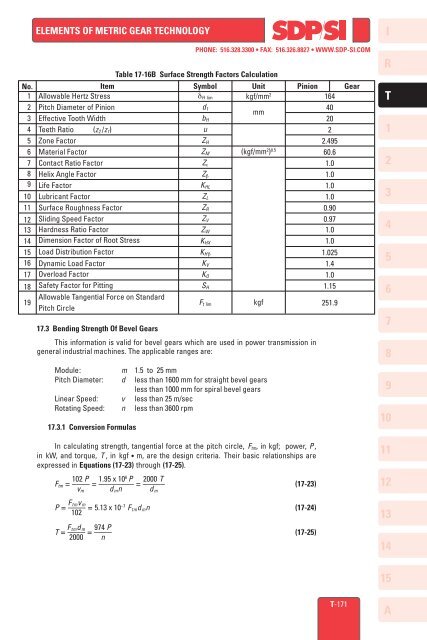
No. Item Symbol Unit Pinion Gear<br />
1 Allowable Hertz Stress<br />
kgf/mm 2<br />
164<br />
2 Pitch Diameter <strong>of</strong> Pinion<br />
40<br />
mm<br />
3 Effective Tooth Width<br />
20<br />
4 Teeth Ratio (z 2 /z 1 )<br />
2<br />
5 Zone Factor<br />
2.495<br />
6 Material Factor<br />
(kgf/mm 2 ) 0.5<br />
60.6<br />
7 Contact Ratio Factor<br />
1.0<br />
8 Helix Angle Factor<br />
1.0<br />
9 Life Factor<br />
1.0<br />
10 Lubricant Factor<br />
1.0<br />
11 Surface Roughness Factor<br />
0.90<br />
Sliding Speed Factor<br />
0.97<br />
Hardness Ratio Factor<br />
1.0<br />
Dimension Factor <strong>of</strong> Root Stress<br />
1.0<br />
12<br />
13<br />
14<br />
15<br />
16<br />
<strong>17</strong><br />
18<br />
19<br />
Load Distribution Factor<br />
Dynamic Load Factor<br />
Overload Factor<br />
Safety Factor for Pitting<br />
Allowable Tangential Force on St<strong>and</strong>ard<br />
Pitch Circle<br />
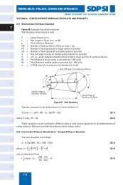
<strong>17</strong>.3 Bending <strong>Strength</strong> Of Bevel <strong>Gears</strong><br />
Table <strong>17</strong>-16B Surface <strong>Strength</strong> Factors Calculation<br />
δ H lim<br />
d 1<br />
b H<br />
u<br />
Z H<br />
Z M<br />
Z ε<br />
Z β<br />
K HL<br />
Z L<br />
Z R<br />
Z V<br />
Z W<br />
K HX<br />
K H β<br />
K V<br />
K O<br />
S H<br />
This information is valid for bevel gears which are used in power transmission in<br />
general industrial machines. The applicable ranges are:<br />
F t lim<br />
Module:<br />
m 1.5 to 25 mm<br />
Pitch Diameter: d less than 1600 mm for straight bevel gears<br />
less than 1000 mm for spiral bevel gears<br />
Linear Speed: v less than 25 m/sec<br />
Rotating Speed: n less than 3600 rpm<br />
<strong>17</strong>.3.1 Conversion Formulas<br />
In calculating strength, tangential force at the pitch circle, F tm , in kgf; power, P ,<br />
in kW, <strong>and</strong> torque, T , in kgf • m, are the design criteria. Their basic relationships are<br />
expressed in Equations (<strong>17</strong>-23) through (<strong>17</strong>-25).<br />
102 P 1.95 x 10 6 P 2000 T<br />
F tm = –––– = –––––––– = ––––– (<strong>17</strong>-23)<br />
v m d m n d m<br />
F tm v m<br />
P = –––– = 5.13 x 10 –7 F tm d m n (<strong>17</strong>-24)<br />
102<br />
F tm d m 974 P<br />
T = –––– = –––– (<strong>17</strong>-25)<br />
2000 n<br />
kgf<br />
1.025<br />
1.4<br />
1.0<br />
1.15<br />
251.9<br />
I<br />
R<br />
T<br />
1<br />
2<br />
3<br />
4<br />
5<br />
6<br />
7<br />
8<br />
9<br />
10<br />
11<br />
12<br />
13<br />
14<br />
15<br />
T-<strong>17</strong>1<br />
A