dtc 1491 (vacuum cut valve bypass valve) diagnosis - Lyberty
dtc 1491 (vacuum cut valve bypass valve) diagnosis - Lyberty
dtc 1491 (vacuum cut valve bypass valve) diagnosis - Lyberty

You also want an ePaper? Increase the reach of your titles
YUMPU automatically turns print PDFs into web optimized ePapers that Google loves.
Classification: Reference: Date<br />
EC02-008 NTB02-033 March 21, 2002<br />
DTC <strong>1491</strong> (VACUUM CUT VALVE BYPASS VALVE) DIAGNOSIS<br />
APPLIED VEHICLE(S):<br />
1998 – 2002 All Models<br />
SERVICE INFORMATION<br />
This bulletin is an aid to the diagnostic procedures in the Service Manual for DTC P<strong>1491</strong>.<br />
If one of the applied vehicles has the MIL “ON” with DTC P<strong>1491</strong> (Vacuum Cut Valve<br />
Bypass Valve) stored in Self-Diagnostic Results, use the service procedure in this bulletin<br />
and the appropriate Service Manual to help you <strong>diagnosis</strong> the incident, if it should occur.<br />
SERVICE PROCEDURE<br />
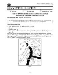
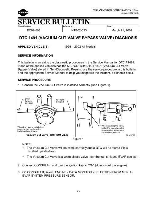
1. Confirm the Vacuum Cut Valve is installed correctly (See Figure 1).<br />
EVAP<br />
Canister<br />
side port<br />
Fuel tank<br />
side port<br />
When the <strong>valve</strong> is installed<br />
correctly, this cap is on the<br />
bottom side as shown.<br />
Vacuum Cut Valve - BOTTOM VIEW<br />
Figure 1<br />
When installing the <strong>valve</strong>,<br />
match the key-way on the<br />
mounting bracket with the<br />
key-way on the <strong>valve</strong>.<br />
NOTE:<br />
• The Vacuum Cut Valve will not work correctly and a DTC will be stored if it is<br />
installed upside-down.<br />
TP020097<br />
• The Vacuum Cut Valve is a white plastic <strong>valve</strong> near the fuel tank and EVAP canister.<br />
2. Connect CONSULT-II and turn the ignition key to “ON” (do not start the engine).<br />
3. On CONSULT II, select ENGINE - DATA MONITOR - SELECTION FROM MENU -<br />
EVAP SYSTEM PRESSURE SENSOR.<br />
1/3
4. Note the EVAP System Pressure Sensor Voltage. Confirm that it is reading in a normal<br />
range for a key ON and engine OFF condition.<br />
NOTE:<br />
For 2001 models and earlier:<br />
• Voltage in step 4 should be near 3.36 volts.<br />
• The normal range is between 3.32 - 3.40 volts.<br />
For 2002 models:<br />
• Some 2002 models use a new type EVAP System Pressure Sensor with different<br />
operational characteristics.<br />
• Refer to the EC section of the appropriate Service Manual to determine which<br />
type sensor your vehicle is equipped with.<br />
• Models that use the new type EVAP System Pressure Sensor will have a voltage<br />
reading that varies with changes in the “barometric” pressure (atmospheric air<br />
pressure that changes with altitude and/or weather conditions).<br />
• The usual voltage range obtained in step 4 with the new type EVAP System<br />
Pressure Sensor is between 3.8 and 4.2 volts. Because this range will vary with<br />
barometric pressure, it is best to compare readings with a known good vehicle.<br />
• Some 2002 models use the earlier type EVAP System Pressure Sensor (same<br />
as used on 2001 and earlier models). The normal range for the earlier type is<br />
3.32 to 3.40 volts and does not vary with barometric pressure.<br />
5. Start the engine. Observe the EVAP System Pressure Sensor voltage.<br />
• If the value has reduced 0.04 volts or more from the reading obtained in step 4,<br />
the EVAP Canister Purge Volume Control Solenoid Valve may be leaking.<br />
• Refer to the EC section of the appropriate Service Manual for inspection<br />
procedures of the EVAP Canister Purge Volume Control Solenoid Valve, DTC<br />
P1444.<br />
NOTE: The EVAP Canister Purge Volume Control Solenoid Valve is located in<br />
the engine compartment.<br />
6. Perform the DTC Confirmation Procedure for DTC P<strong>1491</strong>. Refer to the EC section of<br />
the appropriate Service Manual for confirmation procedure steps and driving conditions.<br />
7. If the DTC confirmation results are NG, do the following:<br />
a. Refer to the EC section of the appropriate Service Manual to determine if the<br />
vehicle is equipped with On-Board Refueling Vapor Recovery (ORVR).<br />
• If the vehicle has ORVR, go to b.<br />
• If the vehicle does NOT have ORVR, go to step 8.<br />
2/3
. Place a clamp on the Refueling EVAP Vapor Line near the fuel tank. The<br />
Refueling EVAP Vapor Line is the larger hose (see figure 2). Use hose clamp<br />
(3M P/N # 08556-1), found in Fuel Injector Cleaning Kit J-45701, or equivalent.<br />
c. Retry DTC Confirmation Procedure<br />
d. If the result is now OK, the Refueling Control Valve may be leaking and should<br />
be inspected. Refer to the EC section of the appropriate Service Manual for<br />
Refueling Control Valve inspection procedures.<br />
8. If the DTC confirmation is still NG after step 7, or the vehicle is not equipped with<br />
ORVR, do the following:<br />
a. Disconnect two (2) lines from the Vacuum Cut Valve. One that goes to the fuel<br />
tank and one that goes to the EVAP Canister (see figure 1).<br />
b. Use a hand <strong>vacuum</strong> pump to check each of the two (2) disconnected hoses for<br />
free flow. Make sure they are clear into the fuel tank (vent line) and into the<br />
EVAP Canister (see figure 2).<br />
NOTE:<br />
Figure 2<br />
• Figure 2 includes ORVR system. Refer to the appropriate service manual to<br />
determine if your vehicle has ORVR or not.<br />
• The lines between the Vacuum Cut Valve and Fuel Tank, and between the<br />
Vacuum Cut Valve and EVAP Canister may go through a metal line. Make<br />
sure the lines are clear between the Vacuum Cut Valve and Fuel Tank, and<br />
between the Vacuum Cut Valve and EVAP Canister, including any metal<br />
lines.<br />
c. If any blockage is found, determine the cause and repair as necessary.<br />
Blockage in either of these lines will cause a DTC.<br />
9. If all of the above checks do not locate the source of the incident, refer to the<br />
appropriate Service Manual for further DTC P<strong>1491</strong> <strong>diagnosis</strong>.<br />
3/3