Sheer Descent Installation Manual - Rick English - Swimming Pool ...
Sheer Descent Installation Manual - Rick English - Swimming Pool ...
Sheer Descent Installation Manual - Rick English - Swimming Pool ...

You also want an ePaper? Increase the reach of your titles
YUMPU automatically turns print PDFs into web optimized ePapers that Google loves.
<strong>Installation</strong> Instructions<br />
Jandy <strong>Sheer</strong> <strong>Descent</strong><br />
<strong>Installation</strong> <strong>Manual</strong><br />
THIS UNIT MUST BE INSTALLED ACCORDING TO THE MANUFACTURER'S INSTALLATION<br />
INSTRUCTIONS. IF QUESTIONS ARISE, PLEASE CALL THE FACTORY AT 800.227.1442 ext 260.<br />
PLEASE READ AND FOLLOW ALL INSTRUCTIONS. PLEASE SAVE THESE INSTRUCTIONS.<br />
PREPARATION AND INSTALLATION INSTRUCTIONS<br />
This manual provides easy reference illustrations to help you identify each part of the <strong>Sheer</strong> <strong>Descent</strong> Waterfall. Use this<br />
manual to guide you through the routine procedures and adjustments for a trouble free installation. These instructions were<br />
developed with the aid of experienced contractors and has proven to be a simple, yet consistent and trouble free, method of<br />
installation.<br />
During all phases of the installation, care should be taken not to damage the <strong>Sheer</strong> <strong>Descent</strong> Waterfall. Keep the unit in the<br />
original packaging until the site is prepared for permanent installation.<br />
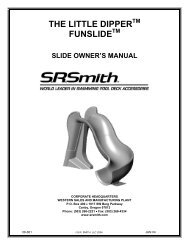
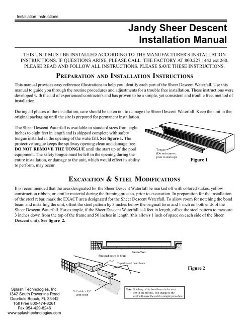
The <strong>Sheer</strong> <strong>Descent</strong> Waterfall is available in standard sizes from eight<br />
inches to eight feet in length and is shipped complete with safety<br />
tongue installed in the opening of the waterfall. See figure 1. The<br />
protective tongue keeps the spillway opening clean and damage free.<br />
DO NOT REMOVE THE TONGUE until the start up of the pool<br />
equipment. The safety tongue must be left in the opening during the<br />
entire installation, or damage to the unit, which would effect its ability<br />
to perform, may occur.<br />
Tongue<br />
(Do not remove<br />
prior to start-up)<br />
Figure 1<br />
EXCAVATION & STEEL MODIFICATIONS<br />
It is recommended that the area designated for the <strong>Sheer</strong> <strong>Descent</strong> Waterfall be marked off with colored stakes, yellow<br />
construction ribbon, or similar material during the framing process, prior to excavation. In preparation for the installation<br />
of the steel rebar, mark the EXACT area designated for the <strong>Sheer</strong> <strong>Descent</strong> Waterfall. To allow room for notching the bond<br />
beam and installing the unit, offset the steel pattern by 3 inches below the original form and 1 inch on both ends of the<br />
<strong>Sheer</strong> <strong>Descent</strong> Waterfall. For example, if the <strong>Sheer</strong> <strong>Descent</strong> Waterfall is 4 feet in length, offset the steel pattern to measure<br />
3 inches down from the top of the frame and 50 inches in length (this allows 1 inch of space on each side of the <strong>Sheer</strong><br />
<strong>Descent</strong> unit). See figure 2.<br />
Steel off set<br />
Finished notch in beam<br />
2½"<br />
Top of raised bond beam<br />
Figure 2<br />
3½" wide x 3½"<br />
deep notch<br />
Note: Notching of the bond beam is the next<br />
step in the process. The change to the<br />
steel will make the notch a simple procedure.<br />
1
CONCRETE INSTALLATION AND MODIFICATIONS<br />
As the concrete installation (or similar process) nears completion, a notch must be cut into the inner edge of bond beam in<br />
the same area at which the steel was offset to allow for the installation of the <strong>Sheer</strong> <strong>Descent</strong> Waterfall. See figure 3.<br />
CUTTING THE BOND BEAM<br />
FOR SHEER DESCENT WATERFALL SIZES 8" THROUGH 5'<br />
Select the EXACT location for the <strong>Sheer</strong> <strong>Descent</strong> Waterfall.<br />
The notch in the bond beam should be cut 3½" deep by<br />
2½" wide and 2" longer than the length of the proposed<br />
<strong>Sheer</strong> <strong>Descent</strong> Waterfall (1" per side). For example, if a<br />
4' model is to be installed, the notch length should be 50"<br />
(48" + 1"+ 1" = 50"). In addition, mark a single slot on<br />
the top of the beam in the center of the proposed notch<br />
3½" wide by 3½" deep. The notch will be used to plumb<br />
1½" pipe to the <strong>Sheer</strong> <strong>Descent</strong> Waterfall. Mark the bond<br />
beam and proceed with cutting the beam.<br />
FOR SHEER DESCENT SIZES 6', 7', AND 8'<br />
Tile<br />
Tongue<br />
3½" wide x 3½" deep notch<br />
2½"<br />
3½"<br />
Figure 3<br />
Mark and cut the beam as instructed previously, with the exception that two notches are required on the top of the beam<br />
for piping. Longer waterfalls require more water; consequently, two plumbing lines are required. The top of the beam<br />
should be marked for these units as follows: NOTE: These measurements are from the center of the <strong>Sheer</strong> <strong>Descent</strong><br />
Waterfall unit.<br />
Length<br />
Plumbing Location<br />
6 foot 1 foot 6 inches to the right and to the left from the center line<br />
7 foot 1 foot 9 inches to the right and to the left from the center line<br />
8 foot 2 feet to the right and to the left from the center line<br />
The notches should be 3½" wide by 3½" deep. See figure 4.<br />
Manifold<br />
Rock trap<br />
MAKE SURE THE CUTS IN THE BEAM ARE PROPERLY COMPLETED BEFORE PROCEEDING.<br />
Beam<br />
Center<br />
<strong>Sheer</strong> <strong>Descent</strong> Waterfall back feed<br />
plumbing for 6, 7, & 8 ft. lengths.<br />
Figure 4<br />
PUMP SIZING AND INSTALLATION OPTIONS<br />
One of the advantages of the <strong>Sheer</strong> <strong>Descent</strong> Waterfall is the ability to provide a continuous sheet of water with a minimum<br />
of water flow. A standard four foot model, for example, requires only 40 gallons per minute to operate. In order to size<br />
your pump properly, refer to the Water Flow Requirement Chart. In most<br />
Feet of Projection<br />
cases, a properly sized standard swimming pool pump will operate the <strong>Sheer</strong><br />
1 2<br />
<strong>Descent</strong> Waterfall and filter the pool with little loss of total water turnover. As 3<br />
a general rule of thumb, the <strong>Sheer</strong> <strong>Descent</strong> waterfall requires approximately<br />
10 gallons per minute per foot with little head loss. For more a dramatic effect,<br />
more water gallonage can be applied to project the waterfall further away from<br />
the wall. NOTE: When plumbing multiple falls, add the total length of<br />
2<br />
waterfalls together to determine GPM required. e.g. When plumbing two<br />
(2) 6' units, you now have 12' of waterfall, which requires 120 gallons per<br />
minute.<br />
1<br />
EXISTING POOL FILTER PUMP INSTALLATION<br />
The installation of the <strong>Sheer</strong> <strong>Descent</strong> Waterfall using the main pool filter pump<br />
is the most common plumbing system, due to the unique low flow aspect of the<br />
waterfall system. Simply plumb a three way valve on the return line, after the<br />
7 9 1012 15 20<br />
filter, and plumb the waterfall feed line in a minimum of 1½" PVC schedule<br />
Gallons per minute per foot<br />
40 pipe. Units above 5' in length need a minimum of 2" plumbing.<br />
Guideline is for 1ft. to 4ft models<br />
2<br />
Feet of Elevation
SEPARATE PUMP FOR THE SHEER DESCENT WATERFALL<br />
If multiple waterfalls are being installed, or a <strong>Sheer</strong><br />
<strong>Descent</strong> Waterfall 6' or longer is being installed, we Cantilever edge<br />
recommend installing a separate pump. When<br />
plumbing a pump dedicated for use by the <strong>Sheer</strong> <strong>Sheer</strong> <strong>Descent</strong> unit<br />
<strong>Descent</strong>, a separate suction line to the pool must be<br />
Tile<br />
plumbed. This should be plumbed in a minimum of<br />
Water line<br />
2" schedule 40 pipe.<br />
NOTE: At least one anti-vortex safety suction<br />
cover must be installed at pool side as a safety<br />
precaution. The anti-vortex suction cover is<br />
recommended to be positioned 18 inches above<br />
the floor of the pool.<br />
Anti vortex<br />
cover<br />
Conventional<br />
concrete decking<br />
Suction line<br />
Rock trap<br />
Separate return<br />
to pool<br />
Jandy three<br />
way valve<br />
Next, a <strong>Sheer</strong> <strong>Descent</strong> filter/strainer (part #3456),<br />
or equivalent, must be installed on the return side<br />
of the pump, between the pump and the <strong>Sheer</strong><br />
<strong>Descent</strong> Waterfall. A FILTER IS REQUIRED<br />
for separate pump installations, as large debris<br />
must not be allowed to enter the <strong>Sheer</strong> <strong>Descent</strong><br />
Figure 5<br />
<strong>Sheer</strong> <strong>Descent</strong><br />
filter/strainer<br />
unit. For installations requiring up to 60 gallons per minute, use one <strong>Sheer</strong> <strong>Descent</strong> filter. For higher water requirements,<br />
use two or more filters plumbed in parallel. A separate return line, with a three way valve plumbed in such a way that<br />
water can be balanced between the <strong>Sheer</strong> <strong>Descent</strong> Waterfall and return back to the pool, is also required. See figure 5.<br />
Filter<br />
pump<br />
WATERFALL RETURN LINE PLUMBING<br />
PLUMBING THE SHEER DESCENT WATERFALL<br />
The waterfall feed line, from either the main filter pump or a separate pump, should be plumbed in a minimum of 1½"<br />
PVC pipe. NOTE: Two inch plumbing or larger is suggested for waterfalls over 5 feet in total length. Refer to<br />
Hydraulic Guideline Chart for specifications. The feed line should end near the back of the bond beam near the center of<br />
the waterfall location.<br />
It is important to have a valve located in a convenient location on the feed line to regulate the flow of water to the <strong>Sheer</strong><br />
<strong>Descent</strong> Waterfall. A Jandy three-way valve is suggested to be<br />
used as the "T" from the return line of the pool to the <strong>Sheer</strong><br />
<strong>Descent</strong> Waterfall. A properly plumbed valve in that position<br />
will allow full control of the water to the <strong>Sheer</strong> <strong>Descent</strong>, as well<br />
as to the rest of the pool. In most cases, this valve can be<br />
located after the filter near the equipment pad. See figure 6.<br />
NOTE: All water to the <strong>Sheer</strong> <strong>Descent</strong> must be filtered.<br />
Those systems using a separate pump must use our separate<br />
filter (part #3456) to prevent debris from entering the <strong>Sheer</strong><br />
<strong>Descent</strong> unit.<br />
Figure 6<br />
Rock trap<br />
Water to<br />
sheer descent<br />
Return to pool<br />
Filter<br />
Jandy three<br />
way valve<br />
Pump<br />
Suction<br />
from pool<br />
3<br />
H YDRAULIC GUIDELINE CHART<br />
•Use minimum of 1½" pipe.<br />
•Use minimum of 2" pipe for runs in excess of 60<br />
feet or if <strong>Sheer</strong> <strong>Descent</strong> unit is over 5 feet.<br />
•Dedicated plumbing lines are recommended.<br />
•Maximum recommended flow for a typical installation:<br />
1½" pipe for 60 GPM<br />
2" pipe for 100 GPM<br />
2½" pipe for 140 GPM<br />
3" pipe for 225 GPM<br />
Typical pump performance at 50 Feet of head<br />
½ HP = 26 GPM<br />
¾ HP = 58 GPM<br />
1 HP = 68 GPM<br />
1½ HP = 93 GPM<br />
2 HP = 106 GPM<br />
3 HP = 140 GPM
PLUMBING A SINGLE UNIT<br />
All Backfeed <strong>Sheer</strong> <strong>Descent</strong> Waterfalls have the equivalent of standard 1½ inch pipe protruding from the back of the unit.<br />
For waterfalls eight inches through five feet in length, this fitting is located in the center of the back of the waterfall.<br />
For <strong>Sheer</strong> <strong>Descent</strong> waterfalls 6, 7, and 8 feet in length, two 1½ inch fittings are located as follows:<br />
<strong>Sheer</strong> <strong>Descent</strong> Length<br />
Plumbing Location<br />
6 foot 1 foot, 6 inches to the right and to the left from the center line<br />
7 foot 1 foot, 9 inches to the right and to the left from the center line<br />
8 foot 2 feet to the right and to the left from the center line<br />
NOTE: A plumbing manifold is included with all <strong>Sheer</strong> <strong>Descent</strong> Waterfalls 6, 7, and 8 feet in length, to assist in<br />
proper plumbing. Simply plumb the manifold to the waterfall, install the Rock Trap and the plumbing is complete!<br />
Standard 1½" PVC fittings will glue over the 1½" pipe provided on all <strong>Sheer</strong> <strong>Descent</strong> Waterfalls. Make sure the fittings<br />
are properly glued. Also, make sure the Rock Trap is properly installed as close to the waterfall as possible (figure 6).<br />
See page 5 for Rock Trap installation instructions.<br />
NOTE: A flow control valve must be plumbed in a convenient location on the supply line for regulation of the water<br />
supply to the unit. See figure 7.<br />
Ensure plumbing lines to unit are clear of debris.<br />
Ensure plumbing is properly sized<br />
Figure 7<br />
Rock Trap<br />
Rock Trap<br />
Manifold<br />
Notch in beam<br />
Beam<br />
Beam<br />
Back Feed plumbing<br />
for units 8"through 5'<br />
Back Feed plumbing<br />
for units 6', 7', & 8'<br />
PLUMBING MULTIPLE UNITS<br />
Plumbing two or more <strong>Sheer</strong> <strong>Descent</strong> Waterfalls together is done in exactly the same way as the installation procedure for a<br />
single unit, explained previously, with the exception that additional two-way valves are required for each <strong>Sheer</strong> <strong>Descent</strong><br />
Waterfall. These valves regulate and balance the amount of water between the various waterfalls. For units 6', 7' and 8'<br />
long, separate minimum 2" lines are required, with valves to regulate the balance. See to figure 8.<br />
Make sure no debris is in any of the plumbing lines in the unit<br />
Rock trap<br />
Jandy<br />
Valve<br />
Rock trap<br />
Figure 8<br />
Jandy<br />
Valve<br />
<strong>Sheer</strong> <strong>Descent</strong> Waterfall<br />
back feed plumbing for<br />
eight inch through five feet<br />
<strong>Sheer</strong> <strong>Descent</strong> Waterfall<br />
back feed plumbing for<br />
six, seven and eight feet<br />
4
INSTALLING THE SHEER DESCENT WATERFALL<br />
The <strong>Sheer</strong> <strong>Descent</strong> Waterfall is generally installed by the tile installer. NOTE: The <strong>Sheer</strong> <strong>Descent</strong> Waterfall must be<br />
installed prior to installing the decks and coping. Place the <strong>Sheer</strong> <strong>Descent</strong> Waterfall in the pre-cut notch in the bond<br />
beam. Level the top of the <strong>Sheer</strong> <strong>Descent</strong> unit to the upper edge of the<br />
bond beam with tile shims.<br />
NOTE: The top of the <strong>Sheer</strong> <strong>Descent</strong> is where the opening and<br />
tongue are located. Fill the gaps around the unit with concrete<br />
brown coat, or similar material, and surface the face of the <strong>Sheer</strong><br />
<strong>Descent</strong> unit in preparation for tile. The face of the <strong>Sheer</strong> <strong>Descent</strong> has<br />
been designed to allow concrete to "grip" the surface and assure a strong<br />
tile bond. Cut the tile to fit under the "lip" of the unit and secure with<br />
"thin set" or similar compound. See figure 9.<br />
Figure 9<br />
Spillway<br />
Spillway must be<br />
flush with tile or<br />
overhang by 1/8"<br />
Water line<br />
Tile<br />
<strong>Sheer</strong> <strong>Descent</strong> Waterfall<br />
(side view)<br />
Undercoat or browncoat<br />
then thin set and tile<br />
START UP INSTRUCTIONS<br />
After the swimming pool is completed and filled with water, the <strong>Sheer</strong> <strong>Descent</strong> Waterfall is ready to be activated.<br />
REMOVE THE TONGUE NOW. This must be done before water is diverted to the waterfall. Also, ensure the opening<br />
is clean and clear of any debris. Turn the pump on. If the waterfall is plumbed with the main pool filter pump, allow the<br />
pump to run a few minutes to clear the lines of debris. Slowly open the regulating valve and supply water to the <strong>Sheer</strong><br />
<strong>Descent</strong> Unit. Adjust the flow of water until the sheet of water extends out onto the pool surface. Allow for air to clear the<br />
lines. This should only take a few minutes. The <strong>Sheer</strong> <strong>Descent</strong> Waterfall unit should now provide a clear, continuous sheet<br />
of water.<br />
In the event a separate pump was installed, make sure all valves are open prior to starting the pump. ENSURE ALL<br />
LINES ARE CLEAR OF DEBRIS BEFORE STARTING. Start the pump and allow water to circulate through the<br />
separate filter system and return line. Slowly open the valve to the waterfall and regulate to the desired setting. Allow a<br />
few minutes to purge all air from the lines.<br />
FREEZE PROTECTION AND WINTERIZATION<br />
In order to prevent freeze damage to the system, the plumbing to the unit must be installed so water drains easily from the<br />
system. The <strong>Sheer</strong> <strong>Descent</strong> Waterfall has been engineered to allow only a minimum of water to stay in the unit as long as<br />
the plumbing is installed properly. For winterizing, blow all lines and follow normal procedure.<br />
ROCK TRAP INSTALLATION INSTRUCTIONS (Rock Trap optional on some models)<br />
¨<br />
Install the Rock Trap as close to the water fixture (waterfall, jets, etc.) as<br />
possible, to assure maximum protection.<br />
Screen<br />
¨<br />
¨<br />
Rock Trap must be installed with debris collection chamber pointed DOWN.<br />
See figure 10.<br />
Prior to gluing the Rock Trap, ensure flow arrow is properly aligned.<br />
From pump<br />
To sheer<br />
descent<br />
¨<br />
NEVER install Rock Trap where debris chamber cannot be pointed DOWN.<br />
Right<br />
Rock trap<br />
Wrong<br />
Debris<br />
trap<br />
ROCK TRAP<br />
INSTALLATION<br />
OPTIONS<br />
Figure 10<br />
5
SHEER DESCENT EXTENDED LIP WATERFALL<br />
The <strong>Sheer</strong> <strong>Descent</strong> Extended Lip Waterfall is used for radius cuts or when the lip of the waterfall needs to extend over<br />
wide objects such as brick, glass block, etc. The lip extension is 6" (the standard <strong>Sheer</strong> <strong>Descent</strong> Waterfall has a one inch<br />
lip). Operation and installation of both products is identical, with the exception that the steel pattern and notch in the beam<br />
may need to be altered to accommodate the lip width. NOTE: The extended lip must be fully supported. See figure 11.<br />
Mortar will not stick to the plastic parts on the <strong>Sheer</strong> <strong>Descent</strong> Waterfall. When using various types of coping material,<br />
consult with your decking contractor for appropriate installation and or modification to the installation.<br />
<strong>Sheer</strong> <strong>Descent</strong> Extended Lip Waterfall<br />
Figure 11<br />
Brick<br />
Tongue<br />
NOTE: The tongue must stay in place during entire<br />
installation, but make sure it is removed prior to system start<br />
up. All aspects of the installation are the same as the<br />
standard model <strong>Sheer</strong> <strong>Descent</strong> Waterfall.<br />
Brick<br />
Bond beam<br />
Rock Trap<br />
Tile<br />
Bond beam<br />
Notch back<br />
of beam<br />
Brick<br />
Over Brick/Rock <strong>Installation</strong><br />
Over the Beam <strong>Installation</strong><br />
CUTTING THE LIP FOR CURVES OR CUSTOM INSTALLATIONS<br />
The extended lip <strong>Sheer</strong> <strong>Descent</strong> Waterfall can be custom cut in the field to meet specific needs, such as curves, irregular<br />
shapes, etc. In order to custom fit the waterfall, carefully measure the amount of extended lip to be removed. Remember to<br />
leave enough room for tile and thin set, so the deepest edge of the radius cut will not be recessed from the tile line. NOTE:<br />
Never remove more than 4½" of the extended lip, leaving a minimum of 1½" of lip. See figure 12. Remove the<br />
protective tongue prior to cutting the waterfall. Remember to REPLACE THE TONGUE after cutting the radius to<br />
protect the fall from construction debris. An additional tongue is provided in product packaging.<br />
The waterfall must be cut with a coarse tooth saw blade. Running water can be applied to the surface being cut to keep the<br />
blade cool. Caution must be taken to make the cut as smooth as possible to avoid a jagged edge. After cutting the<br />
waterfall, insert the support removal tool (included in product packaging) 1 inch into the waterfall opening. Move the tool<br />
around the opening. If the tool hits a support, use the notch in the tool to remove the support. See figure 13a. Make sure<br />
all supports within 1 inch of lip opening are removed. See figure 13b. DO NOT LEAVE THE LOOSE SUPPORT<br />
SECTION IN THE WATERFALL.<br />
After removing sections of the supports, use a coarse grade of sandpaper to smooth the edges of the waterfall, follow with<br />
a fine grade of sandpaper to get the edge as smooth as possible. A sanding block is recommended to avoid rounding the<br />
edges of the waterfall.<br />
Insert the tongue back into the opening and continue installation, following the installation instructions for the standard<br />
<strong>Sheer</strong> <strong>Descent</strong> Waterfall. NOTE: Two tongues are provided with every extended lip waterfall. Use the appropriate<br />
tongue to fully cover the opening. The long tongue can be "V" cut, as shown in figure 13b, to allow for curved<br />
installations. The smaller piece of tongue, which is provided in the packaging, is used to make up any sizing<br />
difference due to the radius cut. When installing the smaller piece, make sure the fit is tight and no debris can enter<br />
the spillway opening.<br />
Convex Curve<br />
Convex Curve<br />
1½" minimum<br />
Concave Curve<br />
Concave Curve with Tongue<br />
¼"<br />
½"<br />
Break off lip supports<br />
1" from lip of waterfall Support<br />
removal tool<br />
Insert Tongue Assemble<br />
Break off lip supports<br />
1" from lip of waterfall<br />
Support<br />
removal tool<br />
Insert Tongue Assemble<br />
Figure 12 Figure 13a Figure 13b<br />
6<br />
6"<br />
¾"
SHEER DESCENT WATERFALL RADIUS CUT GUIDELINE<br />
NOTE: Never remove more than 4½" of the extended lip, leaving a minimum of<br />
1½" of lip. The top of the beam, where the <strong>Sheer</strong> <strong>Descent</strong> unit is to be installed,<br />
should be a minimum of 9" thick. When designing custom curves for the <strong>Sheer</strong><br />
<strong>Descent</strong> Extended Lip models, please refer to the following Minimum Radius Guidelines<br />
Table to select the correct <strong>Sheer</strong> <strong>Descent</strong> model. Super Radius models accommodate<br />
very tight radius curves and are available by special order.<br />
<strong>Sheer</strong> <strong>Descent</strong> Waterfall<br />
extended lip radius installation<br />
Do not<br />
remove more<br />
than 4½"<br />
MINIMUM RADIUS GUIDELINES TABLE KEY<br />
<strong>Sheer</strong> <strong>Descent</strong> Model Abbreviation Customize Cut<br />
Extended Lip EL Field Cut or Factory Cut<br />
Super Radius SR FACTORY CUT ONLY<br />
SHEER DESCENT WATERFALL LENGTH<br />
1' 1.5' 2' 3' 4' 5' 6' 7' 8'<br />
Radius<br />
1' EL - - - - - - - -<br />
1.5' EL EL - - - - - - -<br />
2" EL EL EL SR<br />
2.5' EL EL EL SR - - - - -<br />
3' EL EL EL SR SR - - - -<br />
3.5' EL EL EL SR SR - - - -<br />
4' EL EL EL EL SR - - - -<br />
4.5' EL EL EL EL SR SR - - -<br />
5' EL EL EL EL SR SR - - -<br />
5.5' EL EL EL EL SR SR - - -<br />
6' EL EL EL EL EL SR SR - -<br />
6.5' EL EL EL EL EL SR SR - -<br />
7' EL EL EL EL EL SR SR - -<br />
7.5' EL EL EL EL EL SR SR - -<br />
8' EL EL EL EL EL SR SR - -<br />
8.5' EL EL EL EL EL SR SR SR -<br />
9' EL EL EL EL EL SR SR SR -<br />
9.5' EL EL EL EL EL EL SR SR -<br />
10' EL EL EL EL EL EL SR SR -<br />
10.5' EL EL EL EL EL EL SR SR -<br />
11' EL EL EL EL EL EL SR SR -<br />
12' EL EL EL EL EL EL SR SR -<br />
12.5' EL EL EL EL EL EL EL SR SR<br />
13' EL EL EL EL EL EL EL SR SR<br />
TROUBLE SHOOTING GUIDE<br />
Before proceeding, make sure the pump system is fully functional and activated. Also, ensure all air is purged from<br />
plumbing lines.<br />
Problem à<br />
The <strong>Sheer</strong> <strong>Descent</strong> Waterfall is not<br />
completely smooth. A gap in the sheet<br />
of the water is present.<br />
Problem à<br />
Where multiple <strong>Sheer</strong> <strong>Descent</strong><br />
Waterfalls are installed, one of the<br />
waterfalls is stronger than the other.<br />
Cause à<br />
Debris in the plumbing has lodged in<br />
the opening of the waterfall.<br />
Cause à<br />
The water supplied to the units is not<br />
properly balanced.<br />
7<br />
Solution<br />
Use a credit card or similar object and<br />
gently position it inside the opening<br />
while the waterfall is on. Slide it<br />
along the opening to the point where<br />
the debris is located and gently pull<br />
the debris through the opening.<br />
Solution<br />
Adjust the valves for each waterfall<br />
until the proper effect and balance is<br />
achieved. See figure 8 for valve<br />
location.