
Create successful ePaper yourself
Turn your PDF publications into a flip-book with our unique Google optimized e-Paper software.
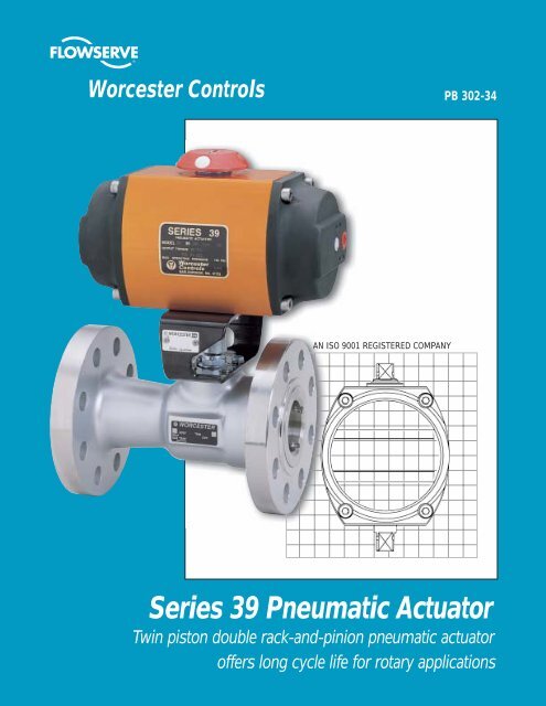
<strong>Worcester</strong> Controls<br />
PB 302-34<br />
AN ISO 9001 REGISTERED COMPANY<br />
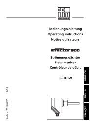
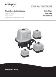
<strong>Series</strong> <strong>39</strong> Pneumatic Actuator<br />
Twin piston double rack-and-pinion pneumatic actuator<br />
offers long cycle life for rotary applications
Flow Control Division<br />
<strong>Worcester</strong> Controls<br />
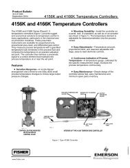
<strong>Series</strong> <strong>39</strong> Pneumatic Actuators<br />
High cycle pneumatic power for on-off or throttling<br />
control of rotary valves and dampers<br />
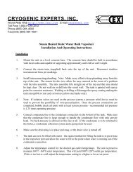
One-piece steel pinion drive<br />
with full length, nickel coated<br />
rack/pinion tooth engagement for<br />
greater operational life<br />
Stainless steel fasteners<br />
improve aesthetics and ease<br />
of maintenance<br />
Namur (VDI/VDE) top mounting<br />
for easy fitting and<br />
interchangeability of switches,<br />
positioners, etc.<br />
Position indicator<br />
provides external indication<br />
of valve position<br />
Coro-lube coated aluminum<br />
construction for corrosion<br />
resistance and superior wear<br />
performance on internal and<br />
external surfaces<br />
Corrosion<br />
protected springs<br />
for long service life<br />
*Polished<br />
stainless steel<br />
piston guide rods<br />
minimize internal<br />
wear and maximize<br />
performance life<br />
Balanced double<br />
rack-and-pinion<br />
eliminates side loads<br />
ISO 5211 mounting pattern<br />
for interchangeability of mounting<br />
kits and greater mechanical strength<br />
Multi-spring concept<br />
provides variable torque/air<br />
pressure performance from<br />
the same actuator<br />
Unique unrestricted air<br />
flow through guide rods<br />
gives fast operation<br />
speeds as standard<br />
Long screws<br />
to allow complete release<br />
of spring energy for safe<br />
disassembly when required<br />
* Size 05<strong>39</strong> does not utilize piston guide rods.<br />
Features and Benefits<br />
■<br />
Available as spring return<br />
or double acting<br />
■<br />
All parts sealed and greased for<br />
life, no maintenance required<br />
■<br />
Can be mounted for fail-open<br />
or fail-closed operation<br />
■<br />
Large range of sizes for<br />
efficient torque matching<br />
■<br />
Safe disassembly, no<br />
special tools required<br />
■<br />
Backed by our exclusive<br />
two-year warranty<br />
2
Flow Control Division<br />
<strong>Worcester</strong> Controls<br />
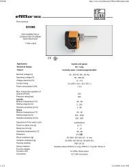
Operating Principle<br />
DOUBLE ACTING ACTUATOR <strong>39</strong><br />
TOP VIEW<br />
PORT 1<br />
AIR SUPPLY<br />
PORT 2<br />
VENT OUT<br />
STROKE OPENING<br />
TOP VIEW<br />
PORT 1<br />
AIR EXHAUST<br />
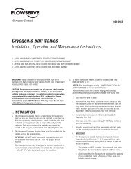
The <strong>Series</strong> <strong>39</strong> Pneumatic Actuator design is based<br />
on the opposed rack-and-pinion principle utilizing<br />
piston guide rods to guarantee part alignment. The<br />
fully supported guide rods minimize friction and<br />
wear between the pistons and the body bore.<br />
In the double acting actuator, compressed air is<br />
applied to Port 1. The air flows through the rear<br />
guide rod, enters the center chamber to push the<br />
pistons apart, turning the shaft counter-clockwise<br />
(as seen from above) to open the valve. During this<br />
action, air in the end caps is vented through Port 2<br />
via the front guide rod. Action is reversed, i.e. the<br />
valve is closed, by applying air to Port 2 and venting<br />
air through Port 1.<br />
In a fail-safe spring return actuator, springs are<br />
nested in the end caps. The number of springs in<br />
each cap depends on the available supply air<br />
pressure and required torque output. Air is supplied<br />
through Port 1 to the center chamber to push the<br />
pistons apart which compresses the springs. During<br />
this action, air in the end caps is vented through Port<br />
2 via the front guide rod. When air is vented out<br />
through Port 1 (via a three-way solenoid valve) the<br />
springs push the pistons back together thus closing<br />
the valve. Port 2 is continuously vented. The springs<br />
provide a dependable, safe closure in the event of<br />
electrical or air supply failure.<br />
STROKE CLOSING<br />
SPRING RETURN ACTUATOR <strong>39</strong>S<br />
TOP VIEW<br />
STROKE OPENING<br />
TOP VIEW<br />
PORT 2<br />
VENT IN<br />
PORT 1<br />
AIR SUPPLY<br />
PORT 2<br />
VENT OUT<br />
PORT 1<br />
AIR EXHAUST<br />
PORT 2<br />
VENT IN<br />
STROKE CLOSING<br />
3
Flow Control Division<br />
<strong>Worcester</strong> Controls<br />
Product Specifications<br />
• Pneumatic Actuators shall be of a dualpiston<br />
design for compactness, highest<br />
torque output, minimal air consumption and<br />
even weight distribution (balanced) on the<br />
valve stem.<br />
• Actuators shall be equipped with two piston<br />
guide rods to bear the lateral rack-andpinion<br />
thrust forces, increasing piston seal<br />
life and eliminating the possibility of cylinder<br />
scratching by the pistons. Elastomeric seals<br />
shall not be loaded as bearings.<br />
• The torque shall be generated through a<br />
double rack-and-pinion gearing mechanism<br />
with full-length, uninterrupted engagement<br />
of the rack-and-pinion teeth.<br />
• The rack shall be machined as part of the<br />
piston in order to extend the actuator life<br />
and eliminate hysteresis.<br />
• Actuator housings shall be protected both<br />
internally and externally with a nickel acetate<br />
filled coating for corrosion resistance.<br />
• Single acting actuators shall use multisprings<br />
at each end to eliminate uneven<br />
forces on the pistons and shall be field<br />
adaptable to reduced pressure air supplies.<br />
• Actuators shall have external extended<br />
shafts for position indication and manual<br />
override capability.<br />
• Actuators shall have optional integral endmounted<br />
limit switches, reducing overall<br />
height and allowing the use of extended<br />
actuator shafts as manual override.<br />
• Actuators shall have optional integral<br />
solenoid valving without the use of transfer<br />
tubes. Valving shall incorporate fail-safe<br />
action upon interruption of electrical signal.<br />
• Actuator manufacturer shall offer the<br />
minimum of a two-year warranty.<br />
As manufactured and offered by Flowserve.<br />
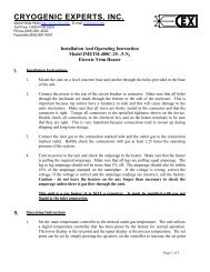
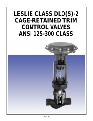
Parts List/Material Specifications<br />
1<br />
2<br />
10<br />
3<br />
6<br />
4<br />
7<br />
5<br />
8<br />
9<br />
4<br />
ITEM NO. DESCRIPTION MATERIAL/FINISH<br />
1 Body Aluminum (Extrusion) Anodized<br />
2 Pinion Carbon Steel (Corrosion Resistant Coated)<br />
3 Pistons Aluminum<br />
4 End Caps Aluminum Anodized<br />
5 Guide Rods Stainless Steel<br />
6 Bearings Acetal<br />
7 “O” Rings Nitrile Rubber<br />
8 End Cap Screws Stainless Steel<br />
9 Springs Chrome Silicon (Corrosion Resistant Coated)<br />
10 Position Indicator Polyethylene
Flow Control Division<br />
<strong>Worcester</strong> Controls<br />
Solenoid Mounting<br />
SOLENOID BLOCK - DIRECT MOUNTED<br />
The solenoid end cap of each actuator is pre-drilled to allow rapid<br />
attachment of either a double acting or spring return solenoid<br />
control block.<br />
The double acting solenoid control block provides extremely fine and<br />
independent adjustments for speed control on the opening and closing<br />
strokes of a double acting actuator (20:1 ratio). The double acting<br />
solenoid control block can be overridden by manual operation of the<br />
control block spool.<br />
The spring return solenoid control block provides an optional adjustment<br />
for speed control on the spring stroke of a spring return actuator.<br />
Both double acting and spring return styles will return to the<br />
actuator “closed” position (pistons together) upon electrical failure.<br />
General Purpose TYPE1<br />
Solenoid Coil Data<br />
(Class A Coil)<br />
VOLTAGE INRUSH AMPS HOLDING AMPS<br />
24 VAC 50/60 HZ 1.20 .80<br />
120 VAC 50/60 HZ .30 .15<br />
240 VAC 50/60 HZ .12 .08<br />
12 VDC — .70<br />
24 VDC — .35<br />
Watertight/Hazardous Locations TYPE<br />
4, 4x, 7 & 9 Solenoid Coil Data<br />
(Class F Coil)<br />
VOLTAGE INRUSH AMPS HOLDING AMPS<br />
24 VAC 50/60 Hz 1.13 .71<br />
120 VAC 50/60 Hz .23 .14<br />
240 VAC 50/60 Hz .11 .07<br />
12 VDC — .81<br />
24 VDC — .41<br />
Solenoids are available<br />
in the following types:<br />
General Purpose TYPE 1;<br />
Watertight TYPE 4, 4x;<br />
Hazardous Locations<br />
TYPE 7 (UL & CSA listed<br />
for Class I, Division I,<br />
Groups A, B, C & D) and<br />
TYPE 9 (UL & CSA listed<br />
for Class II, Groups E, F<br />
& G). The Type 7<br />
solenoid is also rated<br />
Type 4, 4x.<br />
Four-Way Double Acting Solenoid<br />
Speed Control<br />
Screws<br />
(Standard)<br />
Three-Way Spring Return Solenoid<br />
Speed<br />
Control Nut<br />
(Standard)<br />
Manual<br />
Override<br />
Namur Solenoid Interface<br />
Optional Namur VDI/VDE 3845 interface end caps<br />
and direct mount Namur solenoids are available<br />
making the <strong>Series</strong> <strong>39</strong> a truly international<br />
actuator. All ports are G 1/4 except size 05 and<br />
10, which are G 1/8. Consult table on back cover<br />
for ordering details.<br />
Three-way Namur solenoids include a standard<br />
rebreather feature.<br />
Namur End Cap<br />
(designated V64)<br />
Namur<br />
Mounted Solenoid<br />
5
Flow Control Division<br />
<strong>Worcester</strong> Controls<br />
Torque Output<br />
Sizing<br />
Determine appropriate valve torque<br />
requirements from valve literature. For double<br />
acting actuators, select the actuator whose<br />
torque output at available air supply exceeds<br />
breakaway torque requirements of the valve.<br />
For detailed instructions, consult <strong>Worcester</strong><br />
Controls’ Ball Valve Actuator Selection<br />
Manual, brochure V400.<br />
For fail-closed, spring return actuators, select<br />
the appropriate size actuator whose torque<br />
output at end of the spring stroke (at available<br />
air supply) is sufficient to close the valve.<br />
For fail-open spring return actuators, select<br />
appropriate actuator whose torque output at<br />
the end of the air stroke is sufficient to close<br />
the valve. For fail-open actuators, it is also<br />
necessary to determine that the torque output<br />
at the start of the spring stroke exceeds<br />
breakaway requirements of the valve.<br />
Double Acting Actuator<br />
33<strong>39</strong><br />
35<strong>39</strong><br />
40<strong>39</strong><br />
42<strong>39</strong><br />
Spring Return Actuator<br />
Operating Pressure<br />
30 (2.0) 40 (2.7) 50 (3.4) 60 (4.1) 70 (4.8) 80 (5.4)<br />
No. of Springs 2<br />
4<br />
6<br />
8<br />
8 10<br />
Model<br />
No.<br />
10<strong>39</strong><br />
15<strong>39</strong><br />
20<strong>39</strong><br />
25<strong>39</strong><br />
30<strong>39</strong><br />
Stroke Start End Start End Start End Start End Start End Start End<br />
Air 70 40 85 60 105 60 125 70 170 120 175 95 in-lb<br />
7.9 4.5 9.6 6.8 11.9 6.8 14.1 7.9 19.2 13.6 19.8 10.7 N m<br />
Spring 58 35 60 35 95 55 125 75 125 75 160 95 in-lb<br />
6.6 4.0 6.8 4.0 10.7 6.2 14.1 8.5 14.1 8.5 18.1 10.7 N m<br />
Air 140 60 130 85 200 125 240 150 260 155 325 190 in-lb<br />
15.8 6.8 14.7 9.6 22.6 14.1 27.1 16.9 24.9 16.4 31.6 20.9 N m<br />
Spring 100 60 105 74 165 105 220 145 220 145 280 185 in-lb<br />
11.3 6.8 11.9 7.3 18.6 11.9 24.9 16.4 24.9 16.4 31.6 20.9 N m<br />
Air 220 150 300 240 340 235 415 280 575 440 600 360 in-lb<br />
24.9 17.0 33.9 27.1 38.4 26.6 46.9 31.6 65 49.7 67.8 40.7 N m<br />
Spring 140 95 190 125 300 195 400 265 400 265 505 335 in-lb<br />
15.8 10.7 21.5 14.1 33.9 22.0 45.2 29.9 45.2 29.9 57.0 37.9 N m<br />
Air 220 110 560 400 600 350 730 420 925 655 980 550 in-lb<br />
24.9 12.4 63.3 45.2 67.8 <strong>39</strong>.5 82.5 47.5 105 74 111 62.1 N m<br />
Spring 240 170 345 210 540 330 720 450 720 450 915 575 in-lb<br />
27.1 19.2 <strong>39</strong>.0 23.7 61.0 37.3 81.4 50.8 81.4 50.8 103 65.0 N m<br />
Air 324 180 840 610 965 600 1130 690 1575 1145 1650 920 in-lb<br />
36.6 20.3 94.9 68.9 108 67.8 128 78.0 178 129 186 104 N m<br />
Spring 456 264 560 340 870 535 1160 730 1160 730 1470 920 in-lb<br />
51.5 29.8 63.3 38.4 98.3 60.5 131 82.5 131 82.5 166 104 N m<br />
Air 1550 1160 1810 1200 2060 1220 2700 1860 2950 1900 in-lb<br />
175 131 205 136 233 138 305 210 333 215 N m<br />
Spring 1070 680 1680 1070 2300 1460 2300 1460 2900 1850 in-lb<br />
121 77 190 121 260 165 260 165 328 209 N m<br />
Air 1560 1260 2100 1470 2360 1450 2850 1730 3570 2615 3850 2210 in-lb<br />
176.3 142.4 237 166 267 164 322 195 428 295 435 250 N m<br />
Spring 900 720 1330 850 2070 1330 2770 1815 2770 1815 3500 2300 in-lb<br />
101.7 81.4 150 96.0 234 150 313 205 313 205 <strong>39</strong>5 260 N m<br />
Air 3410 2300 <strong>39</strong>80 2350 4470 2<strong>39</strong>0 5620 3450 6150 3500 in-lb<br />
385 260 450 266 505 270 635 <strong>39</strong>0 695 <strong>39</strong>6 N m<br />
Spring 2490 1500 3730 2240 4970 2980 4970 2980 6210 3740 in-lb<br />
435 170 422 253 562 337 562 337 702 423 N m<br />
Air 6550 4520 7280 4140 7960 3<strong>39</strong>0 10510 6190 10920 5590 in-lb<br />
740 511 822 468 899 383 1187 699 1233 632 N m<br />
Spring 4560 2<strong>39</strong>0 6900 3800 9290 4890 9290 4890 11720 6370 in-lb<br />
515 270 780 430 1049 550 1049 550 1324 720 N m<br />
No. of Springs 12 16 18 22 24<br />
psi<br />
(Bar)<br />
45<strong>39</strong><br />
Air 8700 4000 10600 4300 13200 5900 14900 6100 17600 8000 in-lb<br />
983 452 1200 485 1490 667 1680 689 1990 904 N m<br />
Spring 8300 4000 11800 5500 15600 6300 16600 7800 18000 8400 in-lb<br />
938 452 1330 622 1760 712 1880 881 2030 949 N m<br />
50<strong>39</strong><br />
Air 12500 6000 15500 6000 19500 8500 21800 8000 26500 11500 in-lb<br />
1410 678 1750 678 3250 960 2460 904 2990 1330 N m<br />
Spring 13000 6500 18000 8500 20500 9500 26000 12200 28500 13500 in-lb<br />
1470 7340 2030 960 2320 1070 2940 1380 3220 1520 N m<br />
N m = Newton meter, the standard metric measure of torque.<br />
Model<br />
No.<br />
05<br />
Operating Pressure<br />
30 40 50 60 70 80 90 100 110 120 psi<br />
(2.0) (2.7) (3.4) (4.1) (4.8) (5.4) (6.1) (6.8) (7.5) (8.2) (Bar)<br />
33.6 48.6 59.7 73.5 86.3 97.4 106 126 137 148<br />
6<br />
10<strong>39</strong><br />
15<strong>39</strong><br />
20<strong>39</strong><br />
25<strong>39</strong><br />
30<strong>39</strong><br />
33<strong>39</strong><br />
35<strong>39</strong><br />
40<strong>39</strong><br />
42<strong>39</strong><br />
45<strong>39</strong><br />
50<strong>39</strong><br />
80 125 160 200 245 270 310 350 385 425 in-lb<br />
9.3 14.1 18.1 22.5 27.7 30.5 35.0 <strong>39</strong>.6 43.5 48.0 N m<br />
155 240 300 370 460 510 580 650 725 790 in-lb<br />
17.6 27.1 33.9 41.8 52.0 57.6 65.5 73.4 81.9 89.3 N m<br />
285 435 545 680 840 935 1070 1200 1330 1460 in-lb<br />
32 49.1 61.6 76.8 94.9 106 121 136 150 165 N m<br />
590 785 980 1180 1375 1570 1770 1965 2160 2355 in-lb<br />
66.6 88.4 111 133 155 177 200 222 244 266 N m<br />
790 1200 1500 1860 2305 2580 2935 3290 3645 4000 in-lb<br />
89 136 169 210 260 292 332 372 412 452 N m<br />
1600 2230 2280 3520 4160 4800 5430 6070 6720 7330 in-lb<br />
181 252 325 <strong>39</strong>8 470 542 614 686 760 828 N m<br />
2220 2975 <strong>39</strong>00 4800 5600 6400 7200 8000 8800 9600 in-lb<br />
250 336 441 542 633 723 814 904 994 1080 N m<br />
3510 4710 6170 7<strong>39</strong>0 8710 10040 11400 12700 1<strong>39</strong>70 15270 in-lb<br />
<strong>39</strong>7 532 697 835 984 1135 1288 1435 1579 1726 N m<br />
6500 8700 10900 13090 15330 17530 19720 21920 24120 26310 in-lb<br />
734 983 1232 1479 1732 1981 2228 2477 2725 2973 N m<br />
9000 12700 16100 19500 22700 26000 29400 32600 36000 <strong>39</strong>500 in-lb<br />
1016 1430 1820 2200 2560 2940 3320 3680 4070 4460 N m<br />
13145 19000 24000 29000 34000 40000 45000 50000 55000 60000 in-lb<br />
1485 2150 2710 3280 3840 4520 5080 5650 6210 6780 N m
Flow Control Division<br />
<strong>Worcester</strong> Controls<br />
Torque Output <strong>Series</strong> 05<strong>39</strong><br />
Two-Spring Return Actuator<br />
Torque Output<br />
<strong>Series</strong> 05<strong>39</strong><br />
Four-Spring Return Actuator<br />
Torque Output <strong>Series</strong> 05<strong>39</strong><br />
Double Acting Actuator<br />
Air<br />
Spring<br />
Operating Pressure<br />
50 60 70 psi<br />
(3.4) (4.1) (4.8) (Bar)<br />
Start End Start End Start End<br />
28 16 35 30 50 41 in-lb<br />
(3.2) (1.9) (4.3) (3.4) (5.7) (4.5) N m<br />
42 32 42 32 42 32 in-lb<br />
(4.7) (3.6) (4.7) (3.8) (4.7) (3.6) N m<br />
Operating Pressure<br />
Air<br />
Spring<br />
80 psi<br />
(5.4) (Bar)<br />
Start End<br />
45 30 in-lb<br />
(5.1) (3.4) N m<br />
53 41 in-lb<br />
(6.0) (4.6) N m<br />
Operating Pressure<br />
30 40 50 60 70 80 90 100 120 psi<br />
(2.0) (2.7) (3.4) (4.1) (4.8) (5.4) (6.1) (6.8) (8.2) (Bar)<br />
33.6 48.6 59.7 73.5 86.3 97.4 106 126 148 in-lb<br />
(3.8) (5.5) (6.8) (8.3) (9.8) (11.0) (12.0) (14.2) (16.7) N m<br />
Engineering Data<br />
05<strong>39</strong>, 10<strong>39</strong>, 15<strong>39</strong><br />
20<strong>39</strong>, 25<strong>39</strong><br />
30<strong>39</strong>, 33<strong>39</strong>, 35<strong>39</strong>,<br />
40<strong>39</strong>, 42<strong>39</strong>, 45<strong>39</strong>,<br />
50<strong>39</strong><br />
Air Flow Requirements<br />
Actuator Under Over<br />
Size 4 ft. Run 4 ft. Run<br />
1/8" Tubing 1/4" Tubing<br />
1/4" Tubing 1/2" Tubing<br />
Pressure<br />
Range:<br />
Operating Conditions<br />
30-120 psi Double Acting<br />
40-120 psi All Spring Return Versions*<br />
*Standard spring return units require 80 psi minimum. Reduced<br />
pressure versions are available.<br />
Actuator Weights*<br />
Actuator Model Double Acting Spring Return<br />
lb. (kg)<br />
lb. (kg)<br />
05<strong>39</strong> 1.7 (.77) 2.0 (.90)<br />
10<strong>39</strong> 3 (1.3) 3.5 (1.6)<br />
15<strong>39</strong> 6 (2.7) 7 (3.1)<br />
20<strong>39</strong> 10 (4.5) 12 (5.5)<br />
25<strong>39</strong> 16.25 (4.5) 18.5 (8.4)<br />
30<strong>39</strong> 24.6 (11) 27 (12)<br />
33<strong>39</strong> 50.6 (23) 54.5 (24.7)<br />
35<strong>39</strong> 58 (26) 65 (30)<br />
40<strong>39</strong> 70 (32) 80 (36)<br />
42<strong>39</strong> 158 (68) 192 (83)<br />
45<strong>39</strong> 213 (97) 253 (115)<br />
50<strong>39</strong> 304 (138) 355 (161)<br />
*without solenoid<br />
Stroke Time (seconds)<br />
Minimum (Unloaded)<br />
Model D/A SR With Max.*<br />
No. Actuator Actuator Speed Control<br />
05<strong>39</strong> Less than 1 Less than 1 10<br />
10<strong>39</strong> Less than 1 Less than 1 10<br />
15<strong>39</strong> Less than 1 1 15<br />
20<strong>39</strong> 1 1-2 15<br />
25<strong>39</strong> 2-3 2-3 18<br />
30<strong>39</strong> 3-4 3-4 20<br />
33<strong>39</strong> 4-5 7-8 25<br />
35<strong>39</strong> 4-5 8-9 25<br />
40<strong>39</strong> 5-6 9-10 30<br />
42<strong>39</strong> 10-11 11-12 36<br />
45<strong>39</strong> 10-12 11-13 40<br />
50<strong>39</strong> 12-14 13-15 60 Air Consumption per Stroke (actual) at 80 psi<br />
*Average times under 50% load conditions,<br />
80 psi (with standard solenoid).<br />
NOTE:<br />
These figures are meant as an<br />
indication of obtainable speeds<br />
only. For more precise figures<br />
for any particular application,<br />
contact your <strong>Worcester</strong><br />
representative. Faster speeds<br />
are obtainable, if required, by<br />
using additional control<br />
equipment.<br />
Speed control with spring<br />
return actuators only available<br />
on exhaust air (spring stroke).<br />
To<br />
Open<br />
To<br />
Close<br />
(DA only)<br />
Media:<br />
Temperature<br />
Range:<br />
Rotation:<br />
Movement:<br />
Sizes 10-35:<br />
Sizes 40-50:<br />
Supply Air:<br />
Air or non-corrosive gas.<br />
0° to 212°F (-18° to 100°C) Actuator Only<br />
To 100°F (38°C) continuous, actuator with G.P.<br />
solenoid<br />
To 175°F (79°C) continuous, actuator with<br />
Watertight Type 4, 4x or Hazardous Locations<br />
Type 4, 4x, 7 & 9 solenoid<br />
High temperature option to 250°F continuous, to<br />
300°F intermittent (without solenoid)<br />
Low temperature option to -40°F (without<br />
solenoid)<br />
Actuators rotate in counter-clockwise direction<br />
when the outer air connection is pressurized.<br />
90° with up to 2° each direction<br />
90° with up to 2° overrun each end<br />
The <strong>Series</strong> <strong>39</strong> Actuator is factory lubricated.<br />
For optimum performance, standard filtered and<br />
lubricated air is recommended.<br />
05<strong>39</strong> 10<strong>39</strong> 15<strong>39</strong> 20<strong>39</strong> 25<strong>39</strong> 30<strong>39</strong> 33<strong>39</strong> 35<strong>39</strong> 40<strong>39</strong> 42<strong>39</strong> 45<strong>39</strong> 50<strong>39</strong><br />
0.01 0.04 0.08 0.16 0.28 0.43 .65 0.9 1.26 1.73 3.1 5.5<br />
0.3 1.1 2.3 4.5 7.9 12.1 18.3 25.5 35.6 49 87.7 155<br />
0.01 0.05 0.09 0.17 0.3 0.47 1.1 1.27 1.43 3.25 4.6 7.0<br />
0.3 1.4 2.5 4.8 8.5 13.3 31.0 36 40.5 92 130.2 198<br />
7
Dimensions Inches (mm)<br />
Flow Control Division<br />
<strong>Worcester</strong> Controls<br />
Shaft Dimensions<br />
(Top shaft shown)<br />
H<br />
K - FLAT<br />
SIZES 10-42: M6 x 1.0p x .551 DEEP MIN.,<br />
.260/.252 DIA. C'BORE x .240/.220 DEEP<br />
SIZES 45 & 50: #10-24 x .47 DP. BOTH ENDS<br />
J – DIA. TYP.<br />
Sizes 10-20<br />
ACCESS M OR SOLENOID<br />
BLOCK MOUNTING<br />
END CAP<br />
VENT PLUG<br />
(SPR. RET. ACT'S.<br />
THIS HOLE ONLY)<br />
1/2" NPT CONDUIT CONN<br />
1/4" NPT AIR CONN. (S.R.)<br />
1/8" NPT AIR CONN. (D.A.)<br />
K – FLAT<br />
AIR PORTS<br />
NPT THREAD<br />
TYP.<br />
Sizes 25-50<br />
ISO LOCATING RING RECESS<br />
* Tapped mounting hole dimensions are those of Flowserve design and<br />
are designed for <strong>Worcester</strong>’s valve mounting kits and accessories.<br />
<strong>Series</strong> <strong>39</strong> actuators are also tapped for ISO and Namur mounting. See<br />
opposite page.<br />
SIZES 10-42:<br />
M6 x 1.0p x .354 DEEP<br />
<strong>Series</strong> <strong>39</strong> Actuator Dimensions* - Inches (mm)<br />
AIR<br />
ACTUATOR A B C D E F G H PORTS<br />
8<br />
10<strong>39</strong> 6.10 3.05 3.02 3.37 1.69 2.00 1.38 10-32 1/8"<br />
UNF-2B<br />
(155) (77.5) (76.7) (85.6) (42.9) (50.8) (35.1) NPT<br />
.30 DP<br />
15<strong>39</strong> 7.66 3.83 3.70 4.09 2.05 2.00 1.38 10-32 1/8"<br />
(195) (97.3) (94.0) (104) (52.1) (50.8) (35.1)<br />
UNF-2B<br />
NPT<br />
.31 DP<br />
20<strong>39</strong> 9.24 4.62 4.57 4.92 2.46 2.00 1.38 10-32 1/8"<br />
(235) (117) (116) (125) (62.5) (50.8) (35.1)<br />
UNF-2B<br />
NPT<br />
.32 DP<br />
25<strong>39</strong> 10.62 5.31 5.34 5.78 2.89 4.22 1.94 1/4-28 1/4"<br />
(270) (135) (136) (147) (73.4) (107) (49.3)<br />
UNF-2B<br />
NPT<br />
.42 DP<br />
30<strong>39</strong> 12.77 6.<strong>39</strong> 6.10 6.60 3.30 6.34 2.87 1/4-28 1/4"<br />
(324) (162) (155) (168) (83.8) (161) (72.9) UNF-2B NPT<br />
.64 DP<br />
33<strong>39</strong> 15.64 7.82 8.11 8.44 4.22 6.34 3.<strong>39</strong> 1/4-28 1/4"<br />
UNF-2B<br />
(<strong>39</strong>7) (199) (206) (214) (107) (161) (86.1) NPT<br />
.72 DP<br />
35<strong>39</strong> 16.62 8.31 8.34 8.54 4.27 8.38 4.00<br />
1/4-28<br />
1/4"<br />
UNF-2B<br />
(422) (211) (212) (217) (109) (213) (102) NPT<br />
.77 DP<br />
40<strong>39</strong> 20.02 10.01 9.64 10.87 5.87 9.59 4.63 1/16-20 1/4"<br />
UNF-2B<br />
(509) (254) (245) (276) (149) (244) (118) NPT<br />
.91 DP<br />
42<strong>39</strong> 24.24 12.12 11.14 12.44 6.69 9.59 4.63 1/16-20 1/4"<br />
UNF-2B<br />
(616) (308) (283) (170) (149) (244) (118) NPT<br />
.81 DP<br />
45<strong>39</strong> 22.87 11.43 13.19 13.49 6.74 13.00 6.25 5/8-18 1/4"<br />
UNF<br />
(581) (290) (335) (343) (171) (330) (159) NPT<br />
.98 DP<br />
50<strong>39</strong> 24.94 12.47 15.<strong>39</strong> 15.52 7.76 15.50 7.50 5/8-18 1/4"<br />
(633) (317) (<strong>39</strong>1) (<strong>39</strong>4) (197) (<strong>39</strong>4) (191)<br />
UNF<br />
NPT<br />
.98 DP<br />
Shaft Dimensions<br />
J K L M N P<br />
.59 .358 .79 .63 .72 .59<br />
(15.0) (9.1) (20.1) (16.0) (18.3) (15.0)<br />
.63 .498 .79 .53 .87 .65<br />
(16.0) (12.7) (20.1) (13.5) (22.1) (16.5)<br />
.80 .498 .79 .53 .85 .65<br />
(20.3) (12.7) (20.1) (13.5) (21.6) (16.5)<br />
.99 .748 1.18 .88 1.14 .85<br />
(25.2) (19.0) (30.0) (22.4) (29.0) (21.6)<br />
1.13 .875 1.18 .87 1.19 .92<br />
(28.7) (22.2) (30.0) (22.1) (30.2) (23.4)<br />
1.44 1.125 1.18 .84 1.60 1.25<br />
(36.6) (28.6) (30.0) (21.3) (40.6) (31.8)<br />
1.44 1.125 1.18 .83 1.52 1.21<br />
(36.6) (28.6) (30.0) (21.1) (38.6) (30.7)<br />
1.80 1.375 1.97 1.46 1.96 1.93<br />
(45.7) (34.9) (50.0) (37.1) (49.8) (49.0)<br />
2.63 2.000 1.97 1.54 1.96 1.93<br />
(66.8) (50.8) (50.0) (<strong>39</strong>.1) (49.8) (49.0)<br />
—<br />
—<br />
2.000 2.30 1.50 2.30 1.50<br />
(50.8) (58.4) (38.1) (58.4) (38.1)<br />
2.250 2.71 1.75 2.71 1.75<br />
(57.2) (68.8) (44.5) (68.8) (44.5)
The <strong>Series</strong> 05<strong>39</strong> Pneumatic Actuator<br />
Dimensions (inches)<br />
M4 x .07P<br />
.28 Deep<br />
.70<br />
.48<br />
Flow Control Division<br />
<strong>Worcester</strong> Controls<br />
.358/.354 Sq.<br />
.<strong>39</strong>4 Min. Deep.<br />
.50<br />
1.00<br />
.50<br />
Nameplate<br />
8 Holes (4 per face)<br />
M5-.8P X .236 DP Min.<br />
Female Bottom Shaft End Dimensions<br />
1.00<br />
1.89<br />
Typ.<br />
2.64<br />
.32<br />
1.51<br />
.47<br />
.236/.232<br />
Across Flats Typ.<br />
.32<br />
2 Holes<br />
1/8" NPT<br />
.17<br />
1.50<br />
2.25<br />
1.13<br />
1.64<br />
3.28<br />
.38<br />
.38<br />
2.72<br />
Vent Plug<br />
.32<br />
.49<br />
5.44<br />
NOTE: Mounting pattern identical top and bottom.<br />
Mounting Configurations<br />
Namur - inches (mm)<br />
Actuator Mounting Shaft<br />
Size Pattern Height<br />
05<strong>39</strong> WCC WCC<br />
10<strong>39</strong><br />
15<strong>39</strong><br />
20<strong>39</strong><br />
25<strong>39</strong><br />
30<strong>39</strong><br />
33<strong>39</strong><br />
35<strong>39</strong><br />
40<strong>39</strong><br />
42<strong>39</strong><br />
3.15 x 1.18 x M5 .79<br />
(80.0 x 30.0) (20.0)<br />
3.15 x 1.18 x M5 .79<br />
(80.0 x 30.0) (20.0)<br />
3.15 x 1.18 x M5 .79<br />
(80.0 x 30.0) (20.0)<br />
3.15 x 1.18 x M5 1.18<br />
(80.0 x 30.0) (30.0)<br />
3.15 x 1.18 x M5 1.18<br />
(80.0 x 30.0) (30.0)<br />
3.15 x 1.18 x M5 1.18<br />
(80.0 x 30.0) (30.0)<br />
3.15 x 1.18 x M5 1.18<br />
(80.0 x 30.0) (30.0)<br />
5.12 x 1.18 x M5 1.97<br />
(130.0 x 30.0) (50.0)<br />
5.12 x 1.18 x M5 1.97<br />
(130.0 x 30.0) (50.0)<br />
ISO<br />
Mounting Configuration*<br />
#10-32 UNF<br />
X .20 Deep Typ.<br />
Top-Mount Namur VDI/VDE 3845<br />
Mounting Configuration*<br />
.09<br />
1.69<br />
4.16<br />
Double Acting Actuator End Cap Detail<br />
ISO - inches (mm)<br />
Actuator ISO 5211 Mounting<br />
Size<br />
Pattern<br />
05<strong>39</strong> F03<br />
10<strong>39</strong> F04<br />
15<strong>39</strong> F05<br />
20<strong>39</strong> F07<br />
25<strong>39</strong> F07<br />
30<strong>39</strong> F10<br />
33<strong>39</strong> F12<br />
35<strong>39</strong> F12<br />
40<strong>39</strong> F14<br />
42<strong>39</strong> F16<br />
1.00 sq.<br />
(25.4)<br />
1.17 sq.<br />
(29.7)<br />
1.<strong>39</strong> sq.<br />
(35.3)<br />
1.95 sq.<br />
(49.5)<br />
1.95 sq.<br />
(49.5)<br />
2.84<br />
(72.1)<br />
3.48<br />
(88.4)<br />
3.48<br />
(88.4)<br />
3.90<br />
(99.1)<br />
4.59<br />
(117)<br />
45<strong>39</strong> — —<br />
45<strong>39</strong> — —<br />
50<strong>39</strong> — —<br />
*See boxed note on opposite page (8)<br />
50<strong>39</strong> — —<br />
9
ACCESS — For Integral Control with<br />
Optional Digital Protocol Compatibility<br />
Flow Control Division<br />
<strong>Worcester</strong> Controls<br />
There’s never been this much performance in such a small<br />
package — until now. ACCESS is an industry innovation<br />
which integrates the pneumatic actuator, limit switches,<br />
solenoid and diagnostics into a single package!<br />
The ACCESS is available for either conventional wiring<br />
applications or for simple communications with the most<br />
common digital protocols.<br />
The ACCESS is significantly more compact than conventional<br />
actuators with accessories and eliminates unnecessary<br />
brackets, couplings and additional enclosures. Advanced<br />
digital technology provides instant valve/actuator status. A<br />
simple cable connection — for both power supply and<br />
communications — reduces engineering time, wiring and<br />
installation costs. For further details, refer to Brochure PB 940.<br />
Member of ASI Trade Organization and the<br />
Open DeviceNet Vendor Association<br />
Pulsair ® Zero Air Bleed Positioner;<br />
MAStermind ® Switches/Dribble Feed<br />
For pneumatically actuated control valves such<br />
as the characterized seat control valve shown<br />
here, Flowserve offers the Pulsair loop powered<br />
positioner with auto calibration and zero air<br />
bleed. Operated by a 4-20 mA analog signal,<br />
Pulsair’s microprocessor and three-button<br />
keypad provide on-site automatic calibration,<br />
split-range, speed adjustment, fault-delay, etc.<br />
Available with Hart Protocol ® . For further details,<br />
refer to Brochure PB 90P.<br />
Also available, in a multi-NEMA rated enclosure<br />
similar to that of Pulsair, is the MAStermind<br />
Modular Accessory System. This is a highly<br />
versatile actuator accessory package containing<br />
any of the following options: limit switches,<br />
solenoids, 4-20 mA position feedback, all in an<br />
explosion-proof housing. It also includes an<br />
optional dribble feed arrangement for filling,<br />
batching and blending processes.<br />
10<br />
Member of the HART<br />
Communication Foundation
Flow Control Division<br />
<strong>Worcester</strong> Controls<br />
Accessories & Options<br />
End-Mounted Limit Switches<br />
(CSA and FM Approved)<br />
Top-Mounted Limit Switches<br />
Where compact installation is required, an end-mounted limit switch<br />
module is available. This module comes as a combined Watertight TYPE 4<br />
and Hazardous Location version TYPE 7 (Class I, Division 1, 2, Group C, D;<br />
and Class II, Division 1, 2, Group E, F, G) and TYPE 9, and comes with two<br />
SPDT or two DPDT mechanical switches. It is also available with SPST AC<br />
or DC proximity switches. Refer to Brochure PB EMS.<br />
Position Indicator<br />
One or two switches can be furnished as required. The switch has a cast<br />
aluminum housing, SPDT switch, and a one-way roller lever. General<br />
Purpose (TYPE 1), Watertight (TYPE 1, 3, 3 R, and 4), and Hazardous<br />
Location (TYPE 7, Class I, Groups C and D; and TYPE 9, Class II, Groups<br />
E, F and G) housings are available.<br />
Polyester Coating<br />
Bidirectional Travel Stops<br />
Declutchable Geared Override<br />
Also Available<br />
■<br />
Top-Mounted Stainless Steel<br />
Rotary Switches<br />
■ Stainless Steel Springs ■ Rebreather Gasket<br />
11
Flow Control Division<br />
<strong>Worcester</strong> Controls<br />
How to Order<br />
10 E <strong>39</strong> S W Z 120A<br />
Actuator Operating Solenoid<br />
Sizes Special Services <strong>Series</strong> Mode Solenoid Limit Switches Voltage ‡Options<br />
05<br />
10<br />
15<br />
20<br />
25<br />
30<br />
33<br />
35<br />
40<br />
42<br />
45<br />
50<br />
Blank - None -<br />
(Male Shaft End)<br />
F - Female Shaft<br />
End (05<strong>39</strong> Only)<br />
9 - Fail Open<br />
Mount<br />
H - High<br />
Temperature<br />
(N and SN<br />
models only)<br />
E - End-Mounted<br />
Limit Switch<br />
Module<br />
R - Rotary Switch†<br />
T - Travel Stops†<br />
(Sizes 10-30<br />
only)<br />
<strong>39</strong> Blank -<br />
Double<br />
Acting<br />
Blank - General<br />
Purpose<br />
Solenoid<br />
Top Mounted<br />
M1 - General Purpose Switch<br />
M2 - Two General Purpose Switches<br />
(TYPE 1) W1 - Watertight Switch<br />
S - Spring<br />
W2 - Two Watertight Switches<br />
Return* W - Watertight<br />
X1 - Hazardous Locations Switch<br />
Solenoid<br />
X2 - Two Hazardous Location Switches<br />
(TYPE 4)<br />
X - Hazardous<br />
Locations<br />
Solenoid<br />
(TYPE 4, 4x,<br />
7 & 9)<br />
N - No Solenoid<br />
(No Block)<br />
Rotary - (must specify “R” in<br />
Special Services Column)†<br />
M1 - 1 SPDT<br />
M2 - 2 SPDT<br />
D1 - 1 DPDT<br />
D2 - 2 DPDT<br />
End-Mounted - (must specify “E” in<br />
Special Service Column)†<br />
Z - Watertight/Hazardous Locations,<br />
SPDT Switches<br />
ZD - Watertight/Hazardous Locations,<br />
DPDT Switches<br />
Z1 - Watertight/Hazardous Locations,<br />
2 wire AC Proximity Switches<br />
Z3 - Watertight/Hazardous Locations,<br />
3 wire DC Proximity Switches<br />
12 D - 12 DC<br />
24 D - 24 DC<br />
24 A - 24/60 AC<br />
120 A - 120/60<br />
AC<br />
240 A - 240<br />
60 AC<br />
V-54 - S.S. Springs<br />
(Sizes 10-30<br />
only)<br />
V-55 - Rebreather<br />
Gasket<br />
V-64 -Namur<br />
Solenoid<br />
End Cap<br />
Code depicts <strong>Series</strong> <strong>39</strong> Spring Return Actuator with watertight solenoid and watertight/hazardous locations end mounted limit switches.<br />
† Not available on <strong>Series</strong> 05<strong>39</strong>.<br />
Due to continuous development of our product range, we reserve the right to alter the product specifications contained in this brochure as required.<br />
*NOTE: Specify air supply for spring return actuators. Place appropriate code from below after Solenoid voltage when ordering.<br />
4 - Prepared for 40 psi air supply<br />
5 - " 50 "<br />
6 - " 60 "<br />
7 - " 70 "<br />
Blank " 80 "<br />
To Order ACCESS combined pneumatic actuator, limit switches and solenoid,<br />
refer to the ACCESS Brochure.<br />
ACCESS is a trademark of Flowserve.<br />
Pulsair ® is a registered trademark of Flowserve.<br />
MAStermind ® is a registered trademark of Flowserve.<br />
HART Communication Protocol ® is a registered trademark of The Hart Communications Foundation.<br />
Coro-lube is a trademark of Flowserve.<br />
<strong>Worcester</strong> ® is a registered trademark of Flowserve.<br />
Flowserve ® is a registered trademark of Flowserve.<br />
Flowserve Corporation has established industry leadership in the design and manufacture of its products. When properly selected, this Flowserve product is designed to perform its intended function<br />
safely during its useful life. However, the purchaser or user of Flowserve products should be aware that Flowserve products might be used in numerous applications under a wide variety of industrial<br />
service conditions. Although Flowserve can (and often does) provide general guidelines, it cannot provide specific data and warnings for all possible applications. The purchaser/user must therefore<br />
assume the ultimate responsibility for the proper sizing and selection, installation, operation, and maintenance of Flowserve products. The purchaser/user should read and understand the Installation<br />
Operation Maintenance (IOM) instructions included with the product, and train its employees and contractors in the safe use of Flowserve products in connection with the specific application.<br />
While the information and specifications contained in this literature are believed to be accurate, they are supplied for informative purposes only and should not be considered certified or as a guarantee of<br />
satisfactory results by reliance thereon. Nothing contained herein is to be construed as a warranty or guarantee, express or implied, regarding any matter with respect to this product. Because Flowserve<br />
is continually improving and upgrading its product design, the specifications, dimensions and information contained herein are subject to change without notice. Should any question arise concerning<br />
these provisions, the purchaser/user should contact Flowserve Corporation at any one of its worldwide operations or offices.<br />
For more information about Flowserve Corporation, contact www.flowserve.com or call USA 1-800-225-6989.<br />
FLOWSERVE CORPORATION<br />
FLOW CONTROL DIVISION<br />
<strong>Worcester</strong> Controls<br />
1978 Foreman Drive<br />
Cookeville, Tennessee 38501 USA<br />
Phone: 931 432 4021<br />
Facsimile: 931 432 3105<br />
www.flowserve.com<br />
© 2003 Flowserve Corporation, Irving, Texas, USA. Flowserve and <strong>Worcester</strong> Controls are registered trademarks of Flowserve Corporation. PB 302-34 03/03 Printed in USA