4156K and 4166K Temperature Controllers - CEXI
4156K and 4166K Temperature Controllers - CEXI
4156K and 4166K Temperature Controllers - CEXI

You also want an ePaper? Increase the reach of your titles
YUMPU automatically turns print PDFs into web optimized ePapers that Google loves.
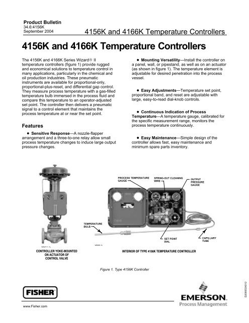
Product Bulletin34.6:<strong>4156K</strong>September 2004<strong>4156K</strong> <strong>and</strong> <strong>4166K</strong> <strong>Temperature</strong> <strong>Controllers</strong><strong>4156K</strong> <strong>and</strong> <strong>4166K</strong> <strong>Temperature</strong> <strong>Controllers</strong>The <strong>4156K</strong> <strong>and</strong> <strong>4166K</strong> Series Wizard IItemperature controllers (figure 1) provide rugged<strong>and</strong> economical solutions to temperature control inmany applications, particularly in the chemical <strong>and</strong>oil production industries. These pneumaticinstruments are available for proportional-only,proportional-plus-reset, <strong>and</strong> differential gap control.They measure process temperature with a gas-filledtemperature bulb immersed in the process fluid <strong>and</strong>compare this temperature to an operator-adjustedset point. The controller then delivers a pneumaticsignal to a control element that maintains theprocess temperature at or near the set point.Features Sensitive Response—A nozzle-flapperarrangement <strong>and</strong> a three-to-one relay allow smallprocess temperature changes to induce large outputpressure changes. Mounting Versatility—Install the controller ona panel, wall, or pipest<strong>and</strong>, as well as on an actuator(as shown in figure 1). The temperature element isadjustable for desired penetration into the processvessel. Easy Adjustments—<strong>Temperature</strong> set point,proportional b<strong>and</strong>, <strong>and</strong> reset are adjustable withlarge, easy-to-read dial-knob controls. Continuous Indication of Process<strong>Temperature</strong>—A temperature gauge, calibrated forthe specific measurement range, monitors theprocess temperature continuously. Easy Maintenance—Simple design of thecontroller allows fast, easy maintenance <strong>and</strong>minimum spare parts inventory.PROCESS TEMPERATUREGAUGESPRING-OUT CLEANINGWIREOUTPUTPRESSUREGAUGETEMPERATUREBULBSET POINTDIALCAPILLARYTUBEW4277-1 / ILCONTROLLER YOKE−MOUNTEDON ACTUATOR OFCONTROL VALVEW8086 / ILINTERIOR OF TYPE <strong>4156K</strong> TEMPERATURE CONTROLLERFigure 1. Type <strong>4156K</strong> ControllerD200053X012www.Fisher.com
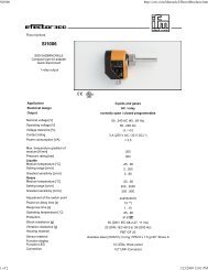
<strong>4156K</strong> <strong>and</strong> <strong>4166K</strong> <strong>Temperature</strong> <strong>Controllers</strong>Product Bulletin34.6:<strong>4156K</strong>September 2004SpecificationsAvailable ConfigurationsSee table 1Input Signal (1)Type: <strong>Temperature</strong> between 0C <strong>and</strong> 500C or0F <strong>and</strong> 1000F; see table 2 for available rangesMinimum Span (1) : 100C or 100FMaximum Span (1) : 500C or 1000FOutput Signal (1)Proportional-Only or Proportional-Plus-Reset<strong>Controllers</strong>: 0.2 to 1.0 bar (3 to 15 psig) or 0.4 to 2.0 bar (6 to 30 psig) pneumatic pressuresignalDifferential Gap <strong>Controllers</strong>: 0 <strong>and</strong> 1.4 bar (0 <strong>and</strong> 20 psig) or 0 <strong>and</strong> 2.4 bar (0 <strong>and</strong> 35 psig) pneumaticpressure signalAction: Control action is field reversible between direct (increasing sensed temperatureproduces increasing output signal) <strong>and</strong> reverse(increasing sensed temperature producesdecreasing output signal). The suffix R is addedto the type number of a construction specified forreverse action.Supply Pressure (3)See table 3Steady-State Air Consumption (1)See figure 2Supply <strong>and</strong> Output Connections0.25 inch NPT femaleMaximum Allowable Pressure in Closed Vessel(For <strong>Temperature</strong> Bulb)3/8-inch (10 mm) <strong>Temperature</strong> Bulb: 69 bar(1000 psig) at 38C (100F)9/16-inch (14 mm) <strong>Temperature</strong> Bulb: 34.5 bar(500 psig) at 38C (100F)Proportional B<strong>and</strong> (1) AdjustmentFor Proportional-Only orProportional-Plus-Reset <strong>Controllers</strong>Full output pressure change adjustable overpercent of sensing element temperature range asfollows:Proportional-Only <strong>Controllers</strong>: 3% to 100% [0.2 to 1.0 bar (3 to 15 psig)] or 6% to 100% [0.4 to 2.0 bar (6 to 30 psig)]Proportional-Plus-Reset <strong>Controllers</strong>: 6% to 200% [0.2 to 1.0 bar (3 to 15 psig)] or 12% to 200% [0.4 to 2.0 bar (6 to 30 psig)]Differential Gap AdjustmentFor Differential Gap <strong>Controllers</strong>: Full outputpressure change adjustable from 15% to 100% ofsensing element temperature rangeReset (1) AdjustmentFor Proportional-Plus-Reset <strong>Controllers</strong>:Adjustable from 0.01 minutes to more than 74minutes per repeat (from 100 repeats per minuteto less than 0.0135 repeats per minute)PerformanceRepeatability (1) : 0.5% of sensing elementtemperature rangeDead B<strong>and</strong> (1) (Except Differential Gap<strong>Controllers</strong> (2) ): 0.1% of output spanTime Constant of <strong>Temperature</strong> Bulb: 9 to 18seconds (bare bulb in agitated liquid)Ambient Operating <strong>Temperature</strong> Limits (3)-40 to 71C (-40 to 160F)Typical Ambient <strong>Temperature</strong> OperatingInfluenceProportional Control Only: Output pressurechanges ±3.0% of sensing element range foreach 28C (50F) change in ambient temperaturefor a controller set at 100% proportional b<strong>and</strong>Reset Control Only: Output pressure changes±2.0% of sensing element range for each 28C(50F) change in ambient temperature for acontroller set at 100% proportional b<strong>and</strong>Process <strong>Temperature</strong> IndicationSt<strong>and</strong>ard on all controllers <strong>and</strong> calibrated for thetemperature range orderedHazardous Area ClassificationComplies with the requirements of ATEX Group IICategory 2 Gas <strong>and</strong> DustCapillary LengthsSt<strong>and</strong>ard: 4.6 m (15 foot)Optional: Consult your Fisher sales office salesoffice for other lengthsApproximate Weight8.2 kg (18 pounds)-continued -2
Product Bulletin34.6:<strong>4156K</strong>September 2004<strong>4156K</strong> <strong>and</strong> <strong>4166K</strong> <strong>Temperature</strong> <strong>Controllers</strong>Specifications (continued)Construction MaterialsSee table 4Output Pressure Gauge IndicationsSee table 5Options Stainless steel bellows <strong>and</strong> stainless steelrelay1. These terms are defined in ISA St<strong>and</strong>ard S51.1.2. An adjustable differential gap (differential gap controllers) is equivalent to an adjustable deadb<strong>and</strong>.3. The pressure/temperature limits in this bulletin <strong>and</strong> any applicable st<strong>and</strong>ard or code limitation should not be exceeded.Table 1. Available ConfigurationsType Number (1)Proportional-Plus-Proportional-OnlyResetDifferential GapAnti-Reset Windup<strong>4156K</strong>X<strong>4156K</strong>SX<strong>4166K</strong>X<strong>4166K</strong>F X X1. The suffix R is added to the type number of a construction specified for reverse action.Table 2. <strong>Temperature</strong> Ranges of <strong>Temperature</strong> Element Assemblies (1)TEMPERATURE SPAN, C TEMPERATURE RANGE, C OVERRANGE LIMITS, C (2)100 0 to 100 200150 0 to 150 200200 0 to 200 330250 0 to 250 500300 0 to 300 500400 0 to 400 500500 0 to 500 600TEMPERATURE SPAN, F TEMPERATURE RANGE, F OVERRANGE LIMITS, F (2)0 to 100 20010050 to 150 225100 to 200 250150 50 to 200 3702000 to 200 47050 to 250 435300 0 to 300 400400 0 to 400 780600 0 to 600 870800 0 to 800 10001000 0 to 1000 12001. Class IIIB per SAMA St<strong>and</strong>ard RC6-10.2. With 4.6 m (15 foot) capillary tube. If these limits are exceeded, a permanent zero shift may result.Table 3. Supply Pressure RequirementsOUTPUT SIGNAL RANGENORMAL OPERATINGSUPPLY PRESSURE (1)MAXIMUM ALLOWABLESUPPLY PRESSURE TOPREVENT INTERNALPART DAMAGE (2)Bar Psig Bar Psig Bar Psig0.2 to 1.0(0 <strong>and</strong> 1.4 differential gap)0.4 to 2.0(0 <strong>and</strong> 2.4 differential gap)1. If this pressure is exceeded, control may be impaired.2. If this pressure is exceeded, damage to the controller may result.3 to 15(0 <strong>and</strong> 20 differential gap)6 to 30(0 <strong>and</strong> 35 differential gap)1.4 20 2.8 402.4 35 2.8 403
<strong>4156K</strong> <strong>and</strong> <strong>4166K</strong> <strong>Temperature</strong> <strong>Controllers</strong>Product Bulletin34.6:<strong>4156K</strong>September 2004Table 4. Construction MaterialsPartMaterialThermal element assembly (1)Stainless steelInterior TubingStainless steelExterior TubingCopper (with or without PVC plastic lining), stainless steel, or synthetic rubberExterior fittingsBrass or stainless steelNozzle <strong>and</strong> reversing blockStainless steel/zincRelay springs <strong>and</strong> spring plateStainless steelRelay diaphragmsNitrileOther metal relay parts, proportional bellows, <strong>and</strong>/orexhaust/reset bellowsAluminum/brass or aluminum/stainless steelReset valve assembly <strong>and</strong> differential relief valve(Types <strong>4166K</strong> <strong>and</strong> <strong>4166K</strong>F controllers only)Aluminum/brass/zinc/plated steelO-ringsNitrileGasketsNeopreneCoverMarine-grade aluminum (Alloy 13) with glass gauge windowsCase <strong>and</strong> set point dialAluminumProportional valve assemblyBrass/plated steel or stainless steelFlapper Invar 36Control linkMonel <strong>and</strong>/or stainless steelFlexure <strong>and</strong> temperature setting adjustment assembliesAluminum/steel/stainless steel/plasticCalibration adjusterZincBushing (2)Brass (3) or stainless steelThermowell (2)Brass (3) carbon steel, Monel, or stainless steel1. Contacts the process fluid unless used in a thermowell.2. Contacts the process fluid.3. For use with 10 mm (3/8 inch) diameter temperature bulb only.Table 5. Output Pressure GaugesGAUGE SCALEFor .2 to 1.0 Bar (3 to 15 psig) or0 <strong>and</strong> 1.4 Bar (0 <strong>and</strong> 20 psig) OutputGAUGE RANGEFor 0.4 to 2.0 Bar (6 to 30 Psig) or0 <strong>and</strong> 2.4 Bar (0 <strong>and</strong> 35 psig) OutputTriple 0 to 30 psig/0 to 0.2 MPa/0 to 2 Bar 0 to 60 psig/0 to 0.4 MPa/0 to 4 BarDual 0 to 30 psig/0 to 2 kg/cm 2 0 to 60 psig/0 to 4 kg/cm 221.07.94PROPORTIONAL BANDSETTING OF 5.80.67.54.40.27PROPORTIONALBAND SETTING OF 0.13OR 1000 .21 .34 .48 .62 .76 .90 1.03 1.17SUPPLY AIR FLOW, M 3 /HROUTPUT, BAR 10.2 TO 1.0 BAR (3 TO 15 PSIG) OUTPUT SIGNAL RANGENOTES1 TO CONVERT BAR TO PSIG DIVIDE BY 0.06895.2 M 3 /HR-NORMAL CUBIC METERS PER HOUR (0C AND 1.01325 BAR,ABSOLUTE) TO CONVERT TO SCFH-STANDARD CUBIC FEET PER HOUR(60F AND 14.7 PSIG) DIVIDE BY 0.0268E0473 / IL2SUPPLY AIR FLOW, M 3 /HR1.07PROPORTIONAL.94 BAND SETTING OF 5.80.67.54.40.27PROPORTIONAL BANDSETTING OF 0 OR 10.1300 .41 .69 .97 1.2 1.5 1.8 2.1 2.3OUTPUT, BAR 10.4 TO 2.0 BAR (6 TO 30) OUTPUT SIGNAL RANGEFigure 2. Steady-State Air Consumption4
Product Bulletin34.6:<strong>4156K</strong>September 2004<strong>4156K</strong> <strong>and</strong> <strong>4166K</strong> <strong>Temperature</strong> <strong>Controllers</strong>TO PROPORTIONALBELLOWSTO RESET BELLOWSPROPORTIONALBANDADJUSTMENTRESETADJUSTMENTSUPPLY PRESSUREEXHAUSTEXHAUST ENDOF RELAY VALVEBOURDONTUBEINLET END OFRELAY VALVESMALL DIAPHRAGMLARGE DIAPHRAGMFIXED ORIFICEFROMRELAYPROPORTIONALBELLOWSSET POINTADJUSTMENTPROPORTIONAL−PLUS−RESET CONTROLWITH ARROW DOWN-RELIEVES ONDECREASING OUTPUT(OUTPUT AT SUPPLYDURING SHUTDOWN)BEAM ANDFLAPPERNOZZLERESETBEL-LOWSPROPORTIONALBANDADJUSTMENTDIFFERENTIALRELIEFVALVEVENTEDOUTPUTTO PROPORTIONALBELLOWSTEMPERATUREELEMENT PRESSURESUPPLY PRESSURETEMPERATUREBULBTO RESET BELLOWSRESETADJUST-MENTOUTPUT PRESSURE38B6006-C38B6019-AB2347-2 / ILNOZZLE PRESSUREPROPORTIONALPRESSURERESET PRESSUREPROPORTIONAL−ONLY CONTROLFROMRELAYPROPORTIONALBANDADJUSTMENTPROPORTIONAL−PLUS−RESET CONTROLWITH ANTI−RESET WINDUPFigure 3. Schematic of <strong>4156K</strong> <strong>and</strong> <strong>4166K</strong> Series <strong>Temperature</strong> <strong>Controllers</strong>Principle of OperationFigures 3, 4, <strong>and</strong> 5 show construction variationsbetween the controllers. Table 1 relates constructionvariations to type numbers.Proportional-Only <strong>Controllers</strong>Refer to figures 3 <strong>and</strong> 4.As the process temperature increases, pressureincreases within the Bourdon tube extending itsradius of arc. This moves the flapper toward thenozzle (in a direct-acting controller) restricting flowthrough the nozzle <strong>and</strong> increasing nozzle pressure.When this occurs, relay action increases the outputpressure of the controller.With a Type <strong>4156K</strong> proportional-only controller, aportion of the output pressure is fed back to theproportional bellows. The action of the proportionalbellows counters the flapper movement that resultedfrom the process temperature change <strong>and</strong> backs theflapper away from the nozzle until equilibrium isattained. The proportional b<strong>and</strong> adjustmentdetermines the amount of output pressure that is fedback to the proportional bellows. Adjusting theproportional b<strong>and</strong> changes the gain of the controller.5
<strong>4156K</strong> <strong>and</strong> <strong>4166K</strong> <strong>Temperature</strong> <strong>Controllers</strong>Product Bulletin34.6:<strong>4156K</strong>September 2004Proportional-Plus-Reset <strong>Controllers</strong>Refer to figures 3 <strong>and</strong> 5.Operation of the Type <strong>4166K</strong> Proportional-plus-resetcontroller is similar to that of the proportional-onlycontroller except that output pressure is fed back tothe reset bellows, through a reset restriction valve,as well as to the proportional bellows. The action ofthe reset bellows opposes that of the proportionalbellows. However, because of the reset restrictionvalve, the action of the reset pressure is delayed.The reset valve can be adjusted to vary the delaytime. In operation, proportional-plus-reset controllersminimize the offset between the processtemperature <strong>and</strong> set point.W8093 / ILREVERSINGBLOCKVENTED BELLOWSPROPORTIONALBELLOWSFigure 4. Direct-Acting Type <strong>4156K</strong> ControllerRESET VALVEPROPORTIONAL BELLOWSW8085 / ILRESET BELLOWSFigure 5. Direct-Acting Type <strong>4166K</strong> ControllerThe set point adjustment changes the proximity ofthe nozzle <strong>and</strong> flapper as does a change in processtemperature. When the set point is changed,however, the nozzle moves with respect to theflapper.As shown in figure 6, moving the reversing block <strong>and</strong>bellows connection changes the controller actionfrom direct to reverse, <strong>and</strong> vice versa. Withreverse-acting controllers, an increase in processtemperature causes a decrease in output pressure.Anti-Reset WindupThe Type <strong>4166K</strong>F controller has an adjustable <strong>and</strong>reversible differential relief valve to provide anti-resetwindup. As shown in figure 3, the proportionalpressure registers rapidly on the spring side of therelief valve diaphragm as well as in the proportionalbellows. Reset pressure registers slowly on theopposite side of the relief valve diaphragm. As longas the controller output pressure changes are slowenough for normal proportional <strong>and</strong> reset action, therelief valve spring keeps the relief valve diaphragmfrom opening. However, a large or rapid decrease incontroller output pressure decreases the pressure inthe proportional system, <strong>and</strong> on the spring side ofthe relief diaphragm. If the decrease on the springside of the diaphragm is greater than the relief valvespring setting, the diaphragm will move off the reliefvalve orifice <strong>and</strong> permit the reset pressure on theopposite side of the relief valve diaphragm to bleedrapidly into the proportional system. The differentialrelief valve can also be reversed to relieve with anincreasing output pressure.Differential Gap <strong>Controllers</strong>In the Type <strong>4156K</strong>S controllers, feedback pressuredoes not counteract the change in flapper position.Instead, the output pressure is piped to the bellowslocated on the side of the beam <strong>and</strong> flapper oppositethe nozzle. Feedback pressure now reinforces theflapper movement by the sensed temperaturechange. This construction causes the controlleroutput to switch from full supply pressure to zeropressure or vice versa. The difference between theprocess temperature when the controller outputswitches to zero <strong>and</strong> the process temperaturewhen the controller switches to maximum is thedifferential gap. Adjusting the proportional b<strong>and</strong>adjustment adjusts the width of the gap; adjustingthe set point positions the gap within thetemperature element range.6
Product Bulletin34.6:<strong>4156K</strong>September 2004<strong>4156K</strong> <strong>and</strong> <strong>4166K</strong> <strong>Temperature</strong> <strong>Controllers</strong>PROPORTIONAL TUBINGRESET VALVEPROPORTIONALTUBINGRESETTUBINGPROPORTIONAL AND RESETTUBING LOCATIONSRESET TUBINGPROPORTIONAL AND RESETTUBING LOCATIONSPROPORTIONAL TUBINGPROPORTIONAL TUBINGREVERSINGBLOCKRELAYTUBINGREVERSEPOSITIONREVERSEACTINGPOSITIONREVERSINGBLOCKVENTEDBELLOWSPROPORTIONALBELLOWSBEAMDIRECTACTINGPOSITIONDIRECT POSITIONPROPORTIONALBELLOWSVENTEDBELLOWSPROPORTIONAL TUBING LOCATIONPROPORTIONAL TUBING LOCATIONB2319-2 / ILREVERSE−ACTING CONTROLLERSDIRECT−ACTING CONTROLLERSFigure 6. Converting from Direct to Reverse ActionConstruction FeaturesEasy Relay MaintenanceA clean-out wire provides a fast, easy means ofcleaning the primary orifice of the relay duringservice.Easy Conversion from Proportional toDifferential GapWhen the application requires differential gapcontrol, the Type <strong>4156K</strong>S controller is available. Or,a proportional-only controller can be easilyconverted to differential gap operation by reversingthe tubing connection at the bellows frame on top ofthe beam <strong>and</strong> flapper.Rugged Service CapabilityThe case <strong>and</strong> cover are made of weather resistantdie-cast aluminum. Internal constructions areavailable to resist corrosive supply pressure mediasuch as sour gas.Easy Direct/Reverse ConversionSwitching the action from direct to reverse or viceversa is done by simply moving the reversing block<strong>and</strong> feedback bellows connection as shown infigure 6.7
<strong>4156K</strong> <strong>and</strong> <strong>4166K</strong> <strong>Temperature</strong> <strong>Controllers</strong>Product Bulletin34.6:<strong>4156K</strong>September 2004Table 6. <strong>Temperature</strong> Bulb DimensionsSAMATEMPERATURE SPANSSTYLE C F B (1)AdjustableUnion(St<strong>and</strong>ardConstruction)0-100 0-100 1/2 NPSM-2B0-150 200-400 1/2 NPSM-2B0-200 0-400 1 UNEF-2B0-500 0-1000 1 UNEF-2BDIMENSIONJ X Ymm Inch mm Inch mm Inch445 17.50 145 5.70 10 0.38584 23.00 178 7.00 14 0.561. NPSM--National Straight Pipe Threads for Mechanical Joints; UNEF-UnifiedThread-Extra FineCONTROLLERLOADINGPRESSUREGAUGELOADING PRESSUREOUTPUT FROMCONTROLLERA2111-2 / ILALTERNATELOADINGPRESSURE GAUGE670 SERIES ORTYPE 671MANUAL LOADERWITH THREE-WAYCHANGEOVERVALVEALTERNATELOADINGPRESSURESOURCETO ACTUATOR AND VALVEFigure 8. Schematic of Manual Backup Changeover Hookupfor Wizard II ControllerASSPECIFIED1JMIN BEND RADIUS, 32 mm (1.25 INCHES)6.4 (0.25) ARMORNOTE:1 4.6 mm (15 FOOT) LENGTH ISSTANDARD. OPTIONAL LENGTHS AREAVAILABLE. MINIMUM BENDING RADIUS XIS 32 mm (1.25 INCHES)2 USED WITH EITHER BUSHINGOR THERMOWELL CONNECTIONYPARTS PER SAMA RC6-10-196335A5694-5A2877-6 / ILADJUSTABLE UNION 23/8 INCH BULB = 7/8 INCH HEX9/16 INCH BULB = 1-1/8 INCH HEX1/2-14 NPSM (7/8 INCH HEX)1-20 UNEF-2A (1-1/8 INCH HEX)MIN BEND RADIUS,32 mm (1.25 INCHES)mm(INCH)Figure 7. <strong>Temperature</strong> Bulb Dimensions (also see table 6)Manual BackupAs shown in figure 8, a 670 or 671 Seriespanel-mounted loading regulator with changeovervalve permits switching to an alternate loadingpressure in the event of a supply pressure failure orother malfunction.Anti-Reset WindupThe anti-reset windup capability of the Type <strong>4166K</strong>Fcontroller provides quick equalization of reset <strong>and</strong>proportional pressures. This capability reducesovershoot of the process temperature that can resultfrom large or prolonged deviation from set point.The differential relief valve has a range of 0.14 to 0.4bar (2 to 7 psig) <strong>and</strong>, unless ordered otherwise, isset by the factory to relieve at a 0.3 bar (5 psi)difference between proportional <strong>and</strong> reset pressures.The valve can be positioned to relieve on eitherincreasing or decreasing output pressure.8
Product Bulletin34.6:<strong>4156K</strong>September 2004<strong>4156K</strong> <strong>and</strong> <strong>4166K</strong> <strong>Temperature</strong> <strong>Controllers</strong>Table 7. Bushing DimensionsTEMPERATUREBULBA (1) B Without Lagging With LaggingDIAMETERC C D Emm Inch mm Inch mm Inch mm Inch mm Inch mm Inch10 3/8 1/2-14 NPSM 11 0.44 11 0.44 12 0.47 113 4.44 11 0.4414 9/16 1-20 UNEF 19 0.75 16 0.63 17 0.66 121 4.75 16 0.631. Seat area per SAMA St<strong>and</strong>ard RC-17-10.Table 8. Thermowell DimensionsTEMPERATURE BULBDIAMETERmmInch10 3/8A0.5 14 NPT0.75 14 NPTmm1620BInch0.630.77U (INSERTION LENGTH)C (1)mm Inch1/2 14 NPSM-2B14 9/16 0.75 14 NPT 22 0.88 1-20 UNEF-2B1. Seat area per SAMA St<strong>and</strong>ard RC-17-10.1912674061912674065597.510.5167.510.51624B44(1.75)C44(1.75) 25(1.00)UAB0.75 14 NPTBUSHINGS WITHOUT LAGGINGCTHERMOWELLS WITHOUT LAGGINGBD121(4.75)25(1.00)UECBABUSHINGS WITH LAGGING0.75 NPTNOTES:1 TOLERANCES FOR THIS DIMENSION ARE AS FOLLOWS:1.5 mm (±0.06 INCH) WHEN LENGTH IS 305 mm (12 INCHES) OR LESS3.2 mm (±0.125 INCH) WHEN LENGTH IS GREATER THAN 305 mm (12 INCHES)2 1-1/8 INCH HEX FOR 3/8-INCH TEMPERATURE BULB;1-1/4 INCH HEX FOR 9/16-INCH TEMPERATURE BULBA3240-3* / ILCTHERMOWELLS WITH 76 mm (3−INCH) LAGGINGFigure 9. Bushing <strong>and</strong> Thermowell Dimensions (also see tables 7 <strong>and</strong> 8)9
<strong>4156K</strong> <strong>and</strong> <strong>4166K</strong> <strong>Temperature</strong> <strong>Controllers</strong>Product Bulletin34.6:<strong>4156K</strong>September 200460(2.38)DIA23(0.91)16(0.62)181(6.82)VENTCASE TAPPED0.25 NPTBRACKETCAP SCREWPANEL MOUNTING145(5.69)WALL MOUNTINGRIGHT SIDE VIEW SHOWINGPIPESTAND MOUNTINGLEFT SIDE VIEW241(9.50)37.6(1.48)238(9.38)DETAIL OF PROPORTIONAL-PLUS-RESETCONTROLLER WITH ANTI-RESETWINDUP RELIEF VALVEOUTPUTCONNECTION0.25 NPTFRONT VIEW69(2.72)SUPPLY CONNECTION0.25 INCH NPT244(9.62)216(8.50)23(0.91)66(2.59)51(2.00)51(2.00)219(8.62)14.2R(0.56)102(4.00)19B3110-A15A7451-C122(4.81)64(2.50)64(2.50)122(4.81)BACK VIEWCAPILLARYTUBE4 HOLESFOR WALLMOUNTINGCUTOUT DIMENSIONS FOR PANELMOUNTING AND HOLE LOCATIONSFOR WALL MOUNTINGmm(INCH)15A7452-FB2320-3 / ILGE07082-AFigure 10. Controller Dimensions10
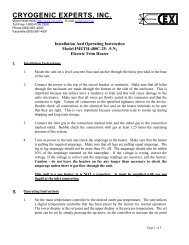
Product Bulletin34.6:<strong>4156K</strong>September 2004<strong>4156K</strong> <strong>and</strong> <strong>4166K</strong> <strong>Temperature</strong> <strong>Controllers</strong>InstallationProcess temperature is sensed by a temperaturebulb immersed in the process fluid. <strong>Temperature</strong>bulb dimensions are shown in figure 7 <strong>and</strong> table 6.Mounting the temperature bulb in a closed vesselrequires a bushing or thermowell. Figure 9 <strong>and</strong>tables 7 <strong>and</strong> 8 show the dimensions of variousbushings <strong>and</strong> thermowells available. When thetemperature bulb is used within a closed vessel, thebulb screws into a bushing that penetrates thevessel. If the pressure within the closed vesselexceeds the limits of the temperature bulb, or if theprocess fluid is corrosive, the temperature bulbscrews into a thermowell that penetrates the vessel.Lag type bushings <strong>and</strong> thermowells are used whereextra length is required, such as installation in aprocess vessel that is coated with insulation.WIZARD IICONTROLLERTYPE 657ACTUATOR67 SERIESFILTERREGULATORThe controller must be installed within the capillarytube length of the temperature bulb. Basic controllerdimensions as well as dimensions for specificmounting configurations are shown in figure 10.Install the controller so that the vent points down.These temperature controllers are often mounted onthe actuator of a control valve. Typical yokemounting of a controller <strong>and</strong> regulator on a controlvalve actuator is shown in figure 11.W8102 / IL3. Ambient temperatureFigure 11. Typical Yoke Mounting4. Velocity of process fluid (if measuring thetemperature of a process fluid flowing through apipe)5. Pressure in process vessel (if closed)Ordering InformationNote: Fisher does not assume responsibility forthe selection, use, or maintenance of anyproduct. Responsibility for proper selection, use,<strong>and</strong> maintenance of any Fisher product remainssolely with the purchaser <strong>and</strong> end user.When ordering, specify:Application1. Description of the service2. <strong>Temperature</strong> range of the process6. Bushing or thermowell (when the temperaturebulb is to be used in a closed vessel). Refer to figure8 for available sizes. Specify straight shank ortapered shank thermowell. (Tapered-shankthermowells, with their high strength-to-weight ratio,permit operation in higher process fluid velocitiesthan do straight-shank thermowells.)ConstructionRefer to the specifications <strong>and</strong> the ConstructionFeatures section. Review each specification <strong>and</strong>feature, specifying your choice whenever a selectionis offered. A panel mounting bracket is suppliedunless some other mounting method is specified.Specify the quantity <strong>and</strong> the complete type number(including the R suffix for reverse action) for theWizard II controller.11
<strong>4156K</strong> <strong>and</strong> <strong>4166K</strong> <strong>Temperature</strong> <strong>Controllers</strong>Product Bulletin34.6:<strong>4156K</strong>September 2004Wizard <strong>and</strong> Fisher are marks owned by Fisher Controls International LLC, a member of the Emerson Process Management business division ofEmerson Electric Co. The Emerson logo is a trademark <strong>and</strong> service mark of Emerson Electric Co. All other marks are the property of theirrespective owners.The contents of this publication are presented for informational purposes only, <strong>and</strong> while every effort has been made to ensure their accuracy, they arenot to be construed as warranties or guarantees, express or implied, regarding the products or services described herein or their use or applicability.We reserve the right to modify or improve the designs or specifications of such products at any time without notice.Fisher does not assume responsibility for the selection, use or maintenance of any product. Responsibility for proper selection, use <strong>and</strong>maintenance of any Fisher product remains solely with the purchaser <strong>and</strong> end-user.Emerson Process ManagementFisherMarshalltown, Iowa 50158 USACernay 68700 FranceSao Paulo 05424 BrazilSingapore 128461www.Fisher.comFisher 12 Controls International LLC 1982, 2004; All Rights ReservedPrinted in USA