LESLIE CLASS DLO(S)-2 CAGE-RETAINED TRIM ... - CEXI
LESLIE CLASS DLO(S)-2 CAGE-RETAINED TRIM ... - CEXI
LESLIE CLASS DLO(S)-2 CAGE-RETAINED TRIM ... - CEXI

Create successful ePaper yourself
Turn your PDF publications into a flip-book with our unique Google optimized e-Paper software.
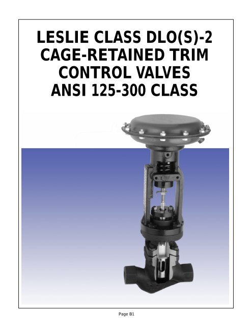
<strong>LESLIE</strong> <strong>CLASS</strong> <strong>DLO</strong>(S)-2<br />
<strong>CAGE</strong>-<strong>RETAINED</strong> <strong>TRIM</strong><br />
CONTROL VALVES<br />
ANSI 125-300 <strong>CLASS</strong><br />
Page B1
<strong>CLASS</strong> <strong>DLO</strong>(S)-2 <strong>CAGE</strong>-<strong>RETAINED</strong> <strong>TRIM</strong> CONTROL VALVES<br />
Leslie’s Class <strong>DLO</strong>(S)-2 cage-retained control<br />
valves are designed for general purpose control of<br />
clean, dirty, viscous or corrosive liquids, as well as low<br />
to medium pressure, clean or dirty steam and gas service.<br />
The cage-retained seat design eliminates the need<br />
or use of any threaded internal parts insuring ease of<br />
maintenance and parts replacement even after years<br />
in corrosive service. Top entry design also permits<br />
easy access to all internal parts for inspection or<br />
maintenance without removal of the valve from the<br />
DESIGN FEATURES<br />
pipeline. The <strong>DLO</strong>-2 class also features the highest<br />
Cv capacity of any comparable single seated valve in<br />
the industry providing maximum flows and minimum<br />
pressure losses.<br />
Two point stem guiding provides rigid plug guiding<br />
and makes these valves especially suited for controlling<br />
dirty liquids or steam.<br />
Through-bolted bonnet on cast steel and stainless<br />
steel valves, in lieu of bonnet studs, makes valve servicing<br />
easy, even after many years of service in corrosive<br />
environments.<br />
Body Materials<br />
Class <strong>DLO</strong>(S)-2 control valves are<br />
available in several body materials to handle<br />
a wide variety of applications.<br />
Standard body materials include cast iron,<br />
carbon steel (<strong>DLO</strong>S-2), and 316 stainless<br />
steel (<strong>DLO</strong>S-2). Other materials are available<br />
on request.<br />
Two Point Stem Guiding<br />
The heavy duty stem is guided at<br />
the top and bottom of the bonnet by<br />
two guide bushings. Unlike single<br />
point guiding, this method minimizes<br />
trim wear and seat leakage caused<br />
by plug deflection and vibration.<br />
Stem guiding also eliminates any<br />
possibility of pumping of fluid as can<br />
happen with post guided globe<br />
valves by eliminating the bushing<br />
cavity where media can become<br />
trapped then pumped through the<br />
packing.<br />
Tight Shut-Off<br />
Seat material<br />
choices include 316<br />
stainless steel seats<br />
with Stellite* alloy hardfacing<br />
providing ANSI<br />
Class IV or V shut-off,<br />
316 stainless steel<br />
optional. An optional<br />
316 stainless steel seat<br />
with a PTFE insert provides<br />
ANSI Class VI<br />
bubble-tight shut-off<br />
and Class IV metal-tometal<br />
back-up.<br />
End Connections<br />
<strong>DLO</strong>-2 Series valves<br />
are available in ANSI 125#<br />
250#, and (<strong>DLO</strong>S-2) series<br />
in 150# and 300# class<br />
body ratings. Choice of<br />
standard end connections<br />
include threaded, socket<br />
weld, butt weld and raised<br />
face flanged. DIN flange<br />
end connections optional.<br />
* STELLITE is a registered trademark of Stoody Deloro Stellite, Inc.<br />
Page B2
<strong>CLASS</strong> <strong>DLO</strong>(S)-2 <strong>CAGE</strong>-<strong>RETAINED</strong> <strong>TRIM</strong> CONTROL VALVES<br />
Cage-Retained Trim<br />
Leslie Class <strong>DLO</strong>-2 valves feature no internal<br />
threaded parts making them ideally suited for handling<br />
corrosive fluids and insuring ease of parts removal<br />
even after years of service. The non-threaded seat ring<br />
is rigidly clamped into the valve body by the bonnet<br />
and the seat retaining cage.<br />
Reduced Trim Options<br />
Class <strong>DLO</strong>-2 Series<br />
control valves offer up to<br />
five different trim sizes<br />
and flow capacities for a<br />
given body size.<br />
Reduced trim options<br />
provide controllable Cv’s<br />
from .02 to 57. For metering<br />
applications,<br />
Microtaper* trim provides<br />
Cv’s as low as .01. Multiple<br />
trim selections provide<br />
optimized valve sizing,<br />
allow for future capacity<br />
increases, control<br />
of body velocities and<br />
easy correction of oversized<br />
valve problems.<br />
One Piece Stem/Plug<br />
One piece plug and<br />
stem eliminates any possibility<br />
of separation due<br />
to vibration and ensures<br />
correct plug/stem alignment<br />
at assembly for<br />
accurate seating and<br />
tight shut-off.<br />
Stem Wrench Flats<br />
Wrench flats on the stem provide convenient means<br />
for holding the valve stem during disassembly without<br />
risk of damaging the 8 micro-inch sealing surface.<br />
Bolted Yoke<br />
Conventional valves with the lock-nut actuator<br />
mounting design are easily ruined and scrapped due to<br />
corrosion. Leslie valves use a 4-bolt actuator mounting<br />
design which guarantees ease of disassembly no<br />
matter how corrosive the environment.<br />
APPLICABLE INDUSTRY STANDARDS<br />
All Leslie control valves are 100% factory tested and<br />
serialized. Leslie Controls’ quality assurance program is<br />
accredited and certified to ISO 9001†. All Leslie control<br />
valves are also designed, built and tested to meet the<br />
following industry standards.<br />
ANSI B1.20.1 Pipe Threads - Conforms to pipe thread<br />
requirements.<br />
ANSI B16.1 Cast Iron Flanges and Flanged Fittings -<br />
Conforms to wall thickness, flange dimensions, materials,<br />
pressure/temperature ratings, markings and hydrostatic<br />
test requirements.<br />
ANSI B16.5 Pipe Flanges and Flanged Fittings -<br />
Conforms to flange thickness, diameter and drilling<br />
requirements.<br />
ANSI B16.10 Face-To-Face Dimensions - Conforms<br />
to globe style control valve face-to-face dimension<br />
requirements.<br />
ANSI B16.25 Butt-welding Ends - Conforms to<br />
requirements of Schedule 40 or Schedule 80 pipe,<br />
without backing rings.<br />
ANSI B16.34 Valves, Flanged and Butt-weld - Integral<br />
flanged and BWE valve conforms to wall thickness,<br />
materials, pressure/temperature ratings, markings, and<br />
hydrostatic test requirements.<br />
ANSI B16.37 Hydrotesting of Control Valves - Conforms<br />
to hydrotesting requirements.<br />
ANSI/ISA 70-2 Control Valve Seat Leakage - Conforms<br />
to Class III, IV, and V shutoff requirements.<br />
ISA S75.01 Flow Equations for Sizing Control Valves.<br />
ISA S75.02 Control Valve Capacity Test Procedure -<br />
Conforms to flow capacity test procedure requirements.<br />
ISA S75.03 Uniform Face-To-Face Dimensions for<br />
Flanged Globe Style Control Valves - Conforms to faceto-face<br />
dimension requirements.<br />
ISA S75.12 Face-To-Face Dimensions for Socketweld<br />
End and Screwed End Globe Style Control Valves -<br />
Conforms to face-to-face dimension requirements.<br />
ISA S75.15 Face-To-Face Dimensions for Butt-weld<br />
End Globe Style Control Valves - Conforms to face-toface<br />
dimension requirements.<br />
MSS SP25 Standard Marking System for Valves,<br />
Fittings, Flanges, and Unions - Conforms to marking<br />
requirements for flanged, screwed and weld end fittings.<br />
MSS SP84 Steel Valves, Socketweld End and Threaded<br />
End - Conforms to end connection requirements.<br />
In addition, when required, Leslie control valves can<br />
be manufactured and tested in compliance with:<br />
CAN 3 Z299.3<br />
ANSI N45.2<br />
MIL-I-STD-45662<br />
MIL-I-45208<br />
B 31.1<br />
† Assessed and certified by ABS, Houston, Texas<br />
* MICROTAPER is a registered trademark of Leslie Controls, Inc.<br />
Page B3
<strong>CLASS</strong> <strong>DLO</strong>(S)-2 <strong>CAGE</strong>-<strong>RETAINED</strong> <strong>TRIM</strong> CONTROL VALVES<br />
GENERAL SPECIFICATIONS<br />
BODY ASSEMBLY:<br />
Style: Single seated, top entry bolted bonnet,<br />
globe style body, cage retained seat,<br />
unbalanced plug<br />
ANSI Body Ratings:<br />
Cast Iron: Class 125 & 250<br />
(DIN ND16 & ND25)<br />
Steel and alloys: Class 150 & 300<br />
(DIN ND 16 & ND40)<br />
BODY/BONNET MATERIALS:<br />
Cast Iron, ASTM A126 Class B<br />
Carbon Steel, ASTM A216 Gr WCB<br />
316 stainless steel, ASTM A351 Gr CF8M<br />
Note: See ANSI B16.1 (cast iron) or ANSI<br />
B16.34 (other materials), or Leslie<br />
Engineering Data Sheet 5/0.3.3 for pressure/temp.<br />
limits of body/bonnet assemblies.<br />
SIZES: 1 ⁄2" - 4"<br />
END CONNECTIONS:<br />
ANSI Class 125/150 Integral Flanged, 1"- 4"<br />
ANSI Class 250/300 Integral Flanged, 1"- 4"<br />
Threaded, NPT - 1 ⁄2"- 2":<br />
Cast iron - ANSI Class 250 rated<br />
Steel & alloys - ANSI Class 300 rated<br />
Socket weld ends (Sch. 40) 1 ⁄2" - 2"<br />
Butt weld ends (Sch. 40) 2 1 ⁄2" - 4"<br />
END CONNECTIONS (cont'd.):<br />
DIN Flanges: ND-16, ND-25,<br />
ND-40, ND-100<br />
BONNET:<br />
Through-bolted bonnet<br />
BODY/BONNET BOLTING:<br />
ASTM A-193 GRB7 Studs<br />
ASTM A-194 GR2H Nuts<br />
STEM PACKING:<br />
PTFE V-Rings, -40 to 460˚F (-22 to 238˚C)<br />
Braided PTFE/Graphite (Split-ring),<br />
-40 to 500˚F (-22 to 260˚C)<br />
Laminated Graphite,-320 to 800˚F<br />
(-195 to 426˚C)<br />
PACKING STUDS, NUTS & FOLLOWER:<br />
300 Series Stainless Steel<br />
GASKETS:<br />
Body gasket: Spiral wound AISI Type 316L<br />
Seat/Body Gasket:<br />
<strong>DLO</strong>-2 - Filled PTFE, 460ºF (238ºC)<br />
<strong>DLO</strong>S-2 - Graphite filled Inconel* 600<br />
750ºF (399ºC)<br />
<strong>TRIM</strong> SIZES:<br />
Full, reduced port<br />
FLOW CHARACTERISTICS:<br />
Linear or equal percent - standard<br />
Modified linear - optional<br />
SHUT-OFF <strong>CLASS</strong>:<br />
Metal/metal seats - ANSI/ISA 70-2 Class IV,<br />
Class V optional to 750ºF (399ºC)<br />
Metal/PTFE seats - ANSI/ISA 70-2 Class VI,<br />
bubble-tight to 460ºF (238ºC)<br />
TYPICAL SPECIFICATION<br />
All globe style control valves shall be designed, built and tested in accordance with the following industry<br />
standards:<br />
ANSI B1.20.1 ANSI B16.10 ANSI\ISA 70-2 MSSSP25<br />
ANSI B16.1 ANSI B16.34 ISA S75.01 MSSSP84<br />
ANSI B16.5 ANSI B16.37 ISA 75.02<br />
Control Valves shall be single seated globe style<br />
body with bolted bonnets.<br />
Valves shall have cage-retained seat trim and<br />
contain no internal threaded parts.<br />
Valve trim shall be 316 stainless steel or 316<br />
stainless steel with Stellite alloy overlay. Specified<br />
valve plug and stem assembly shall be of an integral<br />
one piece design threaded and pinned connections<br />
are not acceptable. Valve stems shall be of 316 stainless<br />
steel with an 8 micro-inch finish or better, and<br />
provided with wrench flats at the top.<br />
Valves shall be designed to accept two reduced<br />
trim options.<br />
Valves shall be provided with two replaceable<br />
stem guides of Nitronic** 60 or equal.<br />
Actuators shall be of the spring and diaphragm<br />
type, normally open or normally closed, as specified.<br />
Actuators shall have an external spring adjusting<br />
nut to facilitate bench set adjustments.<br />
Adjustable packing shall be provided by means of<br />
a packing follower, packing clamp, studs and nuts, all<br />
of 300 series stainless steel construction.<br />
* INCONEL is a registered trademark of Huntington Alloy, Inc.<br />
** NITRONIC is a registered trademark of Armco, Inc.<br />
Page B4
<strong>CLASS</strong> <strong>DLO</strong>(S)-2 <strong>CAGE</strong>-<strong>RETAINED</strong> <strong>TRIM</strong> CONTROL VALVES<br />
Temperature ºF<br />
Metal Seated Trim<br />
Pressure Drop (MPa)<br />
0 .68 1.38 2.07 2.76 3.45 4.14 4.83 5.52<br />
1200<br />
1000<br />
800<br />
600<br />
400<br />
200<br />
316<br />
0<br />
Stellite<br />
Trim<br />
-200<br />
316<br />
Trim<br />
-300<br />
0 100 200 300 400 500 600 700 800<br />
Pressure Drop (psi)<br />
648<br />
537<br />
426<br />
315<br />
204<br />
93<br />
-18<br />
-129<br />
-184<br />
Temperature ºC<br />
<strong>TRIM</strong> SELECTION DATA<br />
Temperature ºF<br />
Soft Seated Trim<br />
Pressure Drop (MPa)<br />
0 .68 1.38 2.07 2.76 3.45 4.14 4.83 5.52<br />
500<br />
400<br />
300<br />
200<br />
100<br />
0<br />
-100<br />
316 Soft Seated Trim<br />
-200<br />
-300<br />
0 100 200 300 400 500 600 700 800<br />
Pressure Drop (psi)<br />
260<br />
204<br />
149<br />
93<br />
38<br />
-18<br />
-73<br />
-129<br />
-184<br />
Temperature ºC<br />
% of Capacity<br />
100<br />
80<br />
60<br />
40<br />
20<br />
Inherent Flow Characteristics<br />
Microtaper<br />
Linear<br />
Equal Percentage<br />
0 20 40 60 80 100<br />
% of Travel<br />
LINEAR<br />
Note: 316 stainless steel body required below 20˚F<br />
See page 6, Table 1 for material specifications<br />
Metal seat Class IV<br />
shut-off to 750˚F<br />
(399˚C)<br />
PTFE soft seat<br />
Class VI shut-off<br />
to 460˚F (238˚C)<br />
Linear<br />
Contoured<br />
Equal<br />
Percentage<br />
Microtaper ®<br />
Valve Full Port Cv’s-Reduced Trim<br />
Size Cv 1<br />
⁄4"MT 1<br />
⁄4" 1<br />
⁄2" 3<br />
⁄4" 1" 1 1 ⁄2" 2" 2 1 ⁄2" 3"<br />
1<br />
⁄2 4 .5 1.5<br />
3<br />
⁄4 9 .5 1.5 4.1<br />
1 15 .5 1.5 4.1 9.1<br />
1 1 ⁄2 30 9.3 15.2<br />
2 57 15.4 30.3<br />
2 1 ⁄2 83 30.9 57.4<br />
3 120 30.9 58<br />
4 201 58.9 126<br />
Page B5
<strong>CLASS</strong> <strong>DLO</strong>(S)-2 <strong>CAGE</strong>-<strong>RETAINED</strong> <strong>TRIM</strong> CONTROL VALVES<br />
<strong>TRIM</strong> MATERIAL SELECTION<br />
Maximum<br />
ANSI/ISA<br />
Trim Service Guide 70-2<br />
Material Temp. Plug* Seat Ring Stem Cage Bushings Shut-off<br />
316 450ºF/50˚F AISI AISI AISI ASTM<br />
Trim (232ºC/398˚C) Type 316 Type 316 Type 316 A351 CF8M Nitronic 60 IV,V**<br />
316 Stellite 750˚F AISI Type AISI Type AISI ASTM<br />
Trim (398˚C) 316 Stellite 316 Stellite Type 316 A351 CF8M Nitronic 60 IV,V**<br />
316 Soft-seated 460˚F AISI ANSI Type 316 AISI ASTM<br />
Trim (238˚C) Type 316 PTFE Insert Type 316 A351 CF8M Nitronic 60 VI<br />
* Microtaper plugs are solid Stellite alloy ** on application *** 450˚F when used with cast iron bodies.<br />
PACKING CONFIGURATIONS<br />
LIVE-LOADED PTFE - V-RING<br />
(PRESSURE)<br />
Live-loaded PTFE V-ring packing<br />
provides the most maintenance free<br />
stem seal. The V-ring packing is both<br />
pressure energized and live-loaded by a<br />
316 Stainless Steel spring to automatically<br />
compensate for packing wear.<br />
Maximum service temperature is 460˚F<br />
(238˚C). V-rings can be inverted for vacuum<br />
service.<br />
PTFE/GRAPHITE<br />
Split rings allow packing replacement<br />
without removal of actuator.<br />
Graphite impregnated PTFE provides<br />
500˚F (260˚C) service temperature, better<br />
memory and sealing than pure PTFE<br />
rings, lowered stem hysteresis, and is<br />
ideal for fluids that contain suspended<br />
particles.<br />
DOUBLE-PTFE WITH BLEED,<br />
PURGE<br />
Two sets of packing rings separated<br />
by a 316 stainless steel lantern ring can<br />
provide zero stem leakage and prevent<br />
fugitive emissions. Bonnets are 1/4"<br />
NPT drilled/tapped for connection of<br />
lubricators, water seals, bleed-off or<br />
positive inert gas purge. Maximum<br />
temperature 500˚F (260˚C).<br />
Rangeabilities<br />
1<br />
⁄4" MT (Microtaper ® ) 55:1<br />
1<br />
⁄4 - 1 ⁄2" Trim 25:1<br />
COMBINATION PRESSURE/<br />
VACUUM PACKING<br />
Inverted sets of PTFE V-ring packing<br />
provide tight sealing in valves which<br />
may be controlling pressure or vacuum<br />
at different times. Max. temperature<br />
500˚F (260˚C).<br />
LAMINATED GRAPHITE<br />
Precision die-cut laminated graphite<br />
rings provide a reliable, tight stem seal<br />
to operating temperatures of 800+˚F<br />
(426˚C).<br />
3<br />
⁄4 - 2" Trim 35:1<br />
2 1 ⁄2 - 3" Trim 40:1<br />
4" Trim 50:1<br />
Page B6
<strong>CLASS</strong> <strong>DLO</strong>(S)-2 <strong>CAGE</strong>-<strong>RETAINED</strong> <strong>TRIM</strong> CONTROL VALVES<br />
DIMENSIONS<br />
CONTROL VALVE – CAST IRON<br />
CONTROL VALVE – CAST STEEL & ST. STEEL<br />
DIMENSIONS IN INCHES<br />
DIMENSIONS IN INCHES<br />
SIZE A B C D* WGT.* SIZE A B C D* WGT.*<br />
1/2 7-3/4<br />
THREADED<br />
2-3/8 5-3/16 12-3/8 54 lb. 1/2 ----- -----<br />
THREADED<br />
----- ----- -----<br />
3/4 7-3/4 2-3/8 5-3/16 12-3/8 54 lb. 3/4 ----- ----- ----- ----- -----<br />
1 7-3/4 2-3/8 5-3/16 12-3/8 54 lb. 1 7-3/4 2-1/4 5-13/16 12-3/8 51 lb.<br />
1-1/2 9-1/4 2-3/8 7-1/2 12-3/8 63 lb. 1-1/2 9-1/4 2-3/8 7-1/2 12-3/8 62 lb.<br />
2 10-1/2 3 7-3/4 15-1/4 70 lb. 2 10-1/2 3 7-3/4 15-1/4 69 lb.<br />
125 LB ANSI FLANGE STANDARD 150 LB. ANSI FLANGE STANDARD<br />
1 7-1/4 2-1/8 5-5/8 12-3/8 54 lb. 1 7-1/4 2-1/4 5-5/8 12-3/8 54 lb.<br />
1-1/2 8-3/4 2-1/2 7-3/8 12-3/8 70 lbs. 1-1/2 8-3/4 2-1/2 7-3/8 12-3/8 70 lb.<br />
2 10 3 7-5/8 15-1/4 91 lb. 2 10 3-1/2 7-5/8 15-1/4 91 lb.<br />
2-1/2 10-7/8 3-1/2 8 15-1/4 108 lb. 2-1/2 10-7/8 3 8 15-1/4 107 lb.<br />
3 11-3/4 3-3/4 8-3/8 15-1/4 130 lb. 3 11-3/4 3-3/4 8-3/8 15-1/4 127 lb.<br />
4 13-7/8 3-1/2 10-1/8 19-5/8 231 lb. 4 13-7/8 4-7/8 10-1/8 19-5/8 271 lb.<br />
250 LB. ANSI FLANGE STANDARD 300 LB. ANSI FLANGE STANDARD<br />
1 7-3/4 2-1/8 5-3/16 12-3/8 56 lb. 1 7-3/4 2-1/4 5-3/16 12-3/8 56 lb.<br />
1-1/2 9-1/4 3-1/16 7-1/2 12-3/8 70 lbs. 1-1/2 9-1/4 3-1/16 7-1/2 12-3/8 72 lb.<br />
2 10-1/2 3-1/4 7-3/4 15-1/4 95 lb. 2 10-1/2 3 7-3/4 15-1/4 95 lb.<br />
2-1/2 11-1/2 3-3/4 8-3/16 15-1/4 114 lb. 2-1/2 11-1/2 3-7/8 8-3/16 15-1/4 116 lb.<br />
3 12-1/2 4-1/8 8-1/2 15-1/4 141 lb. 3 12-1/2 4-1/8 8-1/2 15-1/4 138 lb.<br />
4 14-1/2 5 10-5/16 19-5/8 248 lb. 4 14-1/2 4-7/8 10-5/16 19-5/8 236 lb.<br />
DIMENSIONS IN MILLIMETERS<br />
DIMENSIONS IN MILLIMETERS<br />
SIZE A B C D* WGT.* SIZE A B C D WGT.*<br />
THREADED<br />
THREADED<br />
15 197 60 142 314 23.6 kg 15 ----- ----- ----- ----- -----<br />
20 197 60 142 314 23.6 kg 20 ----- ----- ----- ----- -----<br />
25 197 60 142 314 23.6 kg 25 197 57 142 314 23.2 kg<br />
40 235 60 191 314 28.6 kg 40 235 60 191 314 28.2 kg<br />
50 267 76 197 387 31.8 kg 50 267 77 197 387 31.4 kg<br />
DIN 2533 FLANGE STANDARD (ND-16) DIN 2543 FLANGE STANDARD (ND-16)<br />
25 195 54 142 314 28.6 kg 25 197 57 142 314 24.5 kg<br />
40 230 64 187 314 31.8 kg 40 230 64 187 314 31.8 kg<br />
50 263 76 194 387 41.3 kg 50 263 78 194 387 41.3 kg<br />
80 310 95 216 387 59 kg 80 310 95 216 387 57.7 kg<br />
100 385 114 262 499 104.8 kg 100 350 123 262 499 98.5 kg<br />
DIN 2534 FLANGE STANDARD (ND-25) DIN 2545 FLANGE STANDARD (ND-40)<br />
25 198 54 142 314 25.4 kg 25 198 57 142 314 25.4 kg<br />
40 234 78 191 314 32.7 kg 40 230 78 191 314 32.7 kg<br />
50 267 82 197 387 43.2 kg 50 263 77 197 387 43.2 kg<br />
65 290 95 201 387 51.7 kg 65 290 90 201 387 52.7 kg<br />
80 310 105 216 387 64.1 kg 80 310 105 216 387 62.7 kg<br />
100 393 127 262 499 112.5 kg 100 350 123 262 499 107.1 kg<br />
• Spring & Diaphragm, Standard<br />
• Piston, Double Acting/Spring Return<br />
• Electric<br />
• Electro-Hydraulic<br />
Spring and Diaphragm Actuators<br />
Leslie spring and diaphragm actuators are available<br />
for Class DL0-2 valves in three different sizes,<br />
from 35 to 85 square inches in diaphragm area, both<br />
in direct (fail open) and reverse (fail closed) action.<br />
Leslie actuators feature long strokes, constant<br />
effective diaphragm area for linear response and high<br />
operating pressures (to 60 psi) to minimize actuation<br />
costs. Leslie actuators also feature a 4-bolt yoke<br />
mounting method (not bonnet lock-nut) to insure ease<br />
of disassembly, even after years in corrosive service.<br />
ACTUATORS<br />
As standard options, a variety of accessories<br />
can be yoke mounted including:<br />
· Positioners, Pneumatic/Electro-Pneumatic<br />
· I/P Transducers<br />
· Proximity or Limit Switches<br />
· Position Transmitters<br />
· Solenoid Valves<br />
· Integral Filter/Regulators<br />
A manual override hand operating device (HOD)<br />
is also available for manual valve operation or use as<br />
a valve travel limit stop. See product data sheets<br />
10/0.2.1 and 10/0.2.2 for complete specifications.<br />
Page B7
<strong>CLASS</strong> <strong>DLO</strong>(S)-2 <strong>CAGE</strong>-<strong>RETAINED</strong> <strong>TRIM</strong> CONTROL VALVES<br />
D(D)LO(S)-2 CONTROL VALVES CODE SELECTION CHART<br />
Class Material Valve End Actuator Bonnet Trim Accessories<br />
Size Conn. Packing<br />
U 8 5 1 A 1 A 1 D F 0<br />
1 2 3 4 5 6 7 8 9 10 11<br />
Class - Position 1<br />
U<br />
Material - Position 2, 3 & 4<br />
851 = Iron<br />
853 = Carbon Steel<br />
854 = SST<br />
Valve Size - Position 5<br />
A = 1 ⁄2<br />
B = 3 ⁄4<br />
C = 1<br />
E = 1 1 ⁄2<br />
F = 2<br />
G = 2 1 ⁄2<br />
H = 3<br />
J = 4<br />
End Connection - Position 6<br />
1 = Threaded<br />
2 = Flanged 125/150<br />
3 = Flanged 250/300<br />
4 = SWE (steel only)<br />
5 = BWE (steel only)<br />
6 = ND16,ND10/16<br />
7 = ND40 (steel only)<br />
0 = Other (Specify)<br />
* 55A(R) used on 2"-3"<br />
D(D)LO(A)(S)-2 only. 55R used<br />
on all other applicable valves.<br />
†<br />
Does not include spring or<br />
mounting kit.<br />
CODE SELECTION CHART<br />
Actuator - Position 7<br />
A = 35<br />
B = 35R<br />
C = 35 HOD<br />
D = 35R HOD<br />
E = 55<br />
F = 55R<br />
G* = 55A<br />
H* = 55AR<br />
I = 55 HOD<br />
J = 55R HOD<br />
K* = 55A HOD<br />
L* = 55AR HOD<br />
M = 85<br />
N = 85R<br />
P = 85 HOD<br />
Q = 85R HOD<br />
Bonnet& Packing - Position 8<br />
1 = Std. Bonnet, Braided<br />
Teflon ® Graphite Pkg.<br />
2 = Std. Bonnet, Teflon ® Pkg.<br />
3 = Std. Bonnet, Laminated<br />
Graphite Pkg.<br />
4 = Std. Bonnet, Double<br />
Teflon ® Pkg.<br />
Accessories - Position 11<br />
0 = No Accessories Mounted<br />
1-8 = Actual Number of<br />
Accessories Mounted †<br />
Trim - Position 9 & 10<br />
Equal %, SST 316<br />
BF = 1 ⁄4<br />
DF = 1 ⁄2<br />
GF = 3 ⁄4<br />
JF = 1<br />
LF = 1 1 ⁄2<br />
MF = 2<br />
NF = 2 1 ⁄2<br />
PF = 3<br />
RF = 4<br />
Equal %,<br />
Resilient Seat<br />
DG = 1 ⁄2<br />
GG = 3 ⁄4<br />
JG = 1<br />
LG = 1 1 ⁄2<br />
MG = 2<br />
NG = 2 1 ⁄2<br />
PG = 3<br />
RG = 4<br />
Equal %, SST 316<br />
Stellite ®<br />
BH = 1 ⁄4<br />
DH = 1 ⁄2<br />
GH = 3 ⁄4<br />
JH = 1<br />
LH = 1 1 ⁄2<br />
MH = 2<br />
NH = 2 1 ⁄2<br />
PH = 3<br />
RH = 4<br />
Linear, SST 316<br />
BJ = 1 ⁄4<br />
DJ = 1 ⁄2<br />
GJ = 3 ⁄4<br />
JJ = 1<br />
LJ = 1 1 ⁄2<br />
MJ = 2<br />
NJ = 2 1 ⁄2<br />
PJ = 3<br />
RJ = 4<br />
Linear,<br />
Resilient Seat<br />
DK = 1 ⁄2<br />
GK = 3 ⁄4<br />
JK = 1<br />
LK = 1 1 ⁄2<br />
MK = 2<br />
NK = 2 1 ⁄2<br />
PK = 3<br />
RK = 4<br />
Linear, SST 316<br />
Stellite ®<br />
BL = 1 ⁄4<br />
DL = 1 ⁄2<br />
GL = 3 ⁄4<br />
JL = 1<br />
LL = 1 1 ⁄2<br />
ML = 2<br />
NL = 2 1 ⁄2<br />
PL = 3<br />
RL = 4<br />
Microtaper is available in 1/4" Stellite only Code BB.<br />
Resilient seat <strong>DLO</strong>A, <strong>DLO</strong>AS available with full size trim.<br />
<strong>TRIM</strong> BODY SIZE (IN) ACTUATOR<br />
DIA CV STROKE 1<br />
⁄2<br />
3<br />
⁄4 1 1 1 ⁄2 2 2 1 ⁄2 3 4 35(R) 55 (R) 55A(R) 85(R)<br />
1<br />
⁄4MT 0.5 3<br />
⁄4 X X X — — — — — X X — —<br />
1<br />
⁄4 1.5 3<br />
⁄4 X X X — — — — — X X — —<br />
1<br />
⁄2 4 3<br />
⁄4 X X X — — — — — X X — —<br />
3<br />
⁄4 9 3<br />
⁄4 — X X X — — — — X X — —<br />
1 15 3<br />
⁄4 — — X † X — — — X X — —<br />
1 1 ⁄2 30 3<br />
⁄4 — — — X † X X — X X — —<br />
2 57 1 — — — — X † † X — — X X<br />
2 1 ⁄2 83 1 1 ⁄4 — — — — — X — — — — X X<br />
3 120 1 1 ⁄2 — — — — — — X — — — X X<br />
4 201 2 — — — — — — — X — — — X<br />
† Consult Factory for availability.<br />
Page B8