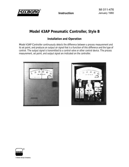
Model 43AP Pneumatic Controller, Style B - Armstrong International ...
Model 43AP Pneumatic Controller, Style B - Armstrong International ...
Model 43AP Pneumatic Controller, Style B - Armstrong International ...

Create successful ePaper yourself
Turn your PDF publications into a flip-book with our unique Google optimized e-Paper software.
Installation MI 011-476 – January 1980Installation<strong>Controller</strong> MountingMount controller level on a rigid support. If controller has Type 37 Meter, see page 8.Flush MountingAfter case is inserted in panel, install mounting brackets as shown. Slide brackets firmly againstpanel and tighten bracket bolts to case.inmmSurface MountingLoosely install mounting brackets flush with rear of case as shown. Attach brackets to panel with1/4-inch bolts or #14 wood screws. Tighten mounting bracket bolts to case.inmm5
MI 011-476 – January 1980InstallationPipe MountingRemove mounting bracket from controller case. Securely fasten bracket on a 2-inch or 3-inchpipe. Then reinstall controller into bracket.<strong>Controller</strong> Dimensions and ConnectionsFlush MountinginmmSurface Mountinginmm6
Installation MI 011-476 – January 1980Pipe MountinginmmPressure Connection1/4 NPT female (up to 2000 psi or 14 MPa)1/2 NPT male (above 2000 psi or 14 MPa)9/16-18 Aminco (from 10000 psi or 70 MPa)<strong>Pneumatic</strong> Receiver Connection1/4 compression fittingNOTEWhen installing piping, hold case connections stationary with wrench.Optional Integral Filter-Regulator SetinmmAir Supply and Output PipingFor Control Valve Piping see Instruction MI 012-210.7
MI 011-476 – January 1980Installation! WARNINGAir is usually used as controller operating gas, and it is vented directly from case.If a hazardous 1 gas is to be used instead, “GTC” option must be specified. This optionprovides a vent connection on case which can be used to pipe gas to a locationclassified for its dispersal. In addition, in normal operation some gas may bleed fromcase; therefore, classification of controller location must permit presence of this gas.1. Air supply must be regulated at 20 psi (140 kPa).2. <strong>Controller</strong> uses about 0.3 std ft 3 /min (0.5 std m 3 /h) of air in normal operation.3. Air must be clean and dry. Blow out filter regularly.4. Air lines must be free of leaks.Mounting <strong>Controller</strong> with Type 37 Meter1. See Nat’l Elect’l Code, NFPA 70, Art. 500-517.8
Installation MI 011-476 – January 1980Automatic-Manual Transfer System (optional)The automatic-manual transfer system consists of a regulator, a sensitive balance indicator, and atransfer switch. The system permits switching between manual and automatic control withoutupsetting the process.The illustration below shows the components that are concerned with the transfer system.To Transfer from Manual to Automatic ControlSlowly turn set point knob (or adjust remote set point, if present) to move balance indicator ballto within central portion of tube (not up against either end). Then turn switch to automatic (A).To Transfer from Automatic to Manual ControlTurn regulator slowly to move balance indicator ball to within central portion of tube (not upagainst either end). Turn regulator so that top of knob moves in direction that ball is to move.Then turn switch to manual (M). Valve can now be controlled with regulator.9
MI 011-476 – January 1980InstallationAutomatic-Manual TransferUsing 2-Position Nozzle Seal Switch (optional)In place of the transfer system above, a 2-position nozzle seal switch is available. Moving thisswitch to the manual (M) position, seals the nozzle line causing the output to increase to the supplypressure. The output can now be set to the desired value by reducing the pressure with anexternal supply regulator furnished by the user.To Transfer from Manual to Automatic ControlTurn set point knob (or adjust remote set point, if present) so that set point index is in line withmeasurement pointer. Move switch to automatic (A). Quickly increase air supply pressure to20 psi (140 kPa).To Transfer from Automatic to Manual OperationSlowly reduce air supply pressure to output pressure, and move switch to manual (M). Valve cannow be controlled with regulator.10
Installation MI 011-476 – January 1980Putting Into OperationFor on-off, differential gap, or automatic shutdown controllers, see page 14.1. Make sure that measuring system is properly installed and operating.2. Set control dial so that index points to desired control action (output either increasesor decreases with increasing measurement).With latch in lowered position (as shown below), control dial cannot be accidentallyrotated to area of reverse control action.To reverse control action, push up latch and rotate dial so that latch is on other side ofstop, then push down latch (see figure below).11
MI 011-476 – January 1980Installation3. Turn PROPORTIONAL BAND adjustment (on control dial) to 400 or to safe highvalue.Turn DERIVATIVE adjustment (if present) to 0.05.Turn RESET adjustment (if present) to 50 or safe high value.4. Open shutoff valves and close bypass valve.5. Turn set point knob (or adjust remote set point, if present) so that set point index is atdesired value.6. If controller is not equipped with optional automatic-manual transfer, proceed toStep 7. If controller is equipped with transfer, start up in manual as follows:a. Move transfer switch to manual (see page 9).b. Turn on 20 psi (140 kPa) air supply. Blow out filter.c. Adjust output with regulator so that measurement pointer is held as close aspossible to set point index.d. After measurement has stabilized, move transfer switch to automatic (see transferprocedure on page 9). Process is now on automatic control.7. If controller is not equipped with optional automatic-manual switch, turn on 20 psi(140 kPa) air supply. Blow out filter.8. After measurement has stabilized, adjust proportional band, derivative, and resetcontrols (if present) for best process operation (see page 13).9. With reset control, after process has stabilized with proper control settings, if set pointindex and measurement pointer do not coincide, adjust as follows:a. Loosen lockscrew.b. Adjust nylon eccentric to change index. Retighten lockscrew.12
Installation MI 011-476 – January 1980Control AdjustmentsEffect of Various Proportional Band SettingsEffect of Various Reset TimesProportional <strong>Controller</strong> (<strong>Model</strong> <strong>43AP</strong>-A2)1. Set PROPORTIONAL BAND at 400 or at safe high value.2. Make change in set point. Observe process and output responses.3. If cycling does not occur, adjust PROPORTIONAL BAND to half of previous value.4. Repeat Steps 2 and 3 until cycling is observed. Then increase PROPORTIONALBAND to twice its value.Proportional Plus Derivative <strong>Controller</strong> (<strong>Model</strong> <strong>43AP</strong>-A3)1. With DERIVATIVE at 0.05, adjust PROPORTIONAL BAND as described inProportional <strong>Controller</strong>, above.2. Adjust DERIVATIVE using same procedure as Proportional Band, except doublingeach setting instead of halving it.Proportional Plus Reset <strong>Controller</strong> (<strong>Model</strong> <strong>43AP</strong>-A4)1. With RESET at 50 or at safe high value, adjust PROPORTIONAL BAND asdescribed in Proportional <strong>Controller</strong>, above.2. Adjust RESET using same procedure as Proportional Band.Proportional Plus Reset Plus Derivative <strong>Controller</strong> (<strong>Model</strong> <strong>43AP</strong>-A5)1. With RESET at 50 or at safe high value, and DERIVATIVE to 0.05, adjustPROPORTIONAL BAND as described in Proportional <strong>Controller</strong>, above.13
Installation MI 011-476 – January 19801. If “Increasing measurement, INCREASING output” section of control dial is used,turn set point knob (or adjust remote set point, if present) to bring index to LOWERcontrol point.If “Increasing measurement, DECREASING output” is used, bring index to UPPERcontrol point.2. Rotate control dial so that arrow points to desired gap width with desired controlaction.3. When measurement pointer (moving within gap) coincides with setting index, output(on output gauge) should change suddenly. If this change does not occur when thetwo are in line, adjust index as shown on bottom of Page 7 of InstructionMI 011-477.15
MI 011-476 – January 1980InstallationISSUE DATESJAN 1980Vertical lines to right of text or illustrations indicate areas changed at last issue date.The Foxboro Company33 Commercial StreetFoxboro, MA 02035-2099United States of Americahttp://www.foxboro.comInside U.S.: 1-888-FOXBORO(1-888-369-2676)Outside U.S.: Contact yourlocal Foxboro Representative.Facsimile: (508) 549-4492Foxboro is a registered trademark of The Foxboro Company.Siebe is a registered trademark of Siebe, plc.Aminco is a trademark of American Instrument Co.Copyright 1980 by The Foxboro CompanyAll rights reservedA Siebe Group CompanyMB 100 Printed in U.S.A 0180