
Create successful ePaper yourself
Turn your PDF publications into a flip-book with our unique Google optimized e-Paper software.
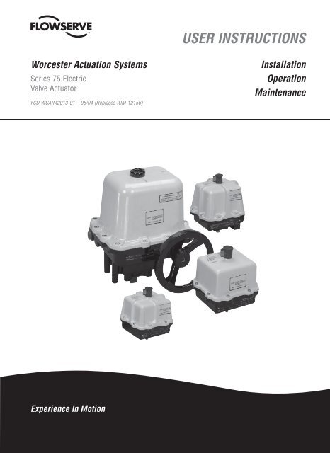
Worcester Actuation Systems Series 75 Electric Valve Actuator FCD WCAIM2013-01 - 08/04ContentsDescription 3Installation 3Electrical Installation and Adjustment 4Options and Adjustments (Factory Installed) 6Center-Off (180° Rotation) 6Feedback Potentiometers (Single, Dual) 8I-75 Interface 10Extra Limit Switches (M1 or M2) 11Mechanical Brake (10-2375 Actuators) 11Cycle Length Control (CLC Module) 11Heater and Thermostat 12Drain/Breather (V53) Option (10-2375 Actuators) 124-75 Position Indicator 12Manual Operation 13Maintenance and Troubleshooting 13Electrical Requirements 14Electrical Schematics (Series 75) 15Electrical Schematics and Wiring Diagrams for Options (Series 75) 16Parts List 182
Worcester Actuation Systems Series 75 Electric Valve Actuator FCD WCAIM2013-01 - 08/04DescriptionWorcester Actuation Systems/McCANNA Series 75 actuators arereversible electric quarter-turn valve actuators. Standard units canprovide up to 3000 in-lb of torque and have capacitor-start, capacitorrunmotors and permanently lubricated gear trains. These actuators areequipped with integral thermal overload protection (AC motors only)with automatic reset and internal adjustable limit switches. In the eventof electrical power failure, W, X and Z models feature manual overridecapabilities.c WARNING: Series 75 actuators are electromechanicaldevices subject to normal wear and tear. Actuator life isdependent upon application and environmental conditions.If applied in hazardous services, such as but not limited to,media temperature extremes, toxins, flammables, or otherservices where improper or incomplete operation couldproduce a safety hazard, it is incumbent upon the systemdesigner and the user to provide proper warning devicessuch as temperature sensors, oxygen sensors and flowsensors. At elevated temperatures the duty cycle has to bederated, consult factory. Flowserve also recommends thatthe optional auxiliary limit switches be used for monitoringand/or electrical interlock. Heater with thermostat as wellas drain/breather fitting (V53 option) are recommended forhumid environments when moisture may condense insidethe housing. Please note that weatherproof enclosures will“breathe” over time and condensation within the housingwill result.a CAUTION: For actuators with dual DC motor module, failure ofone motor may mechanically damage the gear train.a CAUTION: Flowserve recommends that all products, whichmust be stored prior to installation, be stored indoors, in anenvironment suitable for human occupancy. Do not storeproduct in areas where exposure to relative humidity above85%, acid or alkali fumes, radiation above normal background,ultraviolet light, or temperatures above 120°F or below 40°Fmay occur. Do not store within 50 feet of any source of ozone.a CAUTION: For wiring of actuator, including options, please referto wiring diagram(s) located inside of actuator cover. Wiringdiagrams are also included in this manual for reference.InstallationA. Attach mounting bracket to actuator using four (4) cap screws andlockwashers, provided in mounting kit, and tighten securely. Forsmall size top mount style valves, attach bracket such that bracketnameplate will be to side of valve.For mounting to 818/828 Series valves, insert ISO locating ring intogroove on bottom of actuator before attaching to bracket. Note:Ring can be permanently held in groove by applying Loctite to ringbefore inserting in groove.B. Attach bracket/actuator assembly to valve as follows:NOTE: If cross-line mounting of actuator is desired, note thefollowing:Mount the actuator with conduit hole perpendicular to the flow axis(centerline) of the valve and reverse the open/close decals.For diverter and three-way valves with V1 porting, and CPT valves,also see Electrical Installation and Adjustment Section, ParagraphD, for cam and limit switch adjustments to facilitate cross-linemounting operation.a CAUTION: Ball valves can trap pressurized media in thecavity. If it is necessary to remove any valve body bolts,stem nuts, or remove valve from the line, and if the valve isor has been in operation, make sure there is NO pressureto or in the valve and operate the valve one full cycle.1. Valve Models Top Mount 44 (¼"–2"), 45 (2½"–6"),51/52 (½"–10"), 151/301 (3"–6"), Top Mount 59 (¼"–4"),WK70/WK74 and H71 (½"–2"), 818/828 (2"–8"), 82/83(½"–10"), and 94 (½"–6"):NOTE: For above listed valves, it is not necessary to removeany valve body bolts or remove valve from line in order tomount actuator.a. Close valve (for valves ¼"–2", the valve is closed whenflats on valve stem are perpendicular to the line of flow; forvalves 3" and larger, where the valve stem is square, theindicator line on top of stem will be perpendicular to theline of flow or check ball position for closure).b. If any valve information is marked on stop plate or handle,it will be necessary to transfer this information to thebracket nameplate.For ¼"–2" 44 and ½"–2" WK70/WK74, ¼"–1½" 59 and½"–1½" H71 Series top mount style valves and ½"–2"51/52, ½"–1½" 82/83 Series valves with high cycle stempacking as standard, remove handle nut, lockwasher,handle, separate stop plate (if any), retaining nut and stop3fl owserve.com
Worcester Actuation Systems Series 75 Electric Valve Actuator FCD WCAIM2013-01 - 08/044pin(s). Add the two additional Belleville washers withtheir larger diameter sides touching each other. Add theself-locking nut to the stem and tighten while holding thestem flats with wrench. Tighten until Belleville washers areflat, the nut will “bottom”, and then back nut off 1 ⁄3⁄ turn.The two additional Belleville washers and the self-lockingnut are included in the mounting kit.a CAUTION: The self-locking stem nut is difficult totighten, and must fully flatten Belleville washersbefore backing off.For 2" 59, H71, 82/83, and 2½" 45, 82/83 Series valvesand valves 3" and larger with square stem, remove handleassembly (if any), retaining nut, stop and stop screws.Replace with valve stem spacer or, if valve has graphitestem packing, with two Belleville washers (except 8", 10"82/83 and 10" 51/52) and replace retaining nut. NOTE:Belleville washers are installed with larger diameterstouching each other. Using a wrench to prevent stem fromturning, tighten retaining nut until stem packing is fullycompressed or Bellevilles, if used, are fully flattened, thenback off nut 1 ⁄6⁄ turn. Excessive tightening causes highertorque and shorter seal life.NOTE: Large valves with V51 high cycle stem packingoption installed, identified by two belleville washersinstalled and handle assembly, stop and stop screwsremoved, and 818/828 Series valves do not require stemarea disassembly.For ½"–2" 94 valves, remove handle (if any). For 3"–6" 94and 2"–8" E818/E828 valves, remove handle assembly,stop, and spacer (if any). Do NOT remove gland plate orgland bolts.For 2"–8" 818/828 valves, remove handle assembly, lockingplates and hardware, and stop screw (if any). Do notremove stop plate (2"–6" sizes) or spacer (8" size).c. Center coupling on valve stem.d. Lower mounting bracket/actuator assembly over couplingand onto valve, making sure that male actuator shaftengages slot in coupling.e. Secure bracket to valve using cap screws and lockwashers,or bolts and nuts provided in mounting kit. Tightensecurely. For small size top mount style valves, bracketnameplate will be to side of valve.f. Install set screws (if any) in the coupling and tightensecurely.C. Series 75 actuator in modulating control service and interface withPC and/or computer.1. Series 75 actuators can be used for modulating control serviceoperated directly by programmable controller or computerunder specific conditions as follows:a. To achieve stable control, an actuator with a longer cycletime is recommended.b. To eliminate overheating from frequent startups, 75% or100% duty cycle actuators are required.c. To eliminate problems with interfacing, and to protectthe output circuitry of the controller, use Worcester I-75interface board.2. Alternately a controller coupled with a Series 75 actuator musthave:a. Two outputs (one to open, one to close) per actuator beingcontrolled.b. Nine amp minimum output rating.c. Buffered Output – Resistor and capacitor wired in seriesacross each triac.If a controller output does not meet these requirements,two relays (one to open, one to close) may be installedbetween controller and each actuator. Failure to observethese precautions will result in controller output damage.Electrical Installation andAdjustmenta CAUTION: It is recommended that the actuator motor not bedriven directly from the PLC output. The inrush current/backEMF can destroy the PLC output card triacs if they are not ofsufficient rating. As a minimum these should be rated 800 volt,12 amp triacs. In addition to these ratings, snubber circuitsshould be utilized to help protect the triacs. This applies to120 VAC motors only. 240 VAC motors should never be drivendirectly from a PLC output card.A. To gain access to terminal strip, it is necessary to remove theactuator cover.10-2275 (General Purpose) Loosen cover screws and lift coverfrom unit.10-2375 W, X and Z Remove declutch knob screw and lift knobfrom shaft. Remove the two cover screws from cover (the other
Worcester Actuation Systems Series 75 Electric Valve Actuator FCD WCAIM2013-01 - 08/04six screws are in an envelope and inside the cover) and lift coverfrom unit.25-3075 Z Remove indicator knob capscrew with Allen wrenchand lift knob from shaft. Remove the cover screws and lift coverfrom unit.B. Make conduit connection to NPT fitting on actuator base. Connectpower supply to actuator terminal strip as shown on electricalschematic diagram(s) located inside actuator cover and also in thismanual.The actuator should be electrically grounded in accordance withstandard procedures.For 10-2375 W, X and Z actuators, connect a CSA certified No. 18AWG green-colored grounding wire to the green-colored groundingscrew on actuator base.For 10-2275 GP actuators, connect a CSA certified No. 18 AWGgreen-colored grounding wire to terminal marked “G” on actuatorterminal strip.For 25 and 3075 Z actuators, connect a CSA certified No. 18 AWGgreen-colored grounding wire with a ring-type crimp wire connectorand a washer to the green-colored grounding screw (near terminalstrip) marked with a letter “G” on motor support plate.See table below for minimum fuse rating when overcurrent protectionis used in motor power circuit.a CAUTION: In cases where the conduit connected to theactuator may be partially or completely run underground,or through which moisture may contact energized liveparts, or where the actuator and/or conduit is exposedto temperature differences, the conduit should be sealedwithin 18" of the actuator in accordance with the NationalElectrical Code.Minimum Fuse Rating for Overcurrent ProtectionActuator Size Voltage Fuse Rating (A)10-23 120 VAC 5A25/30 120 VAC 10A10-23 240 VAC 3A25/30 240 VAC 5A10-23 12 VDC 10A10-23 24 VDC 5ANOTE: The table shows the minimum rating to prevent inrushcurrent from blowing the fuse.C. When electrical installation is complete, it is advisable to check theindexing of the actuator before replacing the cover.10-3075 (All): Move actuator to “Open” position (apply power toTerminals 1 and 3). If it does not fully open, or turns past openposition, unfasten cam of switch SW2 by loosening set screw (SW2is to the left of the shaft looking from terminal strip). Move actuatorto correct position. Adjust cam so that it just throws micro switchin this position. Tighten set screw and recheck indexing. Repeat thisprocedure for “Closed” position (apply power to Terminals 1 and4). WARNING: Do not bend switch arms when adjusting cams foractuator travel limits. Doing so will damage the cams.NOTE: If one or more of the options listed in Options and AdjustmentsSection have been installed, follow specific instructions forthose options as necessary before replacing cover.D. If actuator has been cross-line mounted and valve is a diverter orthree-way with V-1 porting or CPT valve, proceed as follows:Reset both cams to operate in next quadrant, (when looking downat cover, the “next” quadrant is 90° clockwise from standardquadrant, one quadrant closer to conduit connection). Switch #1 isthe “to close” switch, and is connected to Terminal #4. Switch #2 is“to open”, goes to Terminal #3. CPT valves must operate “clockwiseto close” viewed from top. Relocate decals to new quadrant. “Open”is 90° from conduit side, “close” is adjacent to conduit side. Ifmounted on a V-1 diverter, “open” shall expose ball port at one pipeend, “closed” shall expose ball port at the opposite pipe end.E. Replace actuator cover.NOTE: For W and Z models, make sure flange gasket/seal isproperly installed. Tighten all cap screws securely.For X and Z Models Only:After placing the cover on the actuator, tighten the cover bolts in acrisscross fashion to a torque of 70-80 in-lbs.A feeler gage, being 1 ⁄8⁄ " to ½" wide and 0.0015" thick, shall be usedto check the clearance between the base and cover flange.This feeler gage shall not penetrate the base/cover flange gap anymore than 1 ⁄8⁄ ".10-2375 W, X and Z: Replace declutching knob, taking care thatknob set screw engages milled flat on clutch shaft and indicatesproper position on labeled cover.25-3075 Z: Replace indicator knob in its proper position to givecorrect indication. Tighten indicator’s cap screw securely.5fl owserve.com
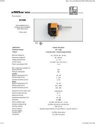
Worcester Actuation Systems Series 75 Electric Valve Actuator FCD WCAIM2013-01 - 08/04Options and Adjustments(Factory Installed)NOTE: For wiring of the following options, please refer to the appropriateoption wiring diagram(s) located inside actuator cover orincluded with option kit. Wiring diagrams for most options are alsoincluded in this manual for reference.All wiring to terminal strip should be inserted only to mid-point ofterminal strip.For some options with AC actuators, multiple wires are going to terminal1. A short white wire is provided and connected to terminal 1, thenspliced to the other white wires (common) using a closed end splice.A. Center-Off (180° Rotation)1. Readjustment of “Center-Off” Cams (if necessary):a. With the cover removed and the actuator placed with theterminal strip facing the operator, switches 1 and 3 are tothe right and switches 2 and 4 are to the left of the mainshaft.b. There are four cams and two spacers on the shaft. Per thedrawing on the following page, these cams are numbered1 through 4, from bottom to top. (See proper drawing forapproximate location and correct orientation of the centeroffcams.)c. Using the manual override (see page 12) as necessary, setthe actuator shaft to a “center-off” location.Set cam #3 such that hook of switch 3 lever arm has justdropped off the cam. Tighten cam screw without movingcam.a CAUTION: Do not bend the limit switch lever arm.Set cam #4 such that hook of switch 4 lever arm willmatch the arch of cam #4. Tighten cam screw withoutmoving cam.a CAUTION: Do not bend the limit switch lever arm.Release manual override.d. Power the actuator to the full clockwise (CW) limit, to the0° reference position. Check position of ball and valve stemto verify that valve is in the true 0° position, as required bythe application.e. Repeat the above step for the 180° or full CCW position.Verify that the driven device is in the required position.f. Apply power to terminals 1 and 7 for AC (+ to 7 and - to 8for DC) to verify proper operation of center-off switches.With the actuator shaft positioned at the 180° position,power applied to terminals 1 and 7 for AC (+ to 7 and - to8 for DC) moves the actuator shaft clockwise (CW) to thecenter-off position.With the actuator shaft at the full clockwise position, 0degrees, apply power to terminals 1 and 7 for AC (+ to 7and - to 8 for DC). The actuator shaft should move counterclockwiseCCW to the center-off position.180° Center-Off Actuator Series 75W, X, And Z ShownTypical View Showing Location of Center-Off Camsand Limits Switches Set Up at the Center-Off PositionStandard 90° ActuatorSeries 75W, X, and Z ShownView “A”6
Worcester Actuation Systems Series 75 Electric Valve Actuator FCD WCAIM2013-01 - 08/04SPECIAL NOTE: If during any of these checks, the actuatorshaft stops other than at the required positions, a readjustmentof the center-off cams is needed. At no time shallboth center-off switches be activated by their cams at thesame time. The N.O. contacts on both center-off switchesare typically closed. The center-off switch levers must betripped by their center-off cams at different times.No oscillation or hunting of the actuator output shaftshould occur.If the above problems are noted, simply readjust thecenter-off cams as noted in Step f.Therefore, the center-off cams should be set as close to the90 degree position as possible, yet the cam/switch actuationfor each switch is never at the identical position.If the center-off switches are set to actuate at a closeangular differential, the actuator shaft may oscillate, or notoperate. Loosen one cam and move this cam to increasethe actuation differential between each of the center-offswitches.If the center-off switches are set to actuate at a wideangular differential, the actuator will not stop at a truecenter-off position. Adjust one or both cams to decreasethe angular differential between each of these switches.120 VAC ShownSwitch configuration is as above (when viewed from theterminal strip side of the actuator.Actuator shown at 0° position (fully CW).g. As a final check, alternately apply power to terminals 1 and4, 1 and 3, and 1 and 7 for AC, (+ to the 1 and - to the 4;- to 1 and + to 3; - to 8 and + to 7 for DC).10-23 Size 75 ActuatorsItem Description1 Circuit Board Sub-Assembly2 Insulating Board3 Bracket-Right (Long)4 Grommet-Rubber5 Mounting Screws (Cir. Board)6 Washer-Nylon7 Bracket-Left (Short)8 Mounting Screws (Bracket)9 Spacer (Bracket)25-30 Size 75 ActuatorsItem Description1 Circuit Board Sub-Assembly2 Insulating Board3 Circuit Board Bracket4 Mounting Screw (Bracket)5 Grommet-rubber6 Washer-Nylon7 Mounting Screw (Cir. Board)8 Capacitor (Round Or Rectangular)9 Capacitor Tie (See Note)10 Capacitor Bracket And Screw (See Note)Note: Not Used For Round Type Capacitor With Threaded Lug.fl owserve.com7
Worcester Actuation Systems Series 75 Electric Valve Actuator FCD WCAIM2013-01 - 08/04Cam settings are as follows:Switch 1 opens at 0°. Controls first divert position.Switch 2 opens at 180°. Controls secont divert position.Switch 3 opens at 89°. Controls center-off position fromfirst divert position.Switch 4 opens at 91°. Controls center-off position fromsecond divert position.NOTE: Switches 1 and 2 and Cams 1 and 2 are standard.Switches 3 and 4 and Cams 3 and 4 are center-off type.Use cam spacer as needed to line up cam and switch.B. Feedback Potentiometers (Single, Dual)The potentiometer, as part of the Series 75 Actuator, is used toobtain feedback representing the actuator’s position. It requires apower supply, which may be furnished by the end user and/or byoptional devices such as a 4-75 (4-20 mA) Position Indicator orAF17 Positioner.A Dual Potentiometer is used with the DFP17, AF17 Positionersor 4-75 Position Indicator when remote resistance indicationis required.The Dual Potentiometer is required when both AF17 or DFC 17 and4-20 mA position output options are to be used together, one potfor each device.Each pot can serve only one function. Remote resistance monitoringand an AF17, for example, cannot share a pot.1. Adjusting Potentiometer:NOTES: Potentiometers are adjusted at factory. If readjusting isnecessary, follow instructions below.Voltage limit of single pot or “B” pot of dual potentiometer is 30volts maximum.a. 10-3075 Actuator:If not already installed, place the large face gear (12) overthe actuator shaft with the gear teeth down and secure withsnap ring (16) provided.NOTE: The face gear utilizes a friction fit to the shaft. Forbest results, wipe off any lubricant that may be on the shaftbefore sliding on the face gear.a CAUTION: Do not overstretch the snap ring, usethe minimum opening to allow snap ring to slipover the gear.b. Adjust the potentiometer spur gear (8) until there is approximately1 ⁄16⁄ " engagement with the large face gear. Tighten thespur gear set screw (9). If necessary, you can slightly bendpotentiometer bracket to get proper engagement.c. Rotate the face gear back and forth to ensure smooth andeasy operation of the potentiometer.d. Important: FOR 90° VALVES: With the actuator in theOPEN (full CCW) or CLOSED (full CW) position and poweroff, rotate the face gear, thus turning the potentiometershaft until the resistance between the white/black lead(terminal 11) and the green lead (terminal 10) or the white/black lead (terminal 11) and the purple lead (terminal 12respectively, as measured by an ohmmeter, is between 80ohms and 90 ohms. (Refer to instruction sheets of optionsthat may have different pot lead locations and adjustments,e.g., AF17 Positioner.)NOTE: It is not necessary to loosen or remove face gearsnap ring to rotate gear.e. Power the actuator to the opposite position from whereresistance was measured.f. At this position, with power off, measure the resistance atthe same terminals as stated above. The resistance readingshould be greater than 700 ohms. If not, then poweractuator back to original position and adjust pot again, ifnecessary, as stated in paragraph d. above. If unsuccessfulin getting proper resistance readings, pot is defective andshould be replaced.The feedback potentiometer is now adjusted for use in the75 actuator.IMPORTANT: The feedback potentiometer is calibratedfor only one 90° quadrant of valve operation. If the outputshaft is repositioned to another 90° quadrant or if theoutput shaft is rotated on a multiple of 360° from itsoriginal position, the feedback potentiometer will no longerbe in calibration and must be recalibrated.8
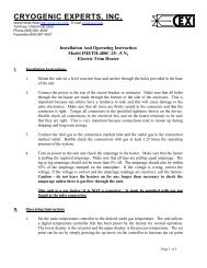
Worcester Actuation Systems Series 75 Electric Valve Actuator FCD WCAIM2013-01 - 08/04Feedback Potentiometers10-2375 Plan View View A-A25/3075 Plan View View B-BItem Description1 Limit Switches2 Motor Module3 Motor Module Mounting Screws (2)4 Terminal Strip5 Actuator Shaft6 Potentiometer7 Potentiometer Bracket8 Spur Gear9 Spur Gear Set ScrewItem Description10 Potentiometer Leads11 Potentiometer Shaft12 Face Gear13 Potentiometer Bracket14 Mounting Screws (2)15 Motor Support Plate16 Snap Ring17 Lockwashers (2)18 NutIllustrations show single potentiometer only.9fl owserve.com
Worcester Actuation Systems Series 75 Electric Valve Actuator FCD WCAIM2013-01 - 08/0425 and 3075Depending on the control input used there are several optionsof the I-75 Interface:5V for 5 VDC input, XV for 12 VDC input, XX for 24 VDC input,15 for 120 VAC input.These options are identified by the nameplate on the circuitboard.2. Indication and Repair:10-2375LED Indicators – Light emitting diodes marked LD1, LD2 arein input circuits and indicating what particular input is on. Left,LD2, LED indicates that CCW, open, signal is on. Right, LD1,LED indicates that CW, close, signal is on.If a malfunction occurs, look for the following:If particular input is energized and corresponding LED light isnot on, check for component damage or other continuity disruptionin corresponding CCW and/or CW input circuit. If everythingappears to be OK, replace matching opto-coupler U2 or U1.10Typical Top ViewItemC. I-75 Interface1. Description:Description1 Extra Switch2 #4-40 Screws (2)3 Extra Cam4 Set Screw (1)5 Spacers (25/3075 Only)6 Spacers (two per Switch)7 InsulatorThe I-75 Interface is designed to be used and mounted in theSeries 75 Actuator as one of many standard options. Functionof the I-75 Interface is to allow the Series 75 Actuatorto be powered by a 120 or 240 VAC power supply, operateddirectly by any programmable controller, microprocessor,and/or computer regardless of output rating of these devices.Input circuit is OK. LED is lighted and actuator is not running.If components and continuity in corresponding power circuitare all right, then failed component is triac Q2 or Q1 dependingwhich way the actuator doesn’t run, CCW or CW.If the actuator doesn’t run in either direction, it is likely thatthe actuator is defective. To check this, remove the red andblack leads from terminals 3 and 4 of the actuator (comingfrom Interface board) and the AC line connections fromterminals 1 and 2. Tape these leads. Using a test cable, applypower to actuator terminals 1 and 3. The 120 VAC actuatoronly (see Note) should rotate CCW until stopped by the CCWlimit switch. Then apply power to terminals 1 and 4 to checkCW 120 VAC actuator and the CW limit switch. If the actuatordoes not operate, check 120 VAC associated wiring, terminalstrip, the limit switches, motor, and capacitor. Check switchcontinuity. Check for an open motor winding, and check for ashorted capacitor. If the problem in the actuator still cannot bedetermined, return the unit for service. If the actuator functionsproperly, the problem is in interface board.Request an RMA (Return Material Authorization) numberfrom the service department, replace the defective board, andreturn it to the factory with proper description of problem andapplication.NOTE: The limit switches for the 240 VAC I-75 actuator do notcontrol the motor circuit, they control input circuit only. Whenapplying power to terminals 1 and 3, and 1 and 4 to checkCCW, CW rotations, do this momentarily so that you do notoverride 0-90° quadrant.
Worcester Actuation Systems Series 75 Electric Valve Actuator FCD WCAIM2013-01 - 08/04D. Extra Limit Switches (M1 or M2)1. Setting:10-23 75 Assembly ShownNOTE: Switches and cams are set at factory. If resetting isnecessary, use the following procedure:a. Bring actuator into position desired to actuate extra switch.Turn extra cam in direction of normal travel until switch justthrows.b. Advance cam in same direction by 1–3° and secure cam bytightening the set screw (4).For M2, a fourth switch (not shown) is added over SW2.The fourth cam (not shown) is positioned so that camset screw faces terminal strip when cam is in contactwith limit switch to give desired function. Cam lobe mustapproach switch lever from lever pivot end and not fromfree end—see Typical Top View on page 9. Follow settinginstructions on last page.E. Mechanical Brake (10-2375 Actuators)NOTE: Mechanical brake should require no adjusting.1. Testing and Troubleshooting:a. Energize actuator for rotation in both open and closeddirections. At the rated actuator voltage, the brake coil isenergized and moves the plunger to release brake arm.Clearance of .020” to .030” must exist between the brakearm and the brake disc when power is applied to theactuator.b. If the brake arm is too close to the brake disc, realign thecoil housing so that coil plunger can move further towardthe center of the actuator, permitting more movement ofthe brake arm.c. Plunger chattering indicates a low supply voltage. Ifactuator voltage is at the rated conditions, realign coilhousing so that coil moves away from the center of theactuator to reduce plunger movement.d. All coil adjustment is done in small increments of .015inches or less.e. Additional adjustment may be done by moving mountingplate toward/away from actuator shaft.f. Once proper operation of the brake is verified replaceactuator cover.Item Qty Description1 1 Circuit Board2 1 Mounting Plate3 5 Spacers (.06”)4 2 Spacers (.25”)5 2 Flat Head Screws6 3 Head Screws7 3 Nuts8 1 Insulator9 3 Cable Ties (Not Shown)10 1 Potentiometer Kit (Not Shown)F. Cycle Length Control (CLC Module)a CAUTION: CLC module must be used with proper line voltage.Control of the actuator’s cycle time is achieved by breaking up thepower applied to the actuator into a series of pulses. The length oftime a power pulse is applied is controlled by the “ON” adjustablecontrol. The interval between pulses is controlled by the “OFF”adjustable control.To adjust, start with both controls at midpoint. To reduce cycle timeon 120 VAC units, turn “ON” control in CW direction and “OFF”control in CCW direction. To increase cycle time turn “ON” controlin CCW direction and “OFF” in CW direction. To reduce cycle timeon 240 VAC units, turn “ON” control in CCW direction and “OFF”control in CW direction. To increase cycle time turn “ON” control inCW direction and “OFF” in CCW direction.IMPORTANT: If “ON” time adjustable control is at minimum and/or“OFF” time adjustable control is at maximum, the actuator will notrotate. The minimum “ON” pulse must allow the actuator to move aclosed valve out of its seat. Verify proper CLC operation by openinga fully closed valve.fl owserve.com11
Worcester Actuation Systems Series 75 Electric Valve Actuator FCD WCAIM2013-01 - 08/04Electrical RequirementsThe following table represents approximate current draw (at rated stall torques) in amp at various voltages for each motor.Actual values depend on several variables. For exact values, test the unit at a particular load.Actuator SizeSuffix Code Duty Cycle Voltage 10 12 15 20 22 23 25 30Blank 20% 120 AC — — 0.7 — — — — —Blank 25% 120 AC 0.7 0.7 — 1.5 1.5 — 2.7 3.52 10% 120 AC 1.5 1.5 — 2.9 2.9 — — —4 75% 120 AC 0.3 0.3 — 0.7 0.7 0.7 2.2 2.25 100% 120 AC 0.25 0.25 — 0.5 — — — —Blank 25% 240 AC 0.4 0.4 — 0.9 0.9 — 1.3 1.42 10% 240 AC 0.6 0.6 — 1.3 1.3 — — —4 75% 240 AC 0.15 0.15 — 0.3 0.3 0.3 1.2 1.25 100% 240 AC — — — — — — — —Blank 25% 12 DC 1.4 1.2 — 5 4.2 — — —4 75% 12 DC 0.5 0.5 — 1.6 1.5 2 — —Blank 25% 24 DC 0.7 0.6 — 2.5 2.1 — — —4 75% 24 DC 0.25 0.25 — 0.8 0.75 1 — —Cycle Time (sec.)Suffix Code 10 12 15 20 22 23 25 30Blank 5 8 5 5 8 — 10 152 2.5 4 — 2.5 4 — — —4 17, 15 27, 25 — 17, 15 27, 25 25 15 235 17 27 — 27 — — — —If a heater is used on 12 or 24 VDC actuators, increase the locked rotor currentsshown above by the following values (This applies to DC voltages only):Locked Rotor Currents12 VDC 24 VDCHeater 1.3 amp 0.7 amp14
Worcester Actuation Systems Series 75 Electric Valve Actuator FCD WCAIM2013-01 - 08/04Electrical Schematics (Series 75)(Actuator shown in counter-clockwise extreme of travel, or “open” position.)NOTE: DC wiring diagram shown is for size 10, 20 and 23 actuators. For 12 and 22 sizes, the red/black motor leads are reversed.For G.P. Actuators only, terminal 6 is used for ground connection and L2 should be wired directly to N.O. Terminal of SW-2.ACDCIMPORTANT: each actuator should be electrically powered through its ownindividual switch to isolate the unused winding.Each motor has a “thermal protector” as shown by wiring of MB 75 option indiagram.See table on page 5 for minimum fuse rating when overcurrent protection is usedin motor power circuit.15fl owserve.com
Worcester Actuation Systems Series 75 Electric Valve Actuator FCD WCAIM2013-01 - 08/04Electrical Schematics and Wiring Diagrams for Options (Series 75)(For installation of options, refer to installation instructions and wiring diagram(s) contained in respective kit.)NOTE: DC center-off wiring diagram as shown on page 17 is for size 12 and 22 actuators.For 10, 20 and 23 sizes, the red/black motor leads are reversed.General Schematic10-30 C 75 120A/240A C 10-30 C 75 120A/240A O 10-30 C 75 120A/240AWiring for 10-30 P/D 75 Feedback Pot OptionWiring for 10-30 H75 Heater/ Thermostat OptionWiring for 10-30 75 M1 Option (One Extra Limit Switch)Wiring for 10-30 75 M2 Option (Two Extra Limit Switches)161 2 3 4 5 6 7BROWN/WHITECOMMONCOMM. SW3GRAY8 9NORM. CLOSEDN.C. SW3ORANGENORM. OPENN.O. SW310 1112EXTERNAL INTERNAL1 2 3 4 5 6 7BROWN/WHITECOMMONCOMM. SW3GRAYN.C. SW3ORANGE8 9NORM. CLOSEDNORM. OPENN.O. SW3RED10COMMONCOMM. SW4ORANGE11NORM. CLOSEDN.C. SW4BLUE12NORM. OPENN.O. SW4M1INTERNALEXTERNALM1M2
Worcester Actuation Systems Series 75 Electric Valve Actuator FCD WCAIM2013-01 - 08/04Series 75 AC Electric Actuator with Center-Off (D3) OptionSeries 75 DC Electric Actuator with Center-Off (D3) OptionWiring of I-75 240 VAC InterfaceWiring of I-75 120 VAC InterfaceWiring of 4-75 120 VAC Position Indicator17fl owserve.com
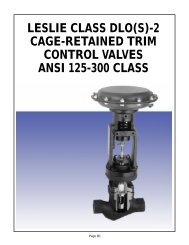
Worcester Actuation Systems Series 75 Electric Valve Actuator FCD WCAIM2013-01 - 08/04Parts ListSizes 10-23Note: Series 75 W is shown. Series 75 general purpose, X and Z units have different bases and covers.18Item Qty Description Material1 1 Base Aluminum Casting2 1 Cover Aluminum Casting3 1 Base Plate Zinc Casting4 1 Motor Module Zinc Casting5 1 Output Shaft Steel6 2 Gear Drive Pin Steel7 1 Bull Gear Steel8 1 Capacitor(Round or Rectangular Type)9 2 Switch Insulator (not shown) NylonPhenolic Encapsulated10 1 Terminal Strip Polyethylene Based Material11 2 Limit Switch Phenolic Encapsulated12 2 Limit Switch Cam Zinc Casting13 1/Cam Cam Set Screw Steel14 4 Limit Switch Screw Steel15 6 Base Plate Screw Steel16 8 Hex Screw (W, X, Z) Stainless SteelItem Qty Description Material16 4 Hex Screw (GP) Steel17 1 Position Indicator (W, X, Z) Lexan18 1 Indicator Set Screw (W, X, Z) Steel19 1 Seal (W, X, Z) Reinforced Rubber20 1 Gasket (W only) Neoprene20 1 Flange Seal (Z only) Buna N21 1 Bearing Bronze22 1 Seal Reinforced Nitrile23 4 Screw Steel24 4 Lock Washer Steel25 1 Conduit Plug Polyethylene26 1 Cap. Tie (for Rect. Cap. only) Plastic27 1 Bearing (W,X,Z) Bronze28 1 Roller Bearing (size 23 only) Steel29 1 Bearing, Base Plate Nylon30 1 “O” Ring (W,X,Z) Buna
Worcester Actuation Systems Series 75 Electric Valve Actuator FCD WCAIM2013-01 - 08/04Sizes 25, 30Item Qty Description Material1 1 Base Aluminum2 1 Cover Aluminum3 1 Gear Train Support Aluminum4 1 Motor5 1 Output Gear Steel Casting6 2 Planet Gear Hardened Steel7 1 Planetary Gear Ductile Iron8 1 Worm Gear Steel9 1 Sensing Shaft Steel10 2 Pin, Spring Steel11 2 Shaft Hardened Steel12 2 Bushing Bronze13 2 Thrust Washer Steel14 1 Pin, Spring Steel15 4 Belleville Washer Steel16 1 Nut Steel17 2 Seal Rubber, Steel18 1 Manual Override Shaft Steel19 1 Pin, Cotter Steel20 1 Pin, Spring Steel21 1 Handwheel, Manual Override Aluminum22 1 Thrust Washer Steel23 1 Tru-arc Ring Steel24 1 Seal Rubber, Steel25 1 Sun Gear Steel26 1 Bushing BronzeItem Qty Description Material27 4 Cap Screw Steel28 4 L Washer Steel29 1 Capacitor(Round or Rectangular type)30 1 Input Gear Steel31 1 Nut Steel32 1 Cap Screw Steel33 1 Position Indicator Aluminum34 1 Bushing Bronze35 1 Motor Support Plate Aluminum36 1 Gear, Pinion Steel37 2 Set Screw SteelPhenolic Encapsulated38 1 Terminal Strip Polyethylene Based Material39 2 Limit Switch Cam Zinc Casting40 1/Cam Cam Set Screw Steel41 1 Fan Plastic42 2 Limit Switches Phenolic Encapsulated43 1 “O” Ring Buna44 9 Cap Screw Steel45 9 Lock Washer Steel46 12 Cap Screw Steel47 1 Sensing Shaft Ret. Ring Steel48 1 Conduit Plug Polyethylene49 1 Cap. Bracket(for Rect Cap. only)51 1 Cap. Bracket Screw(for Rect. Cap.)SteelSteelfl owserve.com19
United StatesFlowserve Corp.Flow ControlFlowserve Worcester ActuationSystems5114 Woodall RoadP.O. Box 11318Lynchburg, VA 24506-1318 USAPhone: 1 434 528 4400Fax: 1 434 845 9736FCD WCAIM2013-01 Printed in USA. (Replaces IOM-12156)To find your local Flowserve representative:For more information about Flowserve Corporation, visitwww.flowserve.com or call USA 1 800 225 6989Flowserve Corporation has established industry leadership in the design and manufacture of its products. When properly selected, this Flowserve product is designed to perform its intendedfunction safely during its useful life. However, the purchaser or user of Flowserve products should be aware that Flowserve products might be used in numerous applications under a widevariety of industrial service conditions. Although Flowserve can (and often does) provide general guidelines, it cannot provide specific data and warnings for all possible applications. The purchaser/usermust therefore assume the ultimate responsibility for the proper sizing and selection, installation, operation, and maintenance of Flowserve products. The purchaser/user shouldread and understand the Installation Operation Maintenance (IOM) instructions included with the product, and train its employees and contractors in the safe use of Flowserve products inconnection with the specific application.While the information and specifications contained in this literature are believed to be accurate, they are supplied for informative purposes only and should not be considered certified or asa guarantee of satisfactory results by reliance thereon. Nothing contained herein is to be construed as a warranty or guarantee, express or implied, regarding any matter with respect to thisproduct. Because Flowserve is continually improving and upgrading its product design, the specifications, dimensions and information contained herein are subject to change without notice.Should any question arise concerning these provisions, the purchaser/user should contact Flowserve Corporation at any one of its worldwide operations or offices.© 2004 Flowserve Corporation, Irving, Texas, USA. Flowserve is a registered trademark of Flowserve Corporation.fl owserve.com