7.5 TON - 12.5 TON PACKAGE GAS SERIES CPG SERIES - Goodman
7.5 TON - 12.5 TON PACKAGE GAS SERIES CPG SERIES - Goodman
7.5 TON - 12.5 TON PACKAGE GAS SERIES CPG SERIES - Goodman

Create successful ePaper yourself
Turn your PDF publications into a flip-book with our unique Google optimized e-Paper software.
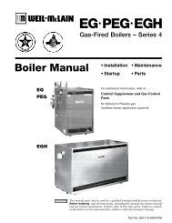
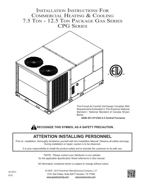
INSTALLATION INSTRUCTIONS FOR<br />
COMMERCIAL HEATING & COOLING<br />
<strong>7.5</strong> <strong>TON</strong> - <strong>12.5</strong> <strong>TON</strong> <strong>PACKAGE</strong> <strong>GAS</strong> <strong>SERIES</strong><br />
<strong>CPG</strong> <strong>SERIES</strong><br />
®<br />
C<br />
US<br />
This Forced Air Central Unit Design Complies With<br />
Requirements Embodied in The American National<br />
Standard / National Standard of Canada Shown<br />
Below.<br />
ANSI Z21.47•CSA-2.3 Central Furnaces<br />
RECOGNIZE THIS SYMBOL AS A SAFETY PRECAUTION.<br />
ATTENTION INSTALLING PERSONNEL<br />
Prior to installation, thoroughly familiarize yourself with this Installation Manual. Observe all safety warnings.<br />
During installation or repair, caution is to be observed.<br />
It is your responsibility to install the product safely and to educate the customer on its safe use.<br />
*NOTE: Please contact your distributor or our website<br />
for the applicable Specification Sheet referred to in this manual.<br />
All information contained herein is subject to change without notice.<br />
IO-337J<br />
6/10<br />
© 2008 - 2010 <strong>Goodman</strong> Manufacturing Company, L.P.<br />
5151 San Felipe, Suite 500 ◊ Houston, TX 77056<br />
www.goodmanmfg.com www.amana-hac.com
Index<br />
Replacement Parts ........................................................ 2<br />
Safety Instructions ........................................................ 2<br />
General Information ...................................................... 3<br />
Unit Location ................................................................. 4<br />
Clearances ..................................................................... 6<br />
Roof Curb Post-Installation .......................................... 6<br />
Checks ........................................................................... 6<br />
Roof Top Duct Connections ......................................... 6<br />
Rigging Details .............................................................. 7<br />
Electrical Wiring ............................................................ 8<br />
Gas Supply Piping ....................................................... 10<br />
Propane Gas Installations .......................................... 12<br />
Circulating Air and Filters ........................................... 13<br />
Venting ......................................................................... 13<br />
Condensate Drain Connection ................................... 13<br />
Startup, Adjustments, and Checks ............................ 13<br />
Normal Sequence Of Operation ................................. 19<br />
Troubleshooting .......................................................... 20<br />
Input Rating ................................................................. 21<br />
Air flow Adjustments................................................... 21<br />
Motor Sheave Adjustments ........................................ 21<br />
Maintenance ................................................................ 22<br />
Appendix A Blower Performance Data ...................... 24<br />
Belt Drive - STANDARD hORIZONTAL ....................... 24<br />
Appendix A Blower Performance Data ...................... 25<br />
Belt Drive - STANDARD dOWN sHOT ........................ 25<br />
Belt Drive - HIGH STATIC (“AA” Models Only) .......... 26<br />
Appendix B Electrical Data ......................................... 27<br />
Appendix C Unit Dimensions ..................................... 28<br />
Wiring Diagrams .......................................................... 29<br />
ORDERING PARTS<br />
REPLACEMENT PARTS<br />
When reporting shortages or damages, or ordering repair<br />
parts, give the complete unit model and serial numbers<br />
as stamped on the unit’s nameplate.<br />
Replacement parts for this appliance are available<br />
through your contractor or local distributor. For the<br />
location of your nearest distributor, consult the white<br />
business pages, the yellow page section of the local<br />
telephone book or contact:<br />
CONSUMER AFFAIRS<br />
GOODMAN MANUFACTURING COMPANY, L.P.<br />
7401 SECURITY WAY<br />
HOUS<strong>TON</strong>, TEXAS 77040<br />
877-254-4729<br />
TO THE INSTALLER<br />
SAFETY INSTRUCTIONS<br />
Before installing this unit, please read this manual to<br />
familiarize yourself on the specific items which must be<br />
adhered to, including maximum external static pressure<br />
to unit, air temperature rise, minimum or maximum CFM<br />
and motor speed connections.<br />
Keep this literature in a safe place for future reference.<br />
WARNING<br />
IF THE INFORMATION IN THESE INSTRUCTIONS IS NOT FOLLOWED<br />
EXACTLY, A FIRE OR EXPLOSION MAY RESULT CAUSING PROPERTY<br />
DAMAGE, PERSONAL INJURY OR LOSS OF LIFE.<br />
DO NOT STORE OR USE <strong>GAS</strong>OLINE OR OTHER FLAMMABLE VAPORS AND<br />
LIQUIDS IN THE VICINITY OF THIS OR ANY OTHER APPLIANCE.<br />
WHAT TO DO IF YOU SMELL <strong>GAS</strong>:<br />
DO NOT TRY TO LIGHT ANY APPLIANCE.<br />
DO NOT TOUCH ANY ELECTRICAL SWITCH; DO NOT USE ANY PHONE<br />
IN YOUR BUILDING.<br />
IMMEDIATELY CALL YOUR <strong>GAS</strong> SUPPLIER FROM A NEIGHBOR’S<br />
PHONE. FOLLOW THE <strong>GAS</strong> SUPPLIER’S INSTRUCTIONS.<br />
IF YOU CANNOT REACH YOUR <strong>GAS</strong> SUPPLIER, CALL THE FIRE<br />
DEPARTMENT.<br />
INSTALLATION AND SERVICE MUST BE PERFORMED BY A QUALIFIED<br />
INSTALLER, SERVICE AGENCY OR THE <strong>GAS</strong> SUPPLIER.<br />
WARNING<br />
WARNING<br />
SHOULD OVERHEATING OCCUR OR THE <strong>GAS</strong> SUPPLY FAIL TO SHUT OFF,<br />
TURN OFF THE MANUAL <strong>GAS</strong> SHUTOFF VALVE EXTERNAL TO THE<br />
FURNACE BEFORE TURNING OFF THE ELECTRICAL SUPPLY.<br />
DO NOT CONNECT TO OR USE ANY DEVICE THAT IS NOT DESIGN<br />
CERTIFIED BY GOODMAN FOR USE WITH THIS UNIT. SERIOUS PROPERTY<br />
DAMAGE, PERSONAL INJURY, REDUCED UNIT PERFORMANCE AND/OR<br />
HAZARDOUS CONDITIONS MAY RESULT FROM THE USE OF SUCH NON‐<br />
APPROVED DEVICES.<br />
CAUTION<br />
SHEET METAL PARTS, SCREWS, CLIPS AND SIMILAR ITEMS INHERENTLY<br />
HAVE SHARP EDGES, AND IT IS NECESSARY THAT THE INSTALLER AND<br />
SERVICE PERSONNEL EXERCISE CAUTION.<br />
2
WARNING<br />
THIS PRODUCT CONTAINS OR PRODUCES A CHEMICAL OR CHEMICALS<br />
WHICH MAY CAUSE SERIOUS ILLNESS OR DEATH AND WHICH ARE<br />
KNOWN TO THE STATE OF CALIFORNIA TO CAUSE CANCER, BIRTH<br />
DEFECTS OR OTHER REPRODUCTIVE HARM.<br />
WARNING<br />
TO AVOID PROPERTY DAMAGE, PERSONAL INJURY OR DEATH, DO NOT<br />
USE THIS UNIT IF ANY PART HAS BEEN UNDER WATER. IMMEDIATELY<br />
CALL A QUALIFIED SERVICE TECHNICIAN TO INSPECT THE FURNACE AND<br />
TO REPLACE ANY PART OF THE CONTROL SYSTEM AND ANY <strong>GAS</strong><br />
CONTROL HAVING BEEN UNDER WATER.<br />
WARNING<br />
THIS UNIT MUST NOT BE USED AS A “CONSTRUCTION HEATER” DURING<br />
THE FINISHING PHASES OF CONSTRUCTION ON A NEW STRUCTURE. THIS<br />
TYPE OF USE MAY RESULT IN PREMATURE FAILURE OF THE UNIT DUE TO<br />
EXTREMELY LOW RETURN AIR TEMPERATURES AND EXPOSURE TO<br />
CORROSIVE OR VERY DIRTY ATMOSPHERES.<br />
HIGH VOLTAGE !<br />
WARNING<br />
DISCONNECT ALL POWER BEFORE SERVICING OR<br />
INSTALLING THIS UNIT. MULTIPLE POWER SOURCES MAY<br />
BE PRESENT. FAILURE TO DO SO MAY CAUSE PROPERTY<br />
DAMAGE, PERSONAL INJURY OR DEATH.<br />
WARNING<br />
TO PREVENT THE RISK OF PROPERTY DAMAGE, PERSONAL INJURY OR<br />
DEATH, DO NOT STORE COMBUSTIBLE MATERIALS OR USE <strong>GAS</strong>OLINE OR<br />
OTHER FLAMMABLE LIQUIDS OR VAPORS IN THE VICINITY OF THIS<br />
APPLIANCE.<br />
WARNING<br />
ONLY INDIVIDUALS MEETING (AT A MINIMUM) THE REQUIREMENTS<br />
OF AN “ENTRY LEVEL TECHNICIAN” AS SPECIFIED BY THE AIR<br />
CONDITIONING, HEATING, AND REFRIGERATION INSTITUTE (AHRI)<br />
MAY USE THIS INFORMATION. ATTEMPTING TO INSTALL OR REPAIR<br />
THIS UNIT WITHOUT SUCH BACKGROUND MAY RESULT IN PRODUCT<br />
DAMAGE, PERSONAL INJURY OR DEATH.<br />
WARNING<br />
CARBON MONOXIDE POISONING<br />
HAZARD<br />
FAILURE TO KEEP THIS COMPARTMENT CLOSED<br />
EXCEPT WHEN SERVICING COULD RESULT IN<br />
CARBON MONOXIDE POISONING OR DEATH.<br />
THIS COMPARMENT MUST BE CLOSED EXCEPT<br />
WHEN SERVICING<br />
AVERTISSEMENT<br />
RISQUE D'EMPOISONNEMENT AU<br />
MONOXYDE DE CARBONE<br />
SI CE COMPARTMENT N'EST PAS FERME EN<br />
TOUT TEMPS, SAUF EN CAS DE REPARATION, IL Y<br />
A RISQUE D'EMPOISONNEMENT OU MONOXYDE<br />
DE CARBONE OU DE MORT.<br />
CE COMPARTIMENT DOIT ETRE FERME SAUF AU<br />
MOMENT DE L'ENTRETIEN.<br />
ADVERTENCIA<br />
PELIGRO MONOXIDO DE CARBONO<br />
TOXICO<br />
EL FRACASO DE NO MANTENER<br />
COMPARTIMIENTO CERRADO MENOS DURANTE,<br />
ATENDER, PODRIA TENER COMO RESULTADO<br />
ENVENENAR DE MONOXIDO DE CARBONO O<br />
MUERTE.<br />
ESTE COMPARTIMIENTO DEBE CERRADO MENOS<br />
-<br />
AL ATENDER<br />
0140L00106<br />
GENERAL INFORMATION<br />
WARNING<br />
TO PREVENT PROPERTY DAMAGE, PERSONAL INJURY OR DEATH DUE TO<br />
FIRE, EXPLOSIONS, SMOKE, SOOT, CONDENSATION, ELECTRIC SHOCK OR<br />
CARBON MONOXIDE, THIS UNIT MUST BE PROPERLY INSTALLED,<br />
REPAIRED, OPERATED AND MAINTAINED.<br />
This unit is approved for outdoor installation ONLY. To<br />
assure that your unit operates safely and efficiently, it must<br />
be installed, operated, and maintained in accordance with<br />
these installation and operating instructions, all local building<br />
codes and ordinances, or in their absence, with the latest<br />
edition of the National Fuel Gas Code NFPA54/ANSI Z223.1<br />
and National Standard of Canada CAN/CSA B149 Installation<br />
Codes.<br />
The heating and cooling capacities of the unit should be<br />
greater than or equal to the design heating and cooling loads<br />
of the area to be conditioned. The loads should be calculated<br />
by an approved method or in accordance with ASHRAE Guide<br />
or Manual J - Load Calculations published by the Air Conditioning<br />
Contractors of America.<br />
Obtain from:<br />
American National Standards Institute<br />
1430 Broadway<br />
New York, NY 10018<br />
3
System design and installation should also, where applicable,<br />
follow information presented in accepted industry guides such<br />
as the ASHRAE Handbooks. The manufacturer assumes no<br />
responsibility for equipment installed in violation of any code<br />
or regulation. The mechanical installation of the packaged<br />
roof top units consists of making final connections between<br />
the unit and building services; supply and return duct connections;<br />
and drain connections (if required). The internal<br />
systems of the unit are completely factory-installed and tested<br />
prior to shipment.<br />
Units are generally installed on a steel roof mounting curb<br />
assembly which has been shipped to the job site for installation<br />
on the roof structure prior to the arrival of the unit. The<br />
model number shown on the unit’s identification plate identifies<br />
the various components of the unit such as refrigeration<br />
tonnage, heating input and voltage.<br />
Carefully inspect the unit for damage including damage to<br />
the cabinetry. Any bolts or screws which may have loosened<br />
in transit must be re-tightened. In the event of damage, the<br />
receiver should:<br />
1. Make notation on delivery receipt of any visible<br />
damage to shipment or container.<br />
2. Notify carrier promptly and request an inspection.<br />
3. In case of concealed damage, carrier should be<br />
notified as soon as possible-preferably within 5 days.<br />
4. File the claim with the following supporting documents:<br />
a. Original Bill of Lading, certified copy, or indemnity<br />
bond.<br />
b. Original paid freight bill or indemnity in lieu thereof.<br />
c. Original invoice or certified copy thereof, showing<br />
trade and other discounts or reductions.<br />
d. Copy of the inspection report issued by carrier<br />
representative at the time damage is reported to the<br />
carrier. The carrier is responsible for making prompt<br />
inspection of damage and for a thorough<br />
investigation of each claim. The distributor or<br />
manufacturer will not accept claims from dealers for<br />
transportation damage.<br />
NOTE: When inspecting the unit for transportation damage,<br />
remove all packaging materials. Recycle or dispose of the<br />
packaging material according to local codes.<br />
PRE-INSTALLATION CHECKS<br />
Carefully read all instructions for the installation prior to installing<br />
unit. Ensure each step or procedure is understood<br />
and any special considerations are taken into account before<br />
starting installation. Assemble all tools, hardware and<br />
supplies needed to complete the installation. Some items may<br />
need to be purchased locally.<br />
UNIT LOCATION<br />
WARNING<br />
TO PREVENT POSSIBLE EQUIPMENT DAMAGE, PROPERTY DAMAGE,<br />
PERSONAL INJURY OR DEATH, THE FOLLOWING BULLET POINTS MUST BE<br />
OBSERVED WHEN INSTALLING THE UNIT.<br />
IMPORTANT NOTE: Remove wood shipping rails and metal<br />
shipping brace (if applicable) prior to installation of the unit<br />
on a roof curb.<br />
ALL INSTALLATIONS:<br />
NOTE: Appliance is shipped from factory for vertical duct<br />
application.<br />
Proper installation of the unit ensures trouble-free operation.<br />
Improper installation can result in problems ranging from<br />
noisy operation to property or equipment damages, dangerous<br />
conditions that could result in injury or personal property<br />
damage and could void the warranty. Give this booklet to the<br />
user and explain it’s provisions. The user should retain these<br />
instructions for future reference.<br />
• For proper flame pattern within the heat exchanger<br />
and proper condensate drainage, the unit must be<br />
mounted level.<br />
• The flue outlet must be at least 12 inches from any<br />
opening through which flue gases could enter a<br />
building, and at least three feet above any forced air<br />
inlet located within ten feet. The economizer/manual<br />
fresh air intake/motorized fresh air intake and<br />
combustion air inlet mounted on the unit are not<br />
affected by this restriction.<br />
• To avoid possible corrosion of the heat exchanger,<br />
do not locate the unit in an area where the outdoor air<br />
(i.e. combustion air for the unit) will be frequently<br />
contaminated by compounds containing chlorine or<br />
fluorine. Common sources of such compounds include<br />
swimming pool chemicals and chlorine bleaches, paint<br />
stripper, adhesives, paints, varnishes, sealers, waxes<br />
(which are not yet dried) and solvents used during<br />
construction and remodeling. Various commercial and<br />
industrial processes may also be sources of chlorine/<br />
fluorine compounds.<br />
• To avoid possible illness or death of the building<br />
occupants, do NOT locate outside air intake device<br />
(economizer, manual fresh air intake, motorized fresh<br />
air intake) too close to an exhaust outlet, gas vent<br />
termination, or plumbing vent outlet. For specific<br />
distances required, consult local codes.<br />
• Allow minimum clearances from the enclosure for fire<br />
protection, proper operation, and service access (see<br />
unit clearances). These clearances must be<br />
permanently maintained.<br />
• The combustion air inlet and flue outlet on the unit<br />
must never be obstructed. If used, do not allow the<br />
economizer/manual fresh air damper/ motorized fresh<br />
air damper to become blocked by snow or debris. In<br />
some climates or locations, it may be necessary to<br />
elevate the unit to avoid these problems.<br />
• When the unit is heating, the temperature of the return<br />
air entering the unit must be between 50° F and 100°<br />
F.<br />
4
GROUND LEVEL INSTALLATIONS ONLY:<br />
• When the unit is installed on the ground adjacent to<br />
the building, a level concrete (or equal) base is<br />
recommended. Prepare a base that is 3” larger than<br />
the package unit footprint and a minimum of 3” thick.<br />
• The base should also be located where no runoff of<br />
water from higher ground can collect in the unit.<br />
ROOF TOP INSTALLATIONS ONLY:<br />
• To avoid possible property damage or personal injury,<br />
the roof must have sufficient structural strength to carry<br />
the weight of the unit(s) and snow or water loads as<br />
required by local codes. Consult a structural engineer<br />
to determine the weight capabilities of the roof.<br />
• The unit may be installed directly on wood floors or<br />
on Class A, Class B, or Class C roof covering material.<br />
• To avoid possible personal injury, a safe, flat surface<br />
for service personnel should be provided.<br />
• As indicated on the unit data plate, a minimum<br />
clearance of 36” to any combustible material is<br />
required on the furnace access side of the unit. All<br />
combustible materials must be kept out of this area.<br />
• This 36” clearance must also be maintained to insure<br />
proper combustion air and flue gas flow. The<br />
combustion air intake and furnace flue discharge must<br />
not be blocked for any reason, including blockage by<br />
snow.<br />
• Adequate clearances from the furnace flue discharge<br />
to any adjacent public walkways, adjacent buildings,<br />
building openings or openable windows must be<br />
maintained in accordance with the latest edition of<br />
the National Fuel Gas Code (ANSI Z223.1)<br />
• Minimum horizontal clearance of 48” from the furnace<br />
flue discharge to any electric meters, gas meters,<br />
regulators and relief equipment is required.<br />
UNIT PRECAUTIONS<br />
• Do not stand or walk on the unit.<br />
• Except for holes in the wiring entrances (see Figure<br />
below), do not drill holes anywhere in panels or in<br />
the base frame of the unit. Unit access panels<br />
provide structural support.<br />
10 3/16”<br />
26 ½”<br />
3 3/4”<br />
DIMPLES MARK DRILL LOCATIONS<br />
HIGH VOLTAGE ENTRANCE<br />
LOW VOLTAGE ENTRANCE<br />
ELECTRICAL ENTRANCE LOCATIONS<br />
• Do not remove any access panels until unit has been<br />
installed on roof curb or field supplied structure.<br />
• Do not roll unit across finished roof without prior<br />
approval of owner or architect.<br />
• Do not skid or slide on any surface as this may<br />
damage unit base. The unit must be stored on a<br />
flat, level surface. Protect the condenser coil<br />
because it is easily damaged.<br />
ROOF CURB INSTALLATIONS ONLY:<br />
Curb installations must comply with local codes and should<br />
be done in accordance with the established guidelines of the<br />
National Roofing Contractors Association.<br />
Proper unit installation requires that the roof curb be firmly<br />
and permanently attached to the roof structure. Check for<br />
adequate fastening method prior to setting the unit on the<br />
curb.<br />
Full perimeter roof curbs are available from the factory and<br />
are shipped unassembled. Field assembly, squaring, leveling<br />
and mounting on the roof structure are the responsibility<br />
of the installing contractor. All required hardware necessary<br />
for the assembly of the sheet metal curb is included in the<br />
curb accessory.<br />
WARNING<br />
TO PREVENT POSSIBLE EQUIPMENT DAMAGE, PROPERTY DAMAGE,<br />
PERSONAL INJURY OR DEATH, THE FOLLOWING BULLET POINTS MUST BE<br />
OBSERVED WHEN INSTALLING THE UNIT.<br />
• Sufficient structural support must be determined prior<br />
to locating and mounting the curb and package unit.<br />
• Ductwork must be constructed using industry<br />
guidelines. The duct work must be placed into the<br />
roof curb before mounting the package unit. Our full<br />
perimeter curbs include duct connection frames to be<br />
assembled with the curb. Cantilevered type curbs<br />
are not available from the factory.<br />
5
• Curb insulation, cant strips, flashing and general<br />
roofing material are furnished by the contractor.<br />
The curbs must be supported on parallel sides by roof members.<br />
The roof members must not penetrate supply and return<br />
duct opening areas as damage to the unit might occur.<br />
NOTE: The unit and curb accessories are designed to allow<br />
vertical duct installation before unit placement. Duct<br />
installation after unit placement is not recommended.<br />
CAUTION<br />
ALL CURBS LOOK SIMILAR. TO AVOID INCORRECT CURB POSITIONING,<br />
CHECK JOB PLANS CAREFULLY AND VERIFY MARKINGS ON CURB<br />
ASSEMBLY. INSTRUCTIONS MAY VARY IN CURB STYLES AND SUPERCEDE<br />
INFORMATION SHOWN.<br />
See the manual shipped with the roof curb for assembly and<br />
installation instructions.<br />
INSULATED<br />
PANELS<br />
CLEARANCES<br />
48”<br />
48”<br />
ROOF CURB INSTALLATION<br />
ROOF CURB POST-INSTALLATION<br />
CHECKS<br />
36” MIN.<br />
75”<br />
UNIT CLEARANCES<br />
Adequate clearance around the unit should be kept for safety,<br />
service, maintenance, and proper unit operation. A total clearance<br />
of 75” on the main control panel side of the unit is recommended<br />
to facilitate possible fan shaft, coil, electric heat<br />
and gas furnace removal. A clearance of 48” is recommended<br />
on all other sides of the unit to facilitate possible compressor<br />
removal, to allow service access and to insure proper ventilation<br />
and condenser airflow. The unit must not be installed<br />
beneath any obstruction. The unit should be installed remote<br />
from all building exhausts to inhibit ingestion of exhaust<br />
air into the unit fresh air intake.<br />
6”<br />
After installation, check the top of the curb, duct connection<br />
frame and duct flanges to make sure gasket has been applied<br />
properly. Gasket should be firmly applied to the top of<br />
the curb perimeter, duct flanges and any exposed duct connection<br />
frame. If gasket is loose, re-apply using strong<br />
weather resistant adhesive.<br />
PROTRUSION<br />
Inspect curb to ensure that none of the utility services (electric)<br />
routed through the curb protrude above the curb.<br />
CAUTION<br />
IF PROTRUSIONS EXIST, DO NOT ATTEMPT TO SET UNIT ON CURB.<br />
INFORMATION SHOWN.<br />
ROOF TOP DUCT CONNECTIONS<br />
Install all duct connections on the unit before placing the unit<br />
on rooftop.<br />
HORIZONTAL DISCHARGE<br />
For horizontal discharge, remove the supply and return duct<br />
covers and place them over the vertical discharge return and<br />
supply openings. Install with insulation facing up, using the<br />
longer screws provided in the literature package.<br />
6
Ensure that the top of the duct connection frame is flush with<br />
the top of the roof curb.<br />
Flexible duct connectors between the unit and ducts are recommended.<br />
Insulate and weatherproof all external ductwork<br />
and joints as required and in accordance with local codes.<br />
13 7/8”<br />
6 1/4”<br />
REMOVE<br />
COVERS<br />
28 3/8” 7 3/8”<br />
SUPPLY<br />
12 5/8” 5 7/8”<br />
RETURN<br />
36 3/8”<br />
HORIZONTAL DISCHARGE DUCT CONNECTIONS<br />
RIGGING DETAILS<br />
Remove wood struts mounted beneath unit base<br />
frame before setting unit on roof curb. These struts<br />
are intended to protect unit base frame from fork lift<br />
damage. Removal is accomplished by extracting the<br />
sheet metal retainers and pulling the struts through<br />
the base of the unit. Refer to rigging label on the unit.<br />
• Your unit may be equipped with a steel shipping brace<br />
located underneath the unit (under compressors). If<br />
installing on a roof curb, the brace MUST be removed.<br />
Follow the following instructions for removal.<br />
CAUTION<br />
WHEN UNIT IS SUSPENDED, BOARDS AND SHIPPING BRACE WILL DROP WHEN<br />
SCREWS ARE REMOVED. TO PREVENT PERSONAL INJURY, STAND CLEAR.<br />
REMOVE FORK HOLE BRACKETS, BOARDS AND SHIPPING BRACE FROM BOTTOM<br />
OF UNIT BEFORE PLACING UNIT ONTO CURB.<br />
Before installing this unit on a roof curb:<br />
1. Remove wooden struts per installation instructions.<br />
These are the struts that are located in the fork holes<br />
and are used to protect the unit from damage while<br />
lifting with forks.<br />
2. Locate and remove the twelve (12) screws that attach<br />
the shipping brace to the side rails. There will be six<br />
(6) screws on each side of the unit and they are in a<br />
diagonal pattern. See following figure.<br />
WARNING<br />
TO PREVENT PROPERTY DAMAGE, THE UNIT SHOULD REMAIN IN AN<br />
UPRIGHT POSITION DURING ALL RIGGING AND MOVING OPERATIONS.<br />
TO FACILITATE LIFTING AND MOVING WHEN A CRANE IS USED, PLACE<br />
THE UNIT IN AN ADEQUATE CABLE SLING.<br />
CAUTION<br />
DO NOT LIFT UNITS TWO AT A TIME. PROVISIONS FOR FORKS HAVE BEEN<br />
INCLUDED IN THE UNIT BASE FRAME. MINIMUM FORK LENGTH IS 48” TO<br />
PREVENT DAMAGE TO THE UNIT.<br />
Provisions for forks have been included in the unit base frame.<br />
No other fork locations are approved.<br />
WARNING<br />
TO PREVENT POSSIBLE EQUIPMENT DAMAGE, PROPERTY DAMAGE,<br />
PERSONAL INJURY OR DEATH, THE FOLLOWING BULLET POINTS MUST BE<br />
OBSERVED WHEN INSTALLING THE UNIT.<br />
• Unit must be lifted by the four lifting holes located at<br />
the base frame corners.<br />
• Lifting cables should be attached to the unit with<br />
shackles.<br />
• The distance between the crane hook and the top of<br />
the unit must not be less than 60”.<br />
• Two spreader bars must span over the unit to prevent<br />
damage to the cabinet by the lift cables. Spreader<br />
bars must be of sufficient length so that cables do not<br />
come in contact with the unit during transport.<br />
3. Lift unit per the “Rigging Details” section of the<br />
installation instructions, observing all warnings and<br />
cautions. Lift the unit high enough off the ground to<br />
reach under and grasp the shipping brace.<br />
4. Rotate the brace by tapping the ends until the brace<br />
falls free from the unit.<br />
5. Dispose of the brace appropriately.<br />
7
Important: If using bottom discharge with roof curb, ductwork<br />
should be attached to the curb prior to installing the<br />
unit. Ductwork dimensions are shown in Roof Curb Installation<br />
Instructions.<br />
Refer to the Roof Curb Installation Instructions for proper curb<br />
installation. Curbing must be installed in compliance with the<br />
National Roofing Contractors Association Manual.<br />
Lower unit carefully onto roof mounting curb. While rigging<br />
unit, center of gravity will cause condenser end to be lower<br />
than supply air end.<br />
<strong>CPG</strong> Weights (lbs)<br />
DATA<br />
090/102 120 150<br />
Corner Weight - A 195 230 335<br />
Corner Weight - B 270 330 390<br />
Corner Weight - C 240 280 295<br />
Corner Weight - D 330 405 345<br />
Unit Shipping Weight 1055 1275 1390<br />
Unit Operating Weight 1030 1235 1365<br />
X (Inches) 55 55 47<br />
Y (Inches) 36 36 33.5<br />
CAUTION<br />
TO PREVENT SEVERE DAMAGE TO THE BOTTOM OF THE UNIT, DO NOT<br />
FORK LIFT UNIT AFTER WOOD STRUTS HAVE BEEN REMOVED.<br />
Bring condenser end of unit into alignment with the curb. With<br />
condenser end of the unit resting on curb member and using<br />
curb as a fulcrum, lower opposite end of the unit until entire<br />
unit is seated on the curb. When a rectangular cantilever<br />
curb is used, care should be taken to center the unit. Check<br />
for proper alignment and orientation of supply and return<br />
openings with duct.<br />
RIGGING REMOVAL<br />
CAUTION<br />
To assist in determining rigging requirements, unit weights<br />
are shown as follows:<br />
A<br />
C<br />
TO PREVENT DAMAGE TO THE UNIT, DO NOT ALLOW CRANE HOOKS AND<br />
SPREADER BARS TO REST ON THE ROOF OF THE UNIT.<br />
Remove spreader bars, lifting cables and other rigging equipment.<br />
ELECTRICAL WIRING<br />
Y<br />
COMPRESSOR 1<br />
COMPRESSOR 2<br />
RETURN<br />
EVAPORATOR COIL<br />
CG<br />
SUPPLY<br />
HIGH VOLTAGE !<br />
WARNING<br />
DISCONNECT ALL POWER BEFORE SERVICING OR<br />
INSTALLING THIS UNIT. MULTIPLE POWER SOURCES MAY<br />
BE PRESENT. FAILURE TO DO SO MAY CAUSE PROPERTY<br />
DAMAGE, PERSONAL INJURY OR DEATH.<br />
WARNING<br />
B<br />
X<br />
D<br />
HIGH VOLTAGE !<br />
CORNER & CENTER OF GRAVITY LOCATIONS<br />
TO AVOID PERSONAL INJURY OR DEATH DUE TO ELECTRICAL<br />
SHOCK, DO NOT TAMPER WITH FACTORY WIRING. THE<br />
INTERNAL POWER AND CONTROL WIRING OF THESE UNITS<br />
ARE FACTORY‐INSTALLED AND HAVE BEEN THOROUGHLY<br />
TEST PRIOR TO SHIPMENT. CONTACT YOUR LOCAL<br />
REPRESENTATIVE IF ASSISTANCE IS REQUIRED.<br />
CAUTION<br />
TO PREVENT DAMAGE TO THE WIRING, PROTECT WIRING FROM SHARP<br />
EDGES. FOLLOW NATIONAL ELECTRICAL CODE AND ALL LOCAL CODES<br />
AND ORDINANCES. DO NOT ROUTE WIRES THROUGH REMOVABLE<br />
ACCESS PANELS.<br />
8
CAUTION<br />
CONDUIT AND FITTINGS MUST BE WEATHER‐TIGHT TO PREVENT WATER<br />
ENTRY INTO THE BUILDING.<br />
For unit protection, use a fuse or HACR circuit breaker that is<br />
in excess of the circuit ampacity, but less than or equal to the<br />
maximum overcurrent protection device. DO NOT EXCEED<br />
THE MAXIMUM OVERCURRENT DEVICE SIZE SHOWN<br />
ON UNIT DATA PLATE.<br />
(ANSI-NFPA 70). A ground lug is provided for this<br />
purpose. Size grounding conductor in accordance<br />
with Table 250-95 of the National Electrical Code. Do<br />
not use the ground lug for connecting a neutral<br />
conductor.<br />
• Connect power wiring to the middle contactor within<br />
the main control box.<br />
FAN C<br />
RCCF<br />
FAN C<br />
RCCF<br />
All line voltage connections must be made through weatherproof<br />
fittings. All exterior power supply and ground wiring<br />
must be in approved weatherproof conduit.<br />
6<br />
3<br />
2<br />
4<br />
1<br />
The main power supply wiring to the unit and low voltage<br />
wiring to accessory controls must be done in accordance with<br />
these instructions, the latest edition of the National Electrical<br />
Code (ANSI/NFPA 70), and all local codes and ordinances.<br />
All field wiring shall conform with the temperature limitations<br />
for Type T wire (63°F/35°C rise).<br />
POWER<br />
WIRING<br />
The main power supply shall be three-phase, three wire. The<br />
unit is factory wired for the voltage shown on the unit’s data<br />
plate.<br />
NOTE: If supply voltage is 208V, all leads on primary of transformer<br />
TRANS1 must be moved from the 230V to the 208V<br />
tap.<br />
Main power wiring should be sized for the minimum wire<br />
ampacity shown on the unit’s database. Size wires in accordance<br />
with the ampacity tables in Article 310 of the National<br />
Electrical Code. If long wires are required, it may be necessary<br />
to increase the wire size to prevent excessive voltage<br />
drop. Wires should be sized for a maximum of 3% voltage<br />
drop.<br />
CAUTION<br />
TO AVOID PROPERTY DAMAGE OR PERSONAL INJURY DUE TO FIRE, USE<br />
ONLY COPPER CONDUCTORS.<br />
CAUTION<br />
TO PREVENT IMPROPER AND DANGEROUS OPERATION DUE TO WIRING<br />
ERRORS, LABEL ALL WIRES PRIOR TO DISCONNECTION WHEN SERVICING<br />
CONTROLS. VERIFY PROPER OPERATION AFTER SERVICING.<br />
NOTE: A weather-tight disconnect switch, properly sized for<br />
the unit total load, must be field installed. An external field<br />
supplied disconnect may be mounted on the exterior panel.<br />
Ensure the data plate is not covered by the field-supplied<br />
disconnect switch.<br />
• Some disconnect switches are not fused. Protect the<br />
power leads at the point of distribution in accordance<br />
with the unit data plate.<br />
• The unit must be electrically grounded in accordance<br />
with local codes or, in the absence of local codes,<br />
with the latest edition of the National Electrical Code<br />
POWER AND LOW VOLTAGE BLOCK LOCATIONS<br />
WARNING<br />
THERMOSTAT<br />
WIRING<br />
FAILURE OF UNIT DUE TO OPERATION ON IMPROPER LINE VOLTAGE OR<br />
WITH EXCESSIVE PHASE UNBALANCE CONSTITUTES PRODUCT ABUSE AND<br />
WILL VOID YOUR WARRANTY AND MAY CAUSE SEVERE DAMAGE TO THE<br />
UNIT ELECTRICAL COMPONENTS.<br />
AREAS WITHOUT CONVENIENCE OUTLET<br />
It is recommended that an independent 115V power source<br />
be brought to the vicinity of the roof top unit for portable lights<br />
and tools used by the service mechanic.<br />
UNITS INSTALLED ON ROOF TOPS<br />
Main power and low voltage wiring may enter the unit through<br />
the side or through the roof curb. Install conduit connectors<br />
at the desired entrance locations. External connectors must<br />
be weatherproof. All holes in the unit base must be sealed<br />
(including those around conduit nuts) to prevent water leakage<br />
into building. All required conduit and fittings are to be<br />
field supplied.<br />
Supply voltage to roof top unit must not vary by more than<br />
10% of the value indicated on the unit data plate. Phase<br />
voltage unbalance must not exceed 2%. Contact your local<br />
power company for correction of improper voltage or phase<br />
unbalance.<br />
9
10 3/16”<br />
26 ½”<br />
3 3/4” DIMPLES MARK DRILL LOCATIONS<br />
HIGH VOLTAGE ENTRANCE<br />
LOW VOLTAGE ENTRANCE<br />
LEAD THERMOSTAT<br />
Red R (24V)<br />
Green G (Fan)<br />
Yellow Y1 (High Cool)<br />
Purple Y2 (Low Cool)<br />
Blue Common (if req'd)<br />
White W1 (Heat)<br />
Brown W 2 (High Heat)<br />
<strong>CPG</strong> 090 THROUGH 300 (<strong>GAS</strong> HEAT)<br />
<strong>GAS</strong> SUPPLY PIPING<br />
WARNING<br />
ELECTRICAL ENTRANCE LOCATIONS<br />
Unit is equipped with a Low Voltage Terminal Block and has<br />
Single Point wiring to the contactor.<br />
LOW VOLTAGE CONTROL WIRING<br />
1. A 24V thermostat must be installed for unit operation.<br />
It may be purchased with the unit or field -supplied.<br />
Thermostats may be programmable or<br />
electromechanical as required.<br />
2. Locate thermostat or remote sensor in the conditioned<br />
space where it will sense average temperature. Do<br />
not locate the device where it may be directly exposed<br />
to supply air, sunlight or other sources of heat. Follow<br />
installation instructions packaged with the thermostat.<br />
3. Use #18 AWG wire for 24V control wiring runs not<br />
exceeding 75 feet. Use #16 AWG wire for 24V control<br />
wiring runs not exceeding 125 feet. Use #14 AWG<br />
wire for 24V control wiring runs not exceeding 200<br />
feet. Low voltage wiring may be National Electrical<br />
Code (NEC) Class 2 where permitted by local codes.<br />
4. Route thermostat wires from sub-base terminals to<br />
the unit. Control wiring should enter through the duct<br />
panel (dimple marks entrance location). Connect<br />
thermostat and any accessory wiring to low voltage<br />
terminal block TB1 in the main control box.<br />
NOTE: Field-supplied conduit may need to be installed<br />
depending on unit/curb configuration. Use #18 AWG solid<br />
conductor wire whenever connecting thermostat wires to<br />
terminals on sub-base. DO NOT use larger than #18 AWG<br />
wire. A transition to #18 AWG wire may be required before<br />
entering thermostat sub-base.<br />
TO PREVENT PERSONAL INJURY OR DEATH DUE TO IMPROPER<br />
INSTALLATION, ADJUSTMENT, ALTERATION, SERVICE OR MAINTENANCE,<br />
REFER TO THIS MANUAL. FOR ADDITIONAL ASSISTANCE OR<br />
INFORMATION, CONSULT A QUALIFIED INSTALLER, SERVICE AGENCY OR<br />
THE <strong>GAS</strong> SUPPLIER.<br />
IMPORTANT NOTE: This unit is factory set to operate on<br />
natural gas at the altitudes shown on the rating plate.<br />
WARNING<br />
TO PREVENT PROPERTY DAMAGE, PERSONAL INJURY OR DEATH WHEN<br />
EITHER USING PROPANE <strong>GAS</strong> ALONE OR AT HIGHER ALTITUDES, OBTAIN<br />
AND INSTALL THE PROPER CONVERSION KIT(S). FAILURE TO DO SO CAN<br />
RESULT IN UNSATISFACTORY OPERATION AND/OR EQUIPMENT DAMAGE.<br />
HIGH ALTITUDE KITS ARE FOR U.S. INSTALLATIONS ONLY AND ARE NOT<br />
APPROVED FOR USE IN CANADA.<br />
The rating plate is stamped with the model number, type of<br />
gas and gas input rating. Make sure the unit is equipped to<br />
operate on the type of gas available. Conversion to propane<br />
(LP) gas is permitted with the use of the factory authorized<br />
conversion kit (see the unit Technical Manual for the appropriate<br />
kit). For High Altitude derates, refer to the latest edition<br />
of the National Fuel Gas Code NFPA 54/ANSI Z223.1.<br />
NATURAL<br />
PROPANE<br />
INLET <strong>GAS</strong> PRESSURE<br />
Min. 5.0" W.C., Max. 10.0" W.C.<br />
Min. 11.0" W.C., Max. 14.0" W.C.<br />
Inlet Gas Pressure Must Not Exceed the Maximum Value Shown in Table<br />
Above.<br />
The minimum supply pressure should not vary from that<br />
shown in the table above because this could prevent the unit<br />
from having dependable ignition. In addition, gas input to the<br />
burners must not exceed the rated input shown on the rating<br />
plate. Overfiring of the unit could result in premature heat<br />
exchanger failure.<br />
10<br />
PIPING<br />
IMPORTANT NOTE: To avoid possible unsatisfactory operation<br />
or equipment damage due to under firing of equipment,<br />
do not undersize the natural/propane gas piping from the<br />
meter/tank to the unit. When sizing a trunk line, include all<br />
appliances on that line that could be operated simultaneously.
The rating plate is stamped with the model number, type of<br />
gas and gas input rating. Make sure the unit is equipped to<br />
operate on the type of gas available. The gas line installation<br />
must comply with local codes, or in the absence of local codes,<br />
with the latest edition of the National Fuel Gas Code NFPA<br />
54/ANSI Z223.1.<br />
Natural Gas Connection<br />
Natural Gas Capacity of Pipe<br />
in Cubic Feet of Gas Per Hour (CFH)<br />
Length of<br />
Nominal Black Pipe Size (inches)<br />
Pipe in Feet 1/2 3/4 1 1 1/4 1 1/2<br />
10 132 278 520 1050 1600<br />
20 92 190 350 730 1100<br />
30 73 152 285 590 980<br />
40 63 130 245 500 760<br />
50 56 115 215 440 670<br />
60 50 105 195 400 610<br />
70 46 96 180 370 560<br />
80 43 90 170 350 530<br />
90 40 84 160 320 490<br />
100 38 79 150 305 460<br />
Pressure = .50 PSIG or less and Pressure Drop of 0.3" W.C. (Based<br />
on 0.60 Specific Gravity Gas)<br />
BTUH Furnace Input<br />
CFH =<br />
Heating Value of Gas (BTU/Cubic Foot)<br />
Refer to the Proper Piping Practice drawing for the general<br />
layout at the unit. The following rules apply:<br />
1. Use black iron pipe and fittings for the supply piping.<br />
The use of a flex connector and/or copper piping is<br />
permitted as long as it is in agreement with local<br />
codes.<br />
2. Use pipe joint compound on male threads only. Pipe<br />
joint compound must be resistant to the action of the<br />
fuel used.<br />
3. Use ground joint unions.<br />
4. Install a drip leg to trap dirt and moisture before it can<br />
enter the gas valve. The drip leg must be a minimum<br />
of three inches long.<br />
5. Use two pipe wrenches when making connection to<br />
the gas valve to keep it from turning.<br />
6. Install a manual shut-off valve in a convenient location<br />
(within six feet of unit) between the meter and the<br />
unit.<br />
7. Tighten all joints securely.<br />
8. The unit must be connected to the building piping by<br />
one of the following methods:<br />
• Rigid metallic pipe and fittings<br />
• Semirigid metallic tubing and metallic fittings<br />
(Aluminum alloy tubing must not be used in exterior<br />
locations)<br />
• Listed gas appliance connectors used in accordance<br />
with the terms of their listing that are completely in<br />
the same room as the equipment<br />
• In the prior two methods above the connector or<br />
tubing must be protected from physical and thermal<br />
damage. Aluminum alloy tubing and connectors must<br />
be coated to protect against external corrosion when<br />
in contact with masonry, plaster or insulation or are<br />
subject to repeated wettings by liquids (water - not<br />
rain water, detergents or sewage).<br />
DOOR<br />
PROVIDE CLEARANCE<br />
FOR REMOVAL OF<br />
ACCESS PANELS<br />
MANUAL<br />
SHUTOFF VALVE<br />
GROUND JOINT<br />
UNION<br />
PROPER PIPING PRACTICE<br />
DRIP LEG<br />
NOTE: The unit gas supply entrance is factory sealed with<br />
plugs. Keep plugs in place until gas supply is ready to be<br />
installed. Once ready, replace the plugs with the supplied<br />
grommets and install gas supply line.<br />
<strong>GAS</strong> PIPING CHECKS<br />
CAUTION<br />
TO PREVENT PROPERTY DAMAGE OR PERSONAL INJURY DUE TO FIRE,<br />
THE FOLLOWING INSTRUCTIONS MUST BE PERFORMED REGARDING <strong>GAS</strong><br />
CONNECTIONS AND PRESSURE TESTING:<br />
• THE UNIT AND ITS <strong>GAS</strong> CONNECTIONS MUST BE LEAK TESTED<br />
BEFORE PLACING IN OPERATION. BECAUSE OF THE DANGER OF<br />
EXPLOSION OR FIRE, NEVER USE A MATCH OR OPEN FLAME TO TEST<br />
FOR LEAKS. NEVER EXCEED SPECIFIED PRESSURES FOR TESTING.<br />
HIGHER PRESSURE MAY DAMAGE <strong>GAS</strong> VALVE AND CAUSE<br />
OVERFIRING WHICH MAY RESULT IN PREMATURE HEAT EXCHANGE<br />
FAILURE.<br />
• THIS UNIT AND ITS SHUT‐OFF VALVE MUST BE DISCONNECTED FROM<br />
THE <strong>GAS</strong> SUPPLY DURING ANY PRESSURE TESTING OF THAT SYSTEM<br />
AT TEST PRESSURES IN EXCESS OF 1/2 PSIG (3.48 KPA).<br />
• THIS UNIT MUST BE ISOLATED FROM THE <strong>GAS</strong> SUPPLY SYSTEM BY<br />
CLOSING ITS MANUAL SHUT‐OFF VALVE DURING ANY PRESSURE<br />
TESTING OF THE <strong>GAS</strong> SUPPLY PIPING SYSTEM AT TEST PRESSURES<br />
EQUAL TO OR LESS THAN 1/2 PSIG (3.48 KPA).<br />
WARNING<br />
TO AVOID PROPERTY DAMAGE OR PERSONAL INJURY, BE SURE THERE IS<br />
NO OPEN FLAME IN THE VICINITY DURING AIR BLEEDING.<br />
There will be air in the gas supply line after testing for leaks<br />
on a new installation. Therefore, the air must be bled from<br />
the line by loosening the ground joint union until pure gas is<br />
expelled. Tighten union and wait for five minutes until all gas<br />
has been dissipated in the air. Be certain there is no open<br />
flame in the vicinity during air bleeding procedure. The unit is<br />
placed in operation by closing the main electrical disconnect<br />
switch for the unit.<br />
11
PROPANE <strong>GAS</strong> INSTALLATIONS<br />
WARNING<br />
TO AVOID PROPERTY DAMAGE, PERSONAL INJURY OR DEATH DUE TO<br />
FIRE OR EXPLOSION CAUSED BY A PROPANE <strong>GAS</strong> LEAK, INSTALL A <strong>GAS</strong><br />
DETECTING WARNING DEVICE. SINCE RUST CAN REDUCE THE LEVEL OF<br />
ODORANT IN PROPANE <strong>GAS</strong>, A <strong>GAS</strong> DETECTING WARNING DEVICE IS THE<br />
ONLY RELIABLE WAY TO DETECT A PROPANE <strong>GAS</strong> LEAK. CONTACT A<br />
LOCAL PROPANE <strong>GAS</strong> SUPPLIER ABOUT INSTALLING A <strong>GAS</strong> DETECTING<br />
WARNING DEVICE.<br />
IMPORTANT NOTE: Propane gas conversion kits must be<br />
installed to convert units to propane gas.<br />
All propane gas equipment must conform to the safety<br />
standards of the National Board of Fire Underwriters (See<br />
NBFU Manual 58). Line pressure 11.3 - 14” w.c.<br />
For satisfactory operation, propane gas manifold pressure<br />
must be within 9.7 - 10.3 inches w.c. for high fire and within<br />
6.7 - 7.3 inches w.c. low fire at the manifold with all gas appliances<br />
in operation. Maintaining proper gas pressure depends<br />
on three main factors:<br />
1. Vaporization rate, which depends on (a) temperature<br />
of the liquid, and (b) wetted surface area of the<br />
container or containers.<br />
2. Proper pressure regulation.<br />
3. Pressure drop in lines between regulators, and<br />
between second stage regulator and the appliance.<br />
Pipe size required will depend on length of pipe run<br />
and total load of all appliances.<br />
TANKS AND PIPING<br />
Complete information regarding tank sizing for<br />
vaporization, recommended regulator settings and pipe<br />
sizing is available from most regulator manufacturers and<br />
propane gas suppliers.<br />
Since propane gas will quickly dissolve white lead or most<br />
standard commercial compounds, special pipe dope<br />
must be used. Shellac base compounds resistant to the<br />
actions of liquefied petroleum gases such as Gasolac ® ,<br />
Stalactic ® , Clyde’s ® or John Crane ® are satisfactory.<br />
See below for typical propane gas piping.<br />
First Stage<br />
Regulator<br />
200 PSIG<br />
Maximum<br />
5 to 15 PSIG<br />
(20 PSIG Max.)<br />
Second Stage<br />
Regulator<br />
TYPICAL PROPANE <strong>GAS</strong> PIPING<br />
Continuous<br />
11" W.C.<br />
ROOF TOP LOCATION AND INSTALLATION<br />
The gas supply piping location and installation for roof top<br />
units must be in accordance with local codes or, in the absence<br />
of locals codes, with ordinances of the latest edition of<br />
the National Fuel Gas Code (ANSI Z223.1).<br />
A manual gas shutoff valve must be field installed external to<br />
the roof top unit. In addition, a drip leg must be installed near<br />
the inlet connection. A ground joint union connection is required<br />
between the external shutoff valve and the unit connection<br />
to the gas valve to permit removal of the burner assembly<br />
for servicing.<br />
1. Route gas piping to unit so that it does not interfere<br />
with the removal of access panels. Support and align<br />
piping to prevent strains or misalignment of the<br />
manifold assembly.<br />
2. All units are furnished with standard female NPT pipe<br />
connections. Connection pipe sizes for <strong>CPG</strong>090<br />
through 300 units is 3/4" NPT The size of the gas<br />
supply piping to the unit must be based on length of<br />
run, number of units on the system, gas<br />
characteristics, BTU requirement and available supply<br />
pressure. All piping must be done in accordance with<br />
local codes or, in the absence of local codes, with the<br />
latest edition of the National Fuel Gas Code (ANSI<br />
Z223.1).<br />
NOTE: The gas connection size at the unit does NOT<br />
establish the size of the supply line.<br />
3. These units are designed for either natural or propane<br />
(LP) gas and are specifically constructed at the factory<br />
for only one of these fuels. The fuels are NOT<br />
interchangeable. However, the furnace can be<br />
converted in the field from natural gas to LP gas with<br />
the appropriate factory kit (see unit Technical Manual<br />
for the appropriate kit). Only a qualified contractor,<br />
experienced with natural and propane gas systems,<br />
should attempt conversion. Kit instructions must be<br />
followed closely to assure safe and reliable unit<br />
operation.<br />
4. With all units on a common line operating under full<br />
fire, natural gas main supply pressure should be<br />
adjusted to approximately 7.0" w.c., measured at the<br />
unit gas valve. If the gas pressure at the unit is greater<br />
than 10.5" w.c., the contractor must furnish and install<br />
an external type positive shutoff service pressure<br />
regulator. The unit will not function satisfactorily if<br />
supply gas pressure is less than 5.5" w.c. or greater<br />
than 10.5" w.c..<br />
NOTE: A minimum horizontal distance of 48"<br />
between the regulator and the furnace flue discharge<br />
is required.<br />
5. With all units on a common line operating under full<br />
LP gas main supply pressure should be at least 11.0"<br />
w.c. and must be no greater than 14.0" w.c., measured<br />
at the unit gas valve. Unit will not function satisfactorily<br />
if supply gas pressure is less than 11.0" w.c. or greater<br />
than 14.0" w.c..<br />
12
6. All pipe connections should be sealed with a pipe<br />
thread compound, which is resistant to the fuel used<br />
with the furnace. A soapy water solution should be<br />
used to check all joints for leaks. A 1/8" NPT plugged<br />
tap is located on the entering side of the gas valve for<br />
test gauge connection to measure supply (main) gas<br />
pressure. Another 1/8" tap is provided on the side of<br />
the manifold for checking manifold pressure.<br />
WARNING<br />
THIS UNIT AND ITS INDIVIDUAL SHUTOFF VALVE MUST BE<br />
DISCONNECTED FROM THE <strong>GAS</strong> SUPPLY SYSTEM DURING ANY<br />
PRESSURE TESTING OF THAT SYSTEM AT TEST PRESSURES IN EXCESS OF<br />
1/2 PSIG (13.8” W.C.).<br />
CAUTION<br />
THIS UNIT MUST BE ISOLATED FROM THE <strong>GAS</strong> SUPPLY PIPING SYSTEM<br />
BY CLOSING ITS INDIVIDUAL MANUAL SHUTOFF VALVE DURING ANY<br />
PRESSURE TESTING EQUAL TO OR LESS THAN 1/2 PSIG.<br />
7. There must be no obstruction to prevent the flow of<br />
combustion and ventilating air. A vent stack is not<br />
required and must never be used. The power venter<br />
will supply an adequate amount of combustion air as<br />
long as the air passageways are kept free of any<br />
obstructions and the recommended external unit<br />
clearances are maintained.<br />
DUCTWORK<br />
CIRCULATING AIR AND FILTERS<br />
The supply duct should be provided with an access panel<br />
large enough to inspect the air chamber downstream of the<br />
heat exchanger. A cover should be tightly attached to prevent<br />
air leaks.<br />
Ductwork dimensions are shown in the roof curb installation<br />
manual.<br />
If desired, supply and return duct connections to the unit may<br />
be made with flexible connections to reduce possible unit<br />
operating sound transmission.<br />
VENTING<br />
NOTE: Venting is self-contained.<br />
CONDENSATE DRAIN CONNECTION<br />
CONDENSATE DRAIN CONNECTION<br />
A 3/4” NPT drain connection is supplied for condensate piping.<br />
An external trap must be installed for proper condensate<br />
drainage.<br />
UNIT<br />
FLEXIBLE<br />
TUBING-HOSE<br />
OR PIPE<br />
A POSITIVE LIQUID<br />
SEAL IS REQUIRED<br />
2" MINIMUM<br />
3" MINIMUM<br />
DRAIN CONNECTION<br />
Install condensate drain trap as shown. Use 3/4" drain line<br />
and fittings or larger. Do not operate without trap.<br />
HORIZONTAL DRAIN<br />
Drainage of condensate directly onto the roof may be acceptable;<br />
refer to local code. It is recommended that a small<br />
drip pad of either stone, mortar, wood or metal be provided to<br />
prevent any possible damage to the roof.<br />
CLEANING<br />
Due to the fact that drain pans in any air conditioning unit<br />
will have some moisture in them, algae and fungus will<br />
grow due to airborne bacteria and spores. Periodic cleaning<br />
is necessary to prevent this build-up from plugging the<br />
drain.<br />
STARTUP, ADJUSTMENTS, AND CHECKS<br />
HIGH VOLTAGE!<br />
TO AVOID PERSONAL INJURY OR DEATH DUE TO<br />
ELECTRICAL SHOCK, BOND THE FRAME OF THIS UNIT TO<br />
THE BUILDING ELECTRICAL GROUND BY USE OF THE<br />
GROUNDING TERMINAL PROVIDED OR OTHER<br />
ACCEPTABLE MEANS. DISCONNECT ALL POWER BEFORE<br />
SERVICING OR INSTALLING THIS UNIT.<br />
PRE-STARTUP INSTRUCTIONS<br />
WARNING<br />
CAUTION<br />
TO PREVENT PROPERTY DAMAGE OR PERSONAL INJURY, DO NOT START<br />
THE UNIT UNTIL ALL NECESSARY PRE‐CHECKS AND TEST HAVE BEEN<br />
PERFORMED.<br />
Prior to the beginning of Startup, Adjustments, and Checks<br />
procedures, the following steps should be completed in the<br />
building.<br />
THERMOSTAT. Set the thermostat in the conditioned<br />
space at a point at least 10°F below zone temperature.<br />
Set the thermostat system switch on COOL and the<br />
fan switch on AUTO.<br />
13
MOVING MACHINERY HAZARD!<br />
TO PREVENT POSSIBLE PERSONAL INJURY OR DEATH, DISCONNECT<br />
POWER TO THE UNIT AND PADLOCK IN THE “OFF” POSITION BEFORE<br />
SERVICING FANS.<br />
HEATING STARTUP<br />
WARNING<br />
This unit is equipped with an electronic ignition device to automatically<br />
light the main burners. It also has a power vent<br />
blower to exhaust combustion products.<br />
On new installations, or if a major component has been replaced,<br />
the operation of the unit must be checked.<br />
Check unit operation as outlined in the following instructions.<br />
If any sparking, odors, or unusual sounds are encountered,<br />
shut off electrical power and recheck for wiring errors, or obstructions<br />
in or near the blower motors. Duct covers must<br />
be removed before operating unit.<br />
The Startup, Adjustments, and Checks procedure provides a<br />
step-by-step sequence which, if followed, will assure the<br />
proper startup of the equipment in the minimum amount of<br />
time. Air balancing of duct system is not considered part of<br />
this procedure. However, it is an important phase of any air<br />
conditioning system startup and should be performed upon<br />
completion of the Startup, Adjustments, and Checks procedure.<br />
The Startup, Adjustments, and Checks procedure at<br />
outside ambients below 55°F should be limited to a readiness<br />
check of the refrigeration system with the required final<br />
check and calibration left to be completed when the outside<br />
ambient rises above 55°F.<br />
TOOLS REQUIRED<br />
Refrigeration gauge and manifold<br />
Voltmeter<br />
Clamp-on ammeter<br />
Ohmmeter<br />
Test lead<br />
(Minimum #16 AWG with insulated alligator clips)<br />
Manometer for verifying gas pressure 0 to 20" w.c.<br />
Air temperature measuring device<br />
General refrigeration mechanics’ tools<br />
TEMPORARY HEATING OR COOLING<br />
If the unit is to be used for temporary heating or cooling, a<br />
“Startup, Adjustments, and Checks” must first be performed<br />
in accordance with this manual. Failure to comply with this<br />
requirement will void the warranty. After the machines are<br />
used for temporary heating or cooling, inspect the coils, fans,<br />
and motors for unacceptable levels of construction dust and<br />
dirt and install new filters.<br />
CONTRACTOR RESPONSIBILITY<br />
The installing contractor must be certain that:<br />
• All supply and return air ductwork is in place and<br />
corresponds with installation instructions.<br />
• All thermostats are mounted and wired in accordance<br />
with installation instructions.<br />
• All electric power, all gas, hot water or steam line<br />
connections, and the condensate drain installation<br />
have been made to each unit on the job. These main<br />
supply lines must be functional and capable of<br />
operating all units simultaneously.<br />
ROOF CURB INSTALLATION CHECK<br />
Inspect the roof curb for correct installation. The unit and curb<br />
assembly should be level. Inspect the flashing of the roof<br />
mounting curb to the roof, especially at the corners, for good<br />
workmanship. Also check for leaks around gaskets. Note any<br />
deficiencies in a separate report and forward to the contractor.<br />
OBSTRUCTIONS, FAN CLEARANCE AND WIRING<br />
Remove any extraneous construction and shipping materials<br />
that may be found during this procedure. Rotate all fans<br />
manually to check for proper clearances and that they rotate<br />
freely. Check for bolts and screws that may have jarred loose<br />
during shipment to the jobsite. Retighten if necessary. Retighten<br />
all electrical connections.<br />
PRE-STARTUP PRECAUTIONS<br />
It is important to your safety that the unit has been properly<br />
grounded during installation. Check ground lug connection<br />
in main control box for tightness prior to closing circuit breaker<br />
or disconnect switch. Verify that supply voltage on line side<br />
of disconnect agrees with voltage on unit identification plate<br />
and is within the utilization voltage range as indicated in Appendix<br />
C Electrical Data.<br />
System Voltage - That nominal voltage value assigned to a<br />
circuit or system for the purpose of designating its voltage<br />
class.<br />
Nameplate Voltage - That voltage assigned to a piece of<br />
equipment for the purpose of designating its voltage class<br />
and for the purpose of defining the minimum and maximum<br />
voltage at which the equipment will operate.<br />
Utilization Voltage - The voltage of the line terminals of the<br />
equipment at which the equipment must give fully satisfactory<br />
performance. Once it is established that supply voltage<br />
will be maintained within the utilization range under all system<br />
conditions, check and calculate if an unbalanced condition<br />
exists between phases. Calculate percent voltage unbalance<br />
as follows:<br />
14
Three Phase Models<br />
3) PERCENT VOLTAGE<br />
UNBALANCE<br />
= 100 X<br />
2) MAXIMUM VOLTAGE DEVIATIONS<br />
FROM AVERAGE VOLTAGE<br />
1) AVERAGE VOLTAGE<br />
HOW TO USE THE FORMULA:<br />
EXAMPLE: With voltage of 220, 216, and 213<br />
1) Average Voltage = 220+216+213=649 / 3 = 216<br />
2) Maximum Voltage Deviations from Average Voltage = 220 - 216 = 4<br />
4<br />
3) Percent Voltage Unbalance = 100 x =<br />
400<br />
= 1.8%<br />
216 216<br />
Percent voltage unbalance MUST NOT exceed 2%.<br />
TENSION AND ALIGNMENT ADJUSTMENT<br />
Correct belt tension is very important to the life of your belt.<br />
Too loose a belt will shorten its life; too tight, premature motor<br />
and bearing failure will occur. Check you belt drive for<br />
adequate “run-in” belt tension by measuring the force required<br />
to deflect the belt at the midpoint of the span length. Belt<br />
tension force can be measured using a belt tension gauge,<br />
available through most belt drive manufacturers.<br />
FIELD DUCT CONNECTIONS<br />
Verify that all duct connections are tight and that there is no<br />
air bypass between supply and return.<br />
CONTROL VOLTAGE CHECK<br />
With disconnect switch in the open “OFF” position, disconnect<br />
blue wire from low voltage transformer TRANS1. Close<br />
the disconnect switch to energize TRANS1 control transformer.<br />
Check primary and secondary (24V) of control transformer<br />
TRANS1.<br />
THERMOSTAT PRELIMINARY CHECK<br />
With disconnect switch open and blue wire disconnected from<br />
TRANS1 transformer, attach one lead of ohmmeter to terminal<br />
R on TB1 terminal block. Touch, in order, the other ohmmeter<br />
lead to terminals Y1, Y2 and G at TB1 terminal block.<br />
There must be continuity from terminal R to terminals Y and<br />
G. R to Y indicates cool. R to G indicates fan (auto). Replace<br />
blue wire on TRANS1 transformer.<br />
FILTER SECTION CHECK<br />
Remove filter section access panels and check that filters<br />
are properly installed. Note airflow arrows on filter frames.<br />
BEARING CHECK<br />
Prior to energizing any fans, check and make sure that all<br />
setscrews are tight so that bearings are properly secured to<br />
shafts.<br />
SET EVAPORATOR FAN RPM<br />
Actual RPM’s must be set and verified with a tachometer or<br />
strobe light. Refer to Appendices A and B for basic unit fan<br />
RPM. Refer also to “Airflow” section of this manual. With<br />
disconnect switch open, disconnect thermostat wires from<br />
terminals Y and W. This will prevent heating and mechanical<br />
cooling from coming on. Place a jumper wire across terminals<br />
R and G at TB1 terminal block. Close disconnect switch;<br />
evaporator fan motor will operate so RPM can be checked.<br />
For gas heat units, the airflow must be adjusted so that the<br />
air temperature rise falls within the ranges given stated on<br />
Data Plate (see Appendix A - Blower Performance).<br />
15<br />
t = Span length, inches<br />
C = Center distance, inches<br />
D = Larger sheave diameter, inches<br />
d = Smaller sheave diameter, inches<br />
h = Deflection height, inches<br />
DRIVE BELT TENSION ADJUSTMENT<br />
MODEL<br />
DEFLECTION<br />
TYPE SHEAVE<br />
DIAMETER<br />
FORCE (lbs)<br />
(in)<br />
BELT DRIVE Used New<br />
DEFLECTION<br />
(in)<br />
<strong>7.5</strong> Ton 2.6 to 3.6 4.5 ± .5 5.5 ± .5 1/4 ± 1/16<br />
8.5 2.6 to 3.6 4.5 ± .5 5.5 ± .5 1/4 ± 1/16<br />
10 Ton<br />
<strong>12.5</strong> Ton<br />
A, AX Standard<br />
3.0 to 4.0<br />
2.6 to 3.6<br />
4.5 ± .5 5.5 ± .5<br />
4.5 ± .5 5.5 ± .5<br />
1/4 ± 1/16<br />
1/4 ± 1/16<br />
1/4 ± 1/16<br />
<strong>7.5</strong> Ton 1/4 ± 1/16<br />
8.5 3.0 to 4.0 4.5 ± .5 5.5 ± .5 1/4 ± 1/16<br />
10 Ton A, AX<br />
High<br />
Static<br />
1/4 ± 1/16<br />
<strong>12.5</strong> Ton<br />
3.6 to 4.6 4.9 ± .5 6.0 ± .5<br />
1/4 ± 1/16<br />
1/4 ± 1/16<br />
RECOMMENDED POUNDS OF FORCE PER BELT<br />
The correct deflection force is 5 Ibs. for a new belt and 3.5<br />
Ibs. for a belt that has been run in. New belt tension includes<br />
initial belt stretch. When new V-belts are installed on a drive<br />
the initial tension will drop rapidly during the first few hours.<br />
Check tension frequently during the first 24 hours of operation.<br />
Subsequent retensioning should fall between the minimum<br />
and maximum force. To determine the deflection distance<br />
from the normal position, use a straightedge or stretch<br />
a cord from sheave to sheave to use as a reference line. On<br />
multiple belt drives, an adjacent undeflected belt can be used<br />
as a reference.
EVAPORATOR FAN ROTATION CHECK (THREE PHASE MODELS<br />
ONLY)<br />
Check that fan rotates clockwise when viewed from the drive<br />
side of unit and in accordance with rotation arrow shown on<br />
blower housing. If it does not, reverse any two incoming power<br />
cables at Single Point Power Block. In this case, repeat bearing<br />
check.<br />
Do not attempt to change load side wiring. Internal wiring<br />
assures all motors and compressors will rotate in correct direction<br />
once evaporator fan motor rotation check has been<br />
made.<br />
ELECTRICAL INPUT CHECK<br />
Make preliminary check of evaporator fan ampere draw and<br />
verify that motor nameplate amps are not exceeded. A final<br />
check of amp draw should be made upon completion of air<br />
balancing of the duct system (see Appendix C).<br />
RESTORING CONNECTIONS<br />
With disconnect switch open, remove jumper wire from terminals<br />
R and G at TB1 terminal block, and reconnect thermostat<br />
wires to terminals Y and W.<br />
REFRIGERATION SYSTEM CHECKS<br />
Ensure the hold-down bolts on the compressor are secure<br />
and have not vibrated loose during shipment. Check that vibration<br />
grommets have been installed. Visually check all piping<br />
and clamps. The entire refrigeration system has been<br />
factory charged and tested, making it unnecessary to field<br />
charge. Factory charges are shown in Appendix C and on<br />
the unit nameplate.<br />
Install service manifold hoses. Gauges should read saturation<br />
pressure corresponding to ambient temperature. Charge<br />
should be checked to obtain 12° to 15° of sub-cooling per<br />
system (i.e. compressor circuits).<br />
Rollout Protection Control<br />
The rollout protection device opens, cutting power to the<br />
gas valve, if the flames from the burners are not properly<br />
drawn into the heat exchanger. The rollout protection<br />
device is located on the burner bracket. The reason for<br />
elevated temperatures at the control should be<br />
determined and repaired prior to resetting this manual<br />
reset control.<br />
WARNING<br />
TO AVOID PROPERTY DAMAGE, PERSONAL INJURY OR DEATH DUE TO<br />
FIRE OR EXPLOSION, A QUALIFIED SERVICER MUST INVESTIGATE THE<br />
REASON FOR THE ROLLOUT PROTECTION DEVICE TO OPEN BEFORE<br />
MANUALLY RESETTING THE ROLLOUT PROTECTION DEVICE.<br />
Secondary Limit Control<br />
The secondary limit control is located on the top of the blower<br />
scroll assembly. This control opens when elevated temperatures<br />
are sensed. Elevated temperatures at the control are<br />
normally caused by blower failure. The reason for the opening<br />
should be determined and repaired prior to resetting.<br />
If the power to the unit is interrupted during the heating cycle,<br />
it may cause the secondary limit to trip. Once the blower compartment<br />
temperature drops below the limit reset temperature,<br />
the limit will automatically reset.<br />
Pre-Operation Checks<br />
1. Close the manual gas valve external to the unit.<br />
2. Turn off the electrical power supply to the unit.<br />
3. Set the room thermostat to its lowest possible setting.<br />
4. Remove the heat exchanger door on the side of the<br />
unit by removing screws.<br />
5. This unit is equipped with an ignition device which<br />
automatically lights the main burner. DO NOT try to<br />
light burner by any other method.<br />
6. Move the gas control valve switch to the OFF position.<br />
Do not force.<br />
7. Wait five minutes to clear out any gas.<br />
8. Smell for gas, including near the ground. This is<br />
important because some types of gas are heavier than<br />
air. If you have waited five minutes and you do smell<br />
gas, immediately follow the warnings on page 3 of<br />
this manual. If having waited for five minutes and no<br />
gas smell is noted, move the gas control valve switch<br />
to the ON position.<br />
9. Replace the heat exchanger door on the side of the<br />
unit.<br />
10. Open the manual gas valve external to the unit.<br />
11. Turn on the electrical power supply to the unit.<br />
12. Set the thermostat to desired setting.<br />
Gas Supply And Manifold Check<br />
Gas supply pressure and manifold pressure with the burners<br />
operating must be as specified on the rating plate.<br />
Gas Inlet Pressure Check<br />
Gas inlet pressure must be checked and adjusted in accordance<br />
to the type of fuel being consumed.<br />
With Power And Gas Off:<br />
1. Connect a water manometer or adequate gauge to<br />
the inlet pressure tap of the gas valve.<br />
Inlet gas pressure can also be measured by removing<br />
the cap from the dripleg and installing a predrilled cap<br />
with a hose fitting.<br />
With Power And Gas On:<br />
2. Put unit into heating cycle and turn on all other gas<br />
consuming appliances.<br />
16
NATURAL<br />
PROPANE<br />
INLET <strong>GAS</strong> PRESSURE<br />
Min. 5.0" W.C., Max. 10.0" W.C.<br />
Min. 11.0" W.C., Max. 14.0" W.C.<br />
NOTE: Inlet Gas Pressure Must Not Exceed the Maximum<br />
Value Shown.<br />
If operating pressures differ from above, make necessary<br />
pressure regulator adjustments, check piping size, etc., and/<br />
or consult with local utility.<br />
Manifold Pressure Check<br />
The gas valve has a tapped opening to facilitate measurement<br />
of the manifold pressure. A “U” Tube manometer having<br />
a scale range from 0 to 12 inches of water should be<br />
used for this measurement. The manifold pressure must be<br />
measured with the burners operating.<br />
To adjust the pressure regulator, remove the adjustment screw<br />
or cover on the gas valve. Turn out (counterclockwise) to<br />
decrease pressure, turn in (clockwise) to increase pressure.<br />
Only small variations in gas flow should be made by means<br />
of the pressure regulator adjustment. In no case should the<br />
final manifold pressure vary more than plus or minus 0.3<br />
inches water column from the specified nominal pressure.<br />
Any major changes in flow should be made by changing the<br />
size of the burner orifices. The measured input rate to the<br />
furnace must not exceed the rating specified on the unit rating<br />
plate.<br />
For natural gas, the manifold pressure must be between 3.2<br />
and 3.8 inches w.c. (3.5 nominal) for high fire and between<br />
1.7 and 2.3 inches w.c. (2.0 nominal) for low fire.<br />
Main Burner Flame Check<br />
Flames should be stable, soft and blue (dust may cause orange<br />
tips but they must not be yellow) and extending directly<br />
outward from the burner without curling, floating or lifting off.<br />
Temperature Rise Check<br />
Check the temperature rise through the unit by placing thermometers<br />
in supply and return air registers as close to the<br />
unit as possible. Thermometers must not be able to sample<br />
temperature directly from the unit heat exchangers, or false<br />
readings could be obtained.<br />
1. All registers must be open; all duct dampers must be<br />
in their final (fully or partially open) position and the<br />
unit operated for 15 minutes on HIGH FIRE before<br />
taking readings.<br />
2. The temperature rise must be within the range<br />
specified on the rating plate.<br />
NOTE: Air temperature rise is the temperature difference<br />
between supply and return air.<br />
With a properly designed system, the proper amount of temperature<br />
rise will normally be obtained when the unit is operated<br />
at rated input with the recommended blower speed.<br />
If the correct amount of temperature rise is not obtained, it<br />
may be necessary to change the blower speed. A higher<br />
blower speed will lower the temperature rise. A slower blower<br />
speed will increase the temperature rise.<br />
NOTE: Blower speed MUST be set to give the correct air<br />
temperature rise through the unit as marked on the rating<br />
plate.<br />
For propane gas, the manifold pressure must be between<br />
9.7 and 10.3 inches w.c. (10.0 nominal) for high fire and between<br />
6.7 and 7.3 inches w.c. (7.0 nominal) for low fire.<br />
Gas Input (Natural Gas Only) Check<br />
To measure the gas input use a gas meter and proceed<br />
as follows:<br />
1. Turn off gas supply to all other appliances except the<br />
unit.<br />
2. With the unit operating, time the smallest dial on the<br />
meter for one complete revolution. If this is a 2 cubic<br />
foot dial, divide the seconds by 2; if it is a 1 cubic foot<br />
dial, use the seconds as is. This gives the seconds<br />
per cubic foot of gas being delivered to the unit.<br />
3. INPUT=<strong>GAS</strong> HTG VALUE x 3600 / SEC. PER CUBIC<br />
FOOT<br />
Example: Natural gas with a heating value of 1000 BTU per<br />
cubic foot and 34 seconds per cubic foot as determined by<br />
Step 2, then:<br />
Input = 1000 x 3600 / 34 = 106,000 BTU per Hour.<br />
NOTE: BTU content of the gas should be obtained<br />
from the gas supplier. This measured input must not<br />
be greater than shown on the unit rating plate.<br />
4. Relight all other appliances turned off in step 1. Be<br />
sure all pilot burners are operating.<br />
17<br />
REFRIGERATION SEQUENCE CHECK<br />
With the disconnect switch open, remove the field connected<br />
thermostat wire from terminal R on TB1 terminal block. Place<br />
a jumper across terminals R and G, and across R and Y on<br />
TB1 terminal block. Close the disconnect switch. The following<br />
operational sequence should be observed.<br />
1. Current through primary winding of transformer<br />
TRANS1 energizes the 24-volt control circuit.<br />
2. To simulate a mechanical call for cooling from the wall<br />
thermostat, place a jumper across terminals R and<br />
Y1 of terminal block TB1.<br />
3. UNIT WITH ECONOMIZER OPTION: The<br />
compressor circuit is interlocked through terminals 3<br />
and 4 of the economizer module. If the outdoor air<br />
enthalpy (temperature and humidity) is not suitable<br />
for cooling, the economizer terminals will be closed<br />
permitting compressor to be energized.<br />
4. The belt drive blower contactor closes its contacts L1,<br />
L2 and L3 to T1, T2 and T3 to provide power to the<br />
supply fan motor.
5. Check supply fan rotation. If the supply fan is rotating<br />
in the wrong direction, disconnect and lock off Single<br />
Point Power Block. Do not attempt to change load<br />
side wiring. Internal wiring is set at the factory to assure<br />
that the supply fan and compressors all rotate in the<br />
proper direction. Verification of correct supply fan<br />
rotation at initial startup will also indicate correct<br />
compressor rotation. Reconnect power and check for<br />
proper operation.<br />
6. Compressor contactor closes its contacts L1, L2 and<br />
L3 to T1, T2 and T3 to provide power to the<br />
compressor motor COMP 1; COMP 2, if conditions<br />
are correct. In addition, contactor C1 closes its contact<br />
L3 to T3 , energizing the condenser fan motor.<br />
WARNING<br />
BURN HAZARD!<br />
DO NOT TOUCH! DISCHARGE LINE MAY BE HOT!<br />
7. Check that each compressor is operating correctly.<br />
The scroll compressors in these units MUST operate<br />
in the proper rotation. To ensure the compressors are<br />
operating in the correct direction, check the<br />
compressor discharge line pressure or temperature<br />
after each compressor is started.<br />
The discharge pressure and discharge line<br />
temperature should increase. If this does not occur<br />
and the compressor is producing an exceptional<br />
amount of noise, perform the following checks.<br />
• Ensure all compressors and the supply fan motor<br />
are operating in the proper direction. If a single<br />
motor is operating backwards, check the power<br />
wiring for that motor and correct any leads that<br />
have been interchanged at the contactor or at the<br />
motor.<br />
• If all of the motors are operating backward,<br />
disconnect the unit power supply and lock it in the<br />
“OFF” position. Switch two leads of the power<br />
supply at the unit Single Point Power Block.<br />
Reconnect power and check for compressor and<br />
supply fan motor operation.<br />
8. With all safety devices closed, the system will continue<br />
cooling operation until the thermostat is satisfied.<br />
9. Disconnecting the jumper wire between R and Y1 and<br />
Y2 and between R and G on TB1 terminal block will<br />
simulate a satisfied thermostat. The compressors will<br />
cycle off and IIC (pin 12) will initiate its time delay<br />
cycle. The compressor and the supply fan will cycle<br />
off.<br />
10. After a time delay of approximately 3 minutes, the<br />
compressor control circuits will be ready to respond<br />
to a subsequent call for cooling from the wall<br />
thermostat.<br />
11. Open disconnect switch. Reconnect the field<br />
thermostat wire at terminal R on terminal block TB1.<br />
REFRIGERATION PERFORMANCE CHECK<br />
Under normal summertime (full load) operating conditions,<br />
superheat should be between 8°F and 12°F and sub-cooling<br />
measured at the condenser outlet should be 15°F (nominal).<br />
A 25°F to 35°F temperature difference should exist between<br />
the entering condenser air and the temperature corresponding<br />
to the compressor saturated discharge pressure. Check<br />
that compressor RLA corresponds to values shown in Appendix<br />
C. RLA draw can be much lower than values listed at<br />
low load conditions and low ambient condensing temperatures.<br />
Values in Appendix C can slightly exceed at high load<br />
conditions and high ambient condensing temperatures.<br />
<strong>GAS</strong> SUPPLY PRESSURES & REGULATOR ADJUSTMENTS<br />
WARNING<br />
SHOULD OVERHEATING OCCUR OR THE <strong>GAS</strong> SUPPLY FAIL TO SHUT OFF,<br />
TURN OFF THE MANUAL <strong>GAS</strong> SHUTOFF VALVE EXTERNAL TO THE UNIT<br />
BEFORE TURNING OFF THE ELECTRICAL SUPPLY.<br />
WARNING<br />
TO AVOID PROPERTY DAMAGE, PERSONAL INJURY OR DEATH, DO NOT<br />
FIRE <strong>GAS</strong> UNIT WITH FLUE BOX COVER REMOVED.<br />
NOTE: Except during brief periods when gas pressures are<br />
being measured by qualified service personnel, the furnace<br />
access panel must always be secured in place when the<br />
furnace is in operation. An inspection port in the access panel<br />
is provided to monitor the flame.<br />
The first step in checking out the gas-fired furnace is to test<br />
the gas supply piping to the unit for tightness and purge the<br />
system of air using methods outlined in the latest edition of<br />
the National Fuel Gas Code ANSI Z223.1. Verify that the<br />
disconnect switch is in the “OFF” position. A soapy water<br />
solution should be used to check for gas leaks. Since the unit<br />
is subject to considerable jarring during shipment, it is extremely<br />
important that all gas connections and joints be tested<br />
for tightness. Gas piping downstream from the unit inlet should<br />
be checked for leaks during the subsequent sequence check.<br />
The supply gas pressure should be adjusted to 7.0" w.c. on<br />
natural gas and 11.0" on LP gas with the gas burners operating.<br />
If there is more than one unit on a common gas line, the<br />
pressures should be checked with all units under full fire. A<br />
supply pressure tap is provided on the upstream side of the<br />
gas valve. A manifold pressure tap is provided on the manifold.<br />
The normal manifold pressure for full input is 3.5" w.c.<br />
on natural gas and 10.0" w.c. for propane gas. Minimum gas<br />
supply pressure is 5.5" w.c. for natural gas and 11.0" for propane<br />
gas. In order to obtain rating, gas supply pressure must<br />
be 11.0" w.c. for propane gas.<br />
18
The pressure regulator on LP gas models is adjusted for 10.0"<br />
w.c. manifold pressure and is intended to prevent over-firing<br />
only. Do not attempt adjustment of the built-in pressure regulator<br />
unless the supply pressure is at least 7.0" w.c. on natural<br />
gas or 14.0" w.c. on propane gas. Check the location of<br />
the ignition electrode and the flame sensor for correct gap<br />
setting.<br />
MAXIMUM<br />
INPUT<br />
(BTUH)<br />
NUMBER<br />
MAXIMUM<br />
of<br />
BTUH/BURNER<br />
BURNERS<br />
NATURAL<br />
(Dia)<br />
<strong>GAS</strong> ORIFICES<br />
PROPANE (LP)<br />
(Dia)<br />
210,000 6 35,000 #34 #52<br />
HEAT EXCHANGER AND BURNER ORIFICE SPECIFICATIONS<br />
NOTE: Gas appliances located more than 2000 feet above<br />
sea level must be derated 4% per 1000 feet of total elevation<br />
and that variance in gas heating value and specific gravity<br />
require change in manifold pressure to obtain rating, it is<br />
mandatory that the input be adjusted at the installation site.<br />
All installations should be made as outlined in the latest edition<br />
of the National Fuel Gas Code ANSI Z223.1, section<br />
“Procedures To Be Followed To Place An Appliance in<br />
Operation”. Refer also to the “User’s Information Manual”<br />
supplied with the unit for additional information on the gas<br />
furnace.<br />
Unit Shutdown<br />
1. Set the thermostat to lowest setting.<br />
2. Turn off the electrical power supply to the unit.<br />
3. Remove the heat exchanger door on the side of the<br />
unit by removing screws.<br />
4. Move the gas control valve switch to the OFF position.<br />
Do not force.<br />
5. Close manual gas shutoff valve external to the unit.<br />
6. Replace the heat exchanger door on the unit.<br />
7. If cooling and/or air circulation will be desired, turn<br />
ON the electrical power.<br />
HEATING<br />
NORMAL SEQUENCE OF OPERATION<br />
This unit has one (RS) Manual Reset Limit Control Switch.<br />
Check the limit to make sure it has not tripped. The limit may<br />
arrive at the job site tripped as a result of shipping shock.<br />
If the ventor motor comes on, but the unit does not attempt<br />
ignition, check if the ALS (Automatic Reset High Limit Control<br />
Switch) requires resetting.<br />
1. With electricity and gas turned on, the system switch<br />
in the “HEAT” or “AUTO” position and the fan switch<br />
in the “AUTO” position, the thermostat will close the<br />
circuit between unit terminals R and W (R-W) when<br />
the temperature falls below the thermostat setting.<br />
2. D1 on IIC energizes relay IDMR.<br />
3. Relay IDMR energizes the ventor motor IDM.<br />
4. Operation of the vent motor closes the pressure switch<br />
PS located in the burner compartment. the control<br />
then initiates a 15-second pre-purge time delay.<br />
During this period, the ventor motor will clear the<br />
combustion chamber of any residual gas.<br />
5. After the pre-purge period, the ignition control<br />
energizes the Wl-C gas valve and simultaneously<br />
initiates a “three (3)-try” spark ignition sequence.<br />
6. When the burners are ignited, a minimum four (4)<br />
micro-amp DC current will flow through the flame<br />
between the sensor electrode and the grounded<br />
burner.<br />
7. When the controller proves that the flame has been<br />
established, it will keep the gas valve energized and<br />
discontinue the ignition spark. First stage manifold<br />
pressure will be approximately 2.0" w.c. for natural<br />
gas and 7.0" w.c. for propane (LP).<br />
8. If the control is unable to ignite the burners after its<br />
initial attempt, it will initiate another purge and spark<br />
sequence. A third purge and spark sequence will be<br />
initiated if the second attempt is unsuccessful. If the<br />
third attempt is unsuccessful, the controller will close<br />
the gas valve and lock itself out. It may be reset by<br />
momentarily interrupting power. This may be<br />
accomplished by briefly lowering the room thermostat<br />
set-point below room temperature, or by shutting off<br />
the main power to the unit. (See TP-105 for more<br />
details.)<br />
9. Integrated ignition control will close its normally open<br />
contacts after a delay of approximately 30 seconds.<br />
This action energizes contactor BC and starts the<br />
supply fan motor. Operation of the supply fan<br />
circulates air across the heat exchanger and delivers<br />
heated air to the conditioned space.<br />
10. When the space temperature rises, the thermostat<br />
will open R-W. Opening R-W will cause the gas valve<br />
to close, and the furnace to shut down.<br />
11. The furnace has three high temperature limit controls,<br />
which can shut down the burner. They do not shut<br />
down the ventor motor.<br />
AUTOMATIC RESET HIGH LIMIT CONTROL (LS)<br />
Located in the burner compartment on the heat exchanger,<br />
its sensing element projects through the blower section bulkhead<br />
and senses the temperature at the rear of the furnace.<br />
It will cycle the furnace off if the temperature exceeds 100°F<br />
plus maximum rise.<br />
19
AUTOMATIC RESET HIGH LIMIT CONTROL (ALS)<br />
Located in the blower compartment on the blower housing, it<br />
senses air temperature within the blower compartment and<br />
protects the filters from excessive temperature. It will shut<br />
down the furnace if it senses excessive temperatures.<br />
MANUAL RESET FLAME ROLLOUT CONTROL (RS)<br />
Located in the burner compartment at the top of the burner<br />
assembly, it senses high temperature that could occur if the<br />
heat exchanger tubes were plugged and the flame was rolling<br />
out instead of entering the tubes. It has a manual pushbutton<br />
reset that cannot be actuated until the limit control has<br />
cooled.<br />
TROUBLESHOOTING<br />
IGNITION CONTROL ERROR CODES<br />
The following presents probable causes of questionable unit<br />
operation. Refer to Diagnostic Indicator Chart for an interpretation<br />
of the signal and to this section for an explanation.<br />
Remove the control box access panel and note the number<br />
of diagnostic LED flashes. Refer to Diagnostic Indicator Chart<br />
for an interpretation of the signal and to this section for an<br />
explanation.<br />
ABNORMAL OPERATION - HEATING<br />
Internal Control Failure<br />
If the integrated ignition control in this unit encounters an internal<br />
fault, it will go into a “hard” lockout and turn off the<br />
diagnostic LED. If diagnostic LED indicates an internal fault,<br />
check power supply to unit for proper voltage, check all fuses,<br />
circuit breakers and wiring. Disconnect electric power for<br />
five seconds. If LED remains off after restoring power, replace<br />
control.<br />
External Lockout<br />
An external lockout occurs if the integrated ignition control<br />
determines that a measurable combustion cannot be established<br />
within three (3) consecutive ignition attempts. If flame<br />
is not established within the seven (7) second trial for ignition,<br />
the gas valve is deenergized, 15 second inter-purge cycle<br />
is completed, and ignition is reattempted. The control will<br />
repeat this routine three times if a measurable combustion is<br />
not established. The control will then shut off the induced<br />
draft blower and go into a lockout state.<br />
If flame is established but lost, the control will energize the<br />
circulator blower at the heat speed and then begin a new<br />
ignition sequence. If flame is established then lost on subsequent<br />
attempts, the control will recycle for four (4) consecutive<br />
ignition attempts (five attempts total) before locking out.<br />
The diagnostic fault code is 1 flash for a lockout due to failed<br />
ignition attempts or flame dropouts. The integrated control<br />
will automatically reset after one hour, or it can be reset by<br />
removing the thermostat signal or disconnecting the electrical<br />
power supply for over five seconds. If the diagnostic LED<br />
indicates an external lockout, perform the following checks:<br />
• Check the supply and manifold pressures<br />
• Check the gas orifices for debris<br />
• Check gas valve for proper operation<br />
• Check secondary limit<br />
A dirty filter, excessive duct static, insufficient air<br />
flow, a faulty limit, or a failed circulator blower can<br />
cause this limit to open. Check filters, total external<br />
duct static, circulator blower motor, blower motor<br />
speed tap (see wiring diagram), and limit. An<br />
interruption in electrical power during a heating<br />
cycle may also cause the auxiliary limit to open.<br />
The automatic reset secondary limit is located on<br />
top of the circulator blower assembly.<br />
• Check rollout limit<br />
If the burner flames are not properly drawn into<br />
the heat exchanger, the flame rollout protection<br />
device will open. Possible causes are restricted<br />
or blocked flue passages, blocked or cracked heat<br />
exchanger, a failed induced draft blower, or<br />
insufficient combustion air. The rollout protection<br />
device is a manual reset limit located on the burner<br />
bracket. The cause of the flame rollout must be<br />
determined and corrected before resetting the limit.<br />
• Check flame sensor<br />
A drop in flame signal can be caused by nearly<br />
invisible coating on the sensor. Remove the sensor<br />
and carefully clean with steel wool.<br />
• Check wiring<br />
Check wiring for opens/shorts and miswiring.<br />
IMPORTANT: If you have to frequently reset your gas/electric<br />
package unit, it means that a problem exists that should be<br />
corrected. Contact a qualified servicer for further information.<br />
Pressure Switch Stuck Open<br />
A pressure switch stuck open can be caused by a faulty pressure<br />
switch, faulty wiring, a disconnected or damaged hose,<br />
a blocked or restricted flue, or a faulty induced draft blower.<br />
If the control senses an open pressure switch during the prepurge<br />
cycle, the induced draft blower only will be energized.<br />
If the pressure switch opens after ignition has begun the gas<br />
valve is deenergized, the circulator blower heat off cycle begins,<br />
and the induced draft blower remains on. The diagnostic<br />
fault code is two flashes.<br />
Pressure Switch Stuck Closed<br />
A stuck closed pressure switch can be caused by a faulty<br />
pressure switch or faulty wiring. If the control encounters a<br />
pressure switch stuck closed, the induced draft blower remains<br />
off. The diagnostic LED code for this fault is three (3)<br />
flashes.<br />
20
Open Thermal Protection Device<br />
If the primary limit switch opens, the gas valve is immediately<br />
deenergized, the induced draft and air circulating blowers<br />
are energized. The induced draft and air circulator blowers<br />
remain energized until the limit switch recloses. The diagnostic<br />
fault code for an open limit is four (4) flashes.<br />
A primary limit will open due to excessive supply air temperatures.<br />
This can be caused by a dirty filter, excessive duct<br />
static, insufficient air flow, or a faulty limit. Check filters, total<br />
external duct static, blower motor, blower motor speed tap<br />
(see wiring diagram), and limit. This limit will automatically<br />
reset once the temperature falls below a preset level.<br />
Flame Detected with Gas Valve Closed<br />
If flame is detected with the gas valve deenergized, the combustion<br />
and air circulator blowers are energized. The diagnostic<br />
fault code is five (5) flashes for this condition. The<br />
control can be reset by removing the power supply to the unit<br />
or it will automatically reset after one hour. Miswiring is the<br />
probable cause for this fault.<br />
ABNORMAL OPERATION - COOLING<br />
Short Cycle Compressor Delay<br />
The automatic ignition control has a built-in feature that prevents<br />
damage to the compressor in short cycling situations.<br />
In the event of intermittent power losses or intermittent thermostat<br />
operation, the ignition control will delay output to the<br />
compressor contactor for three minutes from the time power<br />
is restored. (Compressor is off a total of three minutes). The<br />
diagnostic LED will flash six (6) times to indicate the compressor<br />
contactor output is being delayed.<br />
NOTE: Some electronic thermostats also have a built-in<br />
compressor short cycle timer that may be longer than the<br />
three minute delay given above. If you are using an electronic<br />
thermostat and the compressor has not started after three<br />
minutes, wait an additional five minutes to allow the thermostat<br />
to complete its short cycle delay time.<br />
INPUT RATING<br />
It is the responsibility of the contractor to adjust the gas input<br />
to the unit. The input rate can be calculated by using the<br />
formula:<br />
INPUT Btu/Hr =<br />
3600 x HV<br />
T<br />
WHERE:<br />
3<br />
HV = Heating value of fuel = Btu/ft of gas<br />
3<br />
T = Time in seconds per ft of gas flow as read from gas meter<br />
Adjust input rate by varying the adjustment of the gas pressure<br />
regulator on the gas valve. All adjustments must be made<br />
with furnace operating at high fire and at normal operating<br />
temperature. Clockwise (P) rotation of the pressure regulator<br />
screw increases pressure and gas flow rate. Turn screw<br />
counterclockwise (Q) to decrease pressure and gas flow rate.<br />
After adjustment the furnace temperature rise must be within<br />
the range specified on the unit data plate. NOTE: Thermal<br />
efficiency of the furnace is a product efficiency rating determined<br />
under continuous operating conditions independent<br />
of any installed system.<br />
INLET<br />
Regulator Cover Screws<br />
(Reg. Adj. Beneath these screws)<br />
High Fire<br />
Adjust<br />
Low Fire<br />
Adjust<br />
OUTLET<br />
Gas Valve<br />
On/Off Switch<br />
WHITE-RODGERS 36H54 PRESSURE ADJUSTMENTS<br />
CAUTION<br />
TO PREVENT UNRELIABLE OPERATION OR EQUIPMENT DAMAGE, THE<br />
<strong>GAS</strong> MANIFOLD PRESSURE MUST BE AS SPECIFIED ON THE UNIT RATING<br />
PLATE. ONLY MINOR ADJUSTMENTS SHOULD BE MADE BY ADJUSTING<br />
THE <strong>GAS</strong> VALVE PRESSURE REGULATOR.<br />
AIR FLOW ADJUSTMENTS<br />
The drive on the supply fan is typically set in the middle of the<br />
RPM range. The drive motor sheave pitch diameter is field<br />
adjustable for the required airflow. Refer to “Drive<br />
Adjustments” section below.<br />
When the final adjustments are complete, the current draw<br />
of the motor should be checked and compared to the full<br />
load current rating of the motor. The amperage must not exceed<br />
the service factor stamped on the motor nameplate.<br />
The total airflow must not be less than that required for operation<br />
of the electric heaters or the furnace.<br />
If an economizer is installed, check the unit operating balance<br />
with the economizer at full outside air and at minimum<br />
outside air. Upon completion of the air flow balancing, we<br />
recommend replacing the variable pitched motor sheave with<br />
a properly-sized fixed sheave. A matching fixed sheave will<br />
provide longer belt and bearing life and vibration free operation.<br />
Initially, it is best to have a variable pitched motor sheave<br />
for the purpose of airflow balancing, but once the balance<br />
has been achieved, fixed sheaves maintain alignment and<br />
minimize vibration more effectively. For direct drive units, move<br />
green wire for fan.<br />
MOTOR SHEAVE ADJUSTMENTS<br />
VL, VM & 2VP VARIABLE PITCH KEY TYPE MOTOR SHEAVES<br />
The driving and driven motor sheaves should be in alignment<br />
with each other and the shafts parallel.<br />
21
VL & VM SHEAVES ADJUSTMENT<br />
1. Loosen set screw “B” using a 5/32" Allen key.<br />
2. Making half or full turns from closed position, adjust<br />
sheave pitch diameter for desired speed. DO NOT<br />
OPEN MORE THAN FIVE FULL TURNS.<br />
3. Tighten set screw “B” securely over flat.<br />
4. Carefully put on belts and adjust belt tension. DO NOT<br />
FORCE BELTS OVER GROOVES.<br />
5. Ensure all keys are in place and the set screws tight<br />
before starting drive. Recheck set screws and belt<br />
tension after 24 hours service.<br />
NOTE: Future adjustments should be made by loosening the<br />
belt tension and increasing or decreasing the pitch diameter<br />
of the sheave by half or full turns as required. Readjust belt<br />
tension before starting drive.<br />
B<br />
C<br />
Preventive maintenance is the best way to avoid unnecessary<br />
expense and inconvenience. Have this system inspected<br />
at regular intervals by qualified service personnel, at least<br />
twice a year. Routine maintenance should cover the following<br />
items:<br />
1. Tighten all belts, set screws, and wire connections.<br />
2. Clean evaporator and condenser coils mechanically<br />
or with cold water, if necessary. Usually any fouling is<br />
only matted on the entering air face of the coil and<br />
can be removed by brushing.<br />
3. Lubricate motor bearings.<br />
4. Align or replace belts as needed.<br />
5. Replace filters as needed (see below).<br />
6. Check for blockage of condensate drain.<br />
7. Check power and control voltages.<br />
8. Check running amperage.<br />
9. Check operating temperatures and pressures.<br />
10. Check and adjust temperature and pressure controls.<br />
11. Check and adjust damper linkages.<br />
12. Check operation of all safety controls.<br />
13. Examine gas furnaces (see below and the User’s<br />
Information Manual).<br />
14. Check condenser fans and tighten set screws.<br />
VL & VM<br />
FILTERS<br />
CAUTION<br />
NOTE: For horizontal discharge, remove the supply and return<br />
duct covers and place them over the vertical discharge return<br />
and supply openings (bottom of unit).<br />
NOTE: Do not operate sheave with flange projecting beyond<br />
the hub end.<br />
MAINTENANCE<br />
HIGH VOLTAGE !<br />
WARNING<br />
DISCONNECT ALL POWER BEFORE SERVICING OR<br />
INSTALLING THIS UNIT. MULTIPLE POWER SOURCES MAY<br />
BE PRESENT. FAILURE TO DO SO MAY CAUSE PROPERTY<br />
DAMAGE, PERSONAL INJURY OR DEATH.<br />
WARNING<br />
TO PREVENT PERSONAL INJURY OR DEATH DUE TO IMPROPER<br />
INSTALLATION, ADJUSTMENT, ALTERATION, SERVICE OR MAINTENANCE,<br />
REFER TO THIS MANUAL. FOR ADDITIONAL ASSISTANCE OR<br />
INFORMATION, CONSULT A QUALIFIED INSTALLER, SERVICE AGENCY OR<br />
THE <strong>GAS</strong> SUPPLIER.<br />
CAUTION<br />
TO PREVENT PROPERTY DAMAGE DUE TO FIRE AND LOSS OF EQUIPMENT<br />
EFFICIENCY OR EQUIPMENT DAMAGE DUE TO DUST AND LINT BUILD UP<br />
ON INTERNAL PARTS, NEVER OPERATE UNIT WITHOUT AN AIR FILTER<br />
INSTALLED IN THE RETURN AIR SYSTEM.<br />
Every application may require a different frequency of replacement<br />
of dirty filters. Filters must be replaced at least every<br />
three (3) months during operating seasons.<br />
Dirty filters are the most common cause of inadequate heating<br />
or cooling performance. Filter inspection should be made<br />
at least every two months; more often if necessary because<br />
of local conditions and usage.<br />
Dirty throwaway filters should be discarded and replaced with<br />
a new, clean filter.<br />
Disposable return air filters are supplied with this unit. See<br />
the unit Specification Sheet or Technical Manual for the correct<br />
size and part number. To remove the filters, remove the<br />
filter access panel on return side of the unit.<br />
CABINET FINISH MAINTENANCE<br />
Use a fine grade automotive wax on the cabinet finish to<br />
maintain the finish’s original high luster. This is especially<br />
important in installations with extended periods of direct sunlight.<br />
SHEET METAL PARTS, SCREWS, CLIPS AND SIMILAR ITEMS INHERENTLY<br />
HAVE SHARP EDGES, AND IT IS NECESSARY THAT THE INSTALLER AND<br />
SERVICE PERSONNEL EXERCISE CAUTION.<br />
22
CLEAN OUTSIDE COIL (QUALIFIED SERVICER ONLY)<br />
The coil with the outside air flowing over it should be inspected<br />
annually and cleaned as frequently as necessary to keep the<br />
finned areas free of lint, hair and debris.<br />
Flames should be stable, soft and blue (dust may cause orange<br />
tips but must not be yellow). The flames must extend<br />
directly outward from the burner without curling, floating or<br />
lifting off.<br />
CONDENSER, EVAPORATOR, AND INDUCED DRAFT MOTORS<br />
Bearings on the air circulating blower motor, condenser motor<br />
and the combustion fan motor are permanently lubricated.<br />
No additional oiling is required.<br />
FLAME SENSOR (QUALIFIED SERVICER ONLY)<br />
A drop in the flame current can be caused by a nearly invisible<br />
coating on the flame sensor. This coating, created by the<br />
fuel or combustion air supply, can be removed by carefully<br />
cleaning the flame sensor with steel wool.<br />
NOTE: After cleaning, the microamp signal should be stable<br />
and in the range of 4 - 6 microamps DC.<br />
FLUE PASSAGES (QUALIFIED SERVICER ONLY)<br />
At the start of each heating season, inspect and, if necessary,<br />
clean the unit flue passage.<br />
LUBRICATION<br />
The fan shaft bearings, the 1 to 2 HP supply fan motors the<br />
condenser fan motors and compressors are permanently lubricated.<br />
INSPECTION & CLEANING<br />
All flue product carrying areas of the furnace, its vent system,<br />
and main burners should be examined by a qualified<br />
service agency before the start of each heating season. This<br />
examination is necessary for continued safe operation. Particular<br />
attention should be given to deterioration from corrosion<br />
or other sources. This examination is accomplished in<br />
the following manner.<br />
1. Disconnect power to the unit and remove furnace<br />
section access panel.<br />
2. Remove burner assembly:<br />
a. Disconnect the three wires from the gas valve after<br />
noting which wires are connected to each terminal.<br />
b. Disconnect wires from the flame rod and ignition<br />
electrode.<br />
c. Disconnect the gas piping at the union.<br />
d. The entire burner assembly can now be removed<br />
from the unit.<br />
BURNER FLAME<br />
WARNING<br />
TO AVOID PERSONAL INJURY OR DEATH DUE TO ELECTRIC SHOCK, DO<br />
NOT REMOVE ANY INTERNAL COMPARTMENT COVERS OR ATTEMPT ANY<br />
ADJUSTMENT. CONTACT A QUALIFIED SERVICER AT ONCE IF AN<br />
ABNORMAL FLAME SHOULD DEVELOP.<br />
At least once a year, prior to or during the heating season,<br />
make a visual check of the burner flames.<br />
NOTE: This will involve removing and reinstalling the heat<br />
exchanger door on the unit, which is held by two screws. If<br />
you are uncertain about your ability to do this, contact a<br />
qualified servicer.<br />
If a strong wind is blowing, it may alter the airflow pattern<br />
within the unit enough that an inspection of the burner flames<br />
is not possible.<br />
FUNCTIONAL PARTS<br />
Refer to the unit Parts Catalog for a list of functional parts.<br />
Parts are available from your distributor.<br />
NOTE: Use all screws that were removed; they are<br />
necessary for safe and proper operation of the unit.<br />
3. Inspect and periodically clean the vent outlet (bird<br />
screen) on the access panel.<br />
NOTE: Periodic observation of the flame and a log of C0 2<br />
measurements are recommended. This will aid in determining<br />
whether the furnace is operating efficiently or if the furnace<br />
requires cleaning.<br />
23
APPENDIX A BLOWER PERFORMANCE DATA<br />
BELT DRIVE - STANDARD HORIZONTAL<br />
<strong>CPG</strong>090 STANDARD BELT DRIVE HORIZONTAL<br />
ESP, In<br />
H 2 O<br />
TURNS OPEN<br />
0 1 2 3 4 5<br />
CFM RPM BHP CFM RPM BHP CFM RPM BHP CFM RPM BHP CFM RPM BHP CFM RPM BHP<br />
0.1 3381 703 0.99 3078 659 0.78<br />
0.3 3560 796 1.26 3271 747 1.02 2946 703 0.82 2604 659 0.63<br />
0.5 3492 841 1.36 3159 799 1.09 2819 752 0.86<br />
0.7 3453 891 1.5 3094 846 1.18<br />
0.9 2964 896 1.29 2524 852 0.96<br />
1.1 2537 902 1.08<br />
<strong>CPG</strong>102 STANDARD BELT DRIVE HORIZONTAL<br />
ESP, In<br />
H 2 O<br />
TURNS OPEN<br />
0 1 2 3 4 5<br />
CFM RPM BHP CFM RPM BHP CFM RPM BHP CFM RPM BHP CFM RPM BHP CFM RPM BHP<br />
0.1 3231 700 0.96 2928 656 0.75<br />
0.3 3410 793 1.23 3121 744 0.99 2796 700 0.79<br />
0.5 3342 838 1.33 3009 796 1.06 2669 749 0.83<br />
0.7 3303 888 1.47 2944 843 1.15<br />
0.9 2814 893 1.26<br />
<strong>CPG</strong>120 STANDARD BELT DRIVE HORIZONTAL<br />
TURNS OPEN<br />
ESP, In<br />
H 2 O<br />
0 1 2 3 4 5<br />
CFM RPM BHP CFM RPM BHP CFM RPM BHP CFM RPM BHP CFM RPM BHP CFM RPM BHP<br />
0.2 4391 737 1.48 4054 693 1.22 3760 645 0.97<br />
0.4 4314 781 1.61 3969 737 1.29 3534 693 1<br />
0.6 4255 826 1.69 3894 781 1.38 3447 743 1.09<br />
0.8 4234 876 1.85 3792 832 1.47<br />
1 3724 877 1.59<br />
1.2<br />
<strong>CPG</strong>150 STANDARD BELT DRIVE HORIZONTAL<br />
0 TURNS 1 TURN 2 TURNS 3 TURNS 4 TURNS 5 TURNS<br />
ESP (IN<br />
W.C.) CFM BHP CFM BHP CFM BHP CFM BHP CFM BHP CFM BHP<br />
0.2 5762 3.08 5485 2.63 5140 2.21 4855 1.84 4513 1.48 4197 1.20<br />
0.4 5550 2.91 5207 2.44 4857 2.03 4489 1.64 4100 1.29<br />
0.6 5202 2.65 4922 2.25 4487 1.81 4113 1.45<br />
0.8 4898 2.43 4515 1.99 4074 1.58<br />
1.0 4549 2.20 4135 1.76<br />
1.2 4258 2.01<br />
NOTE: High Static airflow requires installation of High Static Kit (HSKT*), or factory-built High Static model. Unit factory shipped at 2.5 turns open.<br />
Tables represent dry coil without filter. To compensate for filter, add 0.08" to measured E.S.P. SCFM correction for wet coil = 4%.<br />
24
APPENDIX A BLOWER PERFORMANCE DATA<br />
BELT DRIVE - STANDARD DOWN SHOT<br />
<strong>CPG</strong>090 STANDARD BELT DRIVE DOWN SHOT<br />
TURNS OPEN<br />
ESP, In<br />
0 1 2<br />
H 2 O<br />
3<br />
4 5<br />
CFM RPM BHP CFM RPM BHP CFM RPM BHP CFM RPM BHP CFM RPM BHP CFM RPM BHP<br />
0.1 3522 750 1.14 3228 706 0.94 2964 661 0.73<br />
0.3 3337 800 1.19 3102 756 1 2800 706 0.76 2504 661 0.59<br />
0.5 3387 844 1.32 2834 806 0.99 2603 757 0.8<br />
0.7 3453 893 1.5 2903 850 1.12<br />
0.9 2957 899 1.29<br />
<strong>CPG</strong>102 STANDARD BELT DRIVE DOWN SHOT<br />
TURNS OPEN<br />
ESP, In<br />
0 1 2<br />
H 2 O<br />
3 4 5<br />
CFM RPM BHP CFM RPM BHP CFM RPM BHP CFM RPM BHP CFM RPM BHP CFM RPM BHP<br />
0.1 3372 747 1.11 3078 703 0.91 2814 658 0.70<br />
0.3 3187 797 1.16 2952 753 0.97 2650 703 0.73<br />
0.5 3237 841 1.29 2684 803 0.96 2453 754 0.77<br />
0.7 3303 890 1.47 2753 847 1.09<br />
0.9 2807 896 1.26<br />
<strong>CPG</strong>120 STANDARD BELT DRIVE DOWN SHOT<br />
TURNS OPEN<br />
ESP, In<br />
0 1 2<br />
H 2 O<br />
3 4 5<br />
CFM RPM BHP CFM RPM BHP CFM RPM BHP CFM RPM BHP CFM RPM BHP CFM RPM BHP<br />
0.2 4316 780 1.57 4118 738 1.36 3771 687 1.08 3376 644 0.85<br />
0.4 4282 830 1.76 3928 786 1.4 3595 740 1.13<br />
0.6 4232 874 1.87 3872 830 1.52 3444 786 1.2<br />
0.8 3839 880 1.64 3367 836 1.27<br />
1 3326 885 1.4<br />
1.2<br />
<strong>CPG</strong>150 STANDARD BELT DRIVE DOWN SHOT<br />
0 TURNS 1 TURN 2 TURNS 3 TURNS 4 TURNS 5 TURNS<br />
ESP (IN<br />
W.C.) CFM BHP CFM BHP CFM BHP CFM BHP CFM BHP CFM BHP<br />
0.2 5514 2.92 5604 3.22 5064 2.16 4775 1.81 4514 1.49 4271 1.23<br />
0.4 5279 2.74 5110 2.40 4696 1.94 4447 1.63 4123 1.31<br />
0.6 5185 2.67 4813 2.20 4352 1.74 4039 1.43<br />
0.8 4766 2.37 4526 2.02<br />
1.0 4223 2.01<br />
NOTE: High Static airflow requires installation of High Static Kit (HSKT*), or factory-built High Static model. Unit factory shipped at 2.5 turns open.<br />
Tables represent dry coil without filter. To compensate for filter, add 0.08" to measured E.S.P. SCFM correction for wet coil = 4%.<br />
25
APPENDIX A BLOWER PERFORMANCE DATA<br />
BELT DRIVE - HIGH STATIC (“AA” MODELS ONLY)<br />
<strong>CPG</strong>090 HIGH STATIC BELT DRIVE DOWN SHOT<br />
TURNS OPEN<br />
ESP, In<br />
H 2 O<br />
0 1 2 3<br />
4 5<br />
CFM RPM BHP CFM RPM BHP CFM RPM BHP CFM RPM BHP CFM RPM BHP CFM RPM BHP<br />
0.7 3575 904 1.66<br />
0.9 3258 925 1.56 3113 909 1.41<br />
1.1 3580 1013 1.97 3001 948 1.42 2722 915 1.25<br />
1.3 DO NOT<br />
3616 1063 2.17 3247 1019 1.79 2646 959 1.3<br />
1.5 OPERATE<br />
3275 1069 2.05 2803 1025 1.68<br />
1.7 3346 1118 2.24 2885 1074 1.97<br />
1.9 3009 1125 2.05<br />
2.1<br />
<strong>CPG</strong>120 HIGH STATIC BELT DRIVE DOWN SHOT<br />
TURNS OPEN<br />
ESP, In<br />
H 2 O<br />
0 1 2 3 4 5<br />
CFM RPM BHP CFM RPM BHP CFM RPM BHP CFM RPM BHP CFM RPM BHP CFM RPM BHP<br />
0.8 4188 943 2.11 3793 889 1.67<br />
1 4305 1002 2.39 3836 946 1.89 3416 893 1.45<br />
1.2 4324 1053 2.63 3879 1003 2.11 3425 951 1.63<br />
1.4 4428 1109 2.92 3973 1056 2.35 3434 1009 1.8<br />
1.6 4465 1160 3.2 4088 1113 2.67 3506 1068 2.1<br />
1.8 4129 1168 2.9 3625 1122 2.3<br />
2 3694 1175 2.65<br />
<strong>CPG</strong>090 HIGH STATIC BELT DRIVE HORIZONTAL<br />
TURNS OPEN<br />
ESP, In<br />
H 2 O<br />
0 1 2 3 4 5<br />
CFM RPM BHP CFM RPM BHP CFM RPM BHP CFM RPM BHP CFM RPM BHP CFM RPM BHP<br />
0.7 3567 903 1.58<br />
0.9 3596 953 1.79 3145 906 1.39<br />
1.1 3630 1007 1.97 3168 963 1.56 2675 909 1.18<br />
1.3 DO NOT<br />
3649 1063 2.19 3255 1021 1.8 2724 965 1.35<br />
1.5 OPERATE<br />
3316 1068 2 2823 1058 1.61<br />
1.7 3287 1112 2.16 2869 1074 1.78<br />
1.9 2970 1122 2<br />
2.1 2644 1133 1.92<br />
<strong>CPG</strong>120 HIGH STATIC BELT DRIVE HORIZONTAL<br />
TURNS OPEN<br />
ESP, In<br />
H 2 O<br />
0 1 2 3 4 5<br />
CFM RPM BHP CFM RPM BHP CFM RPM BHP CFM RPM BHP CFM RPM BHP CFM RPM BHP<br />
0.8 4408 885 2.02<br />
1 4464 940 2.29 3929 891 1.76<br />
1.2<br />
DO NOT<br />
4585 996 2.58 4026 946 2 3436 897 1.46<br />
1.4 4697 1049 2.92 4141 1001 2.26 3509 951 1.7<br />
OPERATE<br />
1.6 4264 1056 2.58 3663 1007 1.96<br />
1.8 4359 1105 2.85 3785 1061 2.22<br />
2 3907 1114 2.49<br />
<strong>CPG</strong>150 HIGH STATIC BELT DRIVE HORIZONTAL<br />
0 TURNS 1 TURN 2 TURNS 3 TURNS 4 TURNS 5 TURNS<br />
ESP (IN<br />
W.C.) CFM BHP CFM BHP CFM BHP CFM BHP CFM BHP CFM BHP<br />
0.6 5967 3.92 5451 3.16 5275 2.77<br />
0.8 5628 3.61 5223 2.97 4959 2.54<br />
1.0 5840 4.10 5385 3.39 4999 2.80 4635 2.31<br />
1.2 5643 3.90 5003 3.06 4803 2.65 4160 1.99<br />
1.4 6007 4.93 5740 4.32 5229 3.51 4576 2.71 4440 2.38<br />
1.6 5752 4.64 5401 3.97 4917 3.23<br />
1.8 5380 4.24 5033 3.61 4397 2.79<br />
2.0 5065 3.91 4573 3.18<br />
<strong>CPG</strong>150 HIGH STATIC BELT DRIVE DOWN SHOT<br />
0 TURNS 1 TURN 2 TURNS 3 TURNS 4 TURNS 5 TURNS<br />
ESP (IN<br />
W.C.) CFM BHP CFM BHP CFM BHP CFM BHP CFM BHP CFM BHP<br />
0.6 5515 3.21 5124 2.68<br />
0.8 5840 4.06 5781 3.73 5344 3.07 4721 2.37<br />
1.0 5908 4.49 5643 3.86 5369 3.36 4887 2.71 4365 2.13<br />
1.2 5869 4.74 5542 4.11 5229 3.47 4853 2.92 4404 2.35 3986 1.88<br />
1.4 5464 4.30 5180 3.75 4917 3.19 4584 2.71 4197 2.21<br />
1.6 5229 4.05 4960 3.53 4397 2.75 4204 2.41<br />
1.8 4961 3.78 4553 3.16<br />
2.0 4790 3.61 4315 2.95<br />
NOTE: High Static airflow requires installation of High Static Kit (HSKT*), or factory-built High Static model. Unit factory shipped at 2.5 turns open.<br />
Tables represent dry coil without filter. To compensate for filter, add 0.08" to measured E.S.P. SCFM correction for wet coil = 4%.<br />
26
APPENDIX B ELECTRICAL DATA<br />
MODELS<br />
ELECTRICAL DATA<br />
VOLTAGE COMPRESSOR OD FAN MOTORS<br />
ID FAN<br />
VOLTAGE LIMITATION (ea)<br />
(ea)<br />
ID MOTOR APPL<br />
MOTOR (ea)<br />
(NAMEPLATE)<br />
MIN MAX Qty RLA LRA Qty HP RLA HP FLA<br />
208/230-60-3 187 253 2 13.1 83.1 2 1/4 1.40 BD STD STATIC 1.5 5.0<br />
<strong>7.5</strong> <strong>TON</strong><br />
460-60-3 414 506 2 6.1 41.0 2 1/4 0.80 BD STD STATIC 1.5 2.5<br />
575-60-3 518 633 2 4.4 33 2 1/4 0.60 BD STD STATIC 1.5 2.3<br />
208/230-60-3 187 253 2 14.5 98.0 2 1/4 1.40 BD STD STATIC 2.0 7.8<br />
8.5 <strong>TON</strong><br />
460-60-3 414 506 2 6.3 55.0 2 1/4 0.80 BD STD STATIC 2.0 3.9<br />
575-60-3 518 633 2 6.0 41.0 2 1/4 0.60 BD STD STATIC 2.0 2.5<br />
208/230-60-3 187 253 2 16.0 110.0 2 1/3 2.40 BD STD STATIC 2.0 7.8<br />
10 <strong>TON</strong><br />
460-60-3 414 506 2 7.8 52.0 2 1/3 1.20 BD STD STATIC 2.0 3.9<br />
575-60-3 518 633 2 6.4 38.9 2 1/3 0.90 BD STD STATIC 2.0 2.5<br />
208/230-60-3 187 253 2 22.4 149.0 2 1/3 2.40 BD STD STATIC 3.0 9.4<br />
<strong>12.5</strong> <strong>TON</strong><br />
460-60-3 414 506 2 10.6 75.0 2 1/3 1.20 BD STD STATIC 3.0 4.7<br />
575-60-3 518 633 2 7.70 54.0 2 1/3 0.90 BD STD STATIC 3.0 4.2<br />
27
APPENDIX C UNIT DIMENSIONS<br />
<strong>7.5</strong> 8.5 10 <strong>12.5</strong><br />
Y 52 7/8" 52 7/8" 52 7/8" 58 7/8"<br />
99 1/8”<br />
Y<br />
61 3/4”<br />
12 5/8”<br />
5 7/8”<br />
28 3/8” 7 3/8”<br />
RETURN<br />
36 3/8”<br />
13 7/8”<br />
SUPPLY<br />
6 1/2”<br />
RETURN<br />
6 1/4”<br />
HORIZONTAL DISCHARGE<br />
NOTE<br />
For horizontal discharge, remove the supply<br />
and return duct covers and place them over<br />
the vertical discharge return and supply<br />
openings. Install with insulation facing up,<br />
using the longer screws provided in the<br />
literature package.<br />
5 3/8”<br />
28<br />
SUPPLY<br />
7 1/2”<br />
VERTICAL DISCHARGE (BOTTOM OF UNIT)
7<br />
1<br />
11<br />
8<br />
9<br />
<strong>CPG</strong>(090/102/120/150)2104B*/7B* THREE PHASE 460-575/60 HZ BELT DRIVE WIRING DIAGRAM<br />
HIGH VOLTAGE!<br />
DISCONNECT ALL POWER BEFORE SERVICING OR INSTALLING THIS<br />
UNIT. MULTIPLE POWER SOURCES MAY BE PRESENT. FAILURE TO<br />
DO SO MAY CAUSE PROPERTY DAMAGE, PERSONAL INJURY OR DEATH.<br />
BL<br />
BL<br />
BK<br />
YL<br />
YL/PK<br />
RD<br />
PU<br />
BR<br />
PU<br />
BK<br />
T1<br />
T2<br />
T3<br />
BR<br />
BK<br />
CC2<br />
L1<br />
L2<br />
L3<br />
OR<br />
OR FC2<br />
CM2<br />
YL<br />
RD<br />
BK<br />
T3<br />
T2<br />
T1<br />
T3 T2 T1<br />
RD<br />
YL<br />
RD<br />
BK<br />
BK<br />
RD<br />
T1<br />
CC1 T2<br />
RD<br />
T3<br />
RD<br />
OR<br />
GND<br />
POWER SUPPLY<br />
460-575/3/60<br />
SEE NOTE 4<br />
COMP2<br />
COMP1<br />
L1<br />
L2<br />
L3<br />
LPS2<br />
HPS2<br />
YL/PK<br />
BR<br />
FC1<br />
EM<br />
RD<br />
BK<br />
BR<br />
BC<br />
PU<br />
BK<br />
CM1<br />
GR<br />
BK<br />
LS<br />
RD<br />
RD<br />
BK<br />
RD<br />
PK<br />
BK<br />
BL<br />
1 2 3<br />
460 C<br />
OR APPROPRIATE<br />
INPUT VOLTAGE<br />
24V<br />
TR<br />
BL GR<br />
BL<br />
OR<br />
RD<br />
YL<br />
460<br />
OR APPROPRIATE<br />
INPUT VOLTAGE<br />
240<br />
TR<br />
RD<br />
WH<br />
4 3<br />
2 1<br />
BL<br />
VMR<br />
WH<br />
OR<br />
BK<br />
RD<br />
T1<br />
T3 T2<br />
C<br />
L3 L2 L1<br />
BK<br />
RD<br />
RD<br />
OR<br />
S1<br />
S2<br />
TB1<br />
BR<br />
SMOKE/FIRE<br />
DETECTOR<br />
REPLACES JUMPER<br />
WIRE<br />
BL/PK<br />
AL<br />
S<br />
BL<br />
PU<br />
BL<br />
GR<br />
RD<br />
RD<br />
ECON<br />
GR<br />
OR<br />
IIC<br />
PU<br />
PS<br />
YL<br />
YL<br />
YL<br />
RD<br />
BL<br />
PU<br />
YL<br />
2 3<br />
RD<br />
4 5 6<br />
10<br />
12<br />
WH<br />
YL<br />
YL<br />
PU<br />
PU<br />
RS<br />
NOTE 2<br />
PLF<br />
GV<br />
YL<br />
BR<br />
9 6<br />
8 5<br />
7 4<br />
3<br />
2<br />
1<br />
WH<br />
BL<br />
WH<br />
PU<br />
YL<br />
RD<br />
RD<br />
BL<br />
BL<br />
WH BL<br />
BL GR BL<br />
DI<br />
L2<br />
FS<br />
L1<br />
UNUSED HEAT COOL<br />
RD<br />
WH<br />
BR<br />
SEE<br />
NOTE 3<br />
GR<br />
GR<br />
YL/PK<br />
RD<br />
BL<br />
NOTE 5<br />
W2<br />
Y2 Y1<br />
WH<br />
C<br />
R W1 G<br />
TB1<br />
BK<br />
LPS1<br />
RD<br />
VM<br />
BK<br />
FS<br />
IGN<br />
RD<br />
OR<br />
BL/PK<br />
HPS1<br />
WH<br />
RD<br />
0140L00550 REV A<br />
Wiring is subject to change. Always refer to the wiring diagram on the unit for the most up-to-date wiring.<br />
29
<strong>CPG</strong>(090/102/120/150)2104B*/7B* THREE PHASE 460-575/60 HZ BELT DRIVE WIRING DIAGRAM<br />
HIGH VOLTAGE!<br />
DISCONNECT ALL POWER BEFORE SERVICING OR INSTALLING THIS<br />
UNIT. MULTIPLE POWER SOURCES MAY BE PRESENT. FAILURE TO<br />
DO SO MAY CAUSE PROPERTY DAMAGE, PERSONAL INJURY OR DEATH.<br />
L1<br />
NOTE 3<br />
L1<br />
4<br />
5<br />
9<br />
R<br />
F<br />
2<br />
1<br />
IIC<br />
TB1<br />
8<br />
ECON<br />
7 10<br />
G<br />
TO THERMOSTAT<br />
W2<br />
NOTE 5<br />
INSTALLER/SERVICEMAN<br />
THE STATUS LIGHT ON THE FURNACE CONTROL MAY BE USED AS A GUIDE TO<br />
TROUBLESHOOTING THIS APPLIANCE. STATUS LIGHT CODES ARE AS FOLLOWS:<br />
STATUS LIGHT<br />
ON<br />
OFF<br />
CC1<br />
1 BLINK<br />
CC2<br />
2 BLINKS<br />
3 BLINKS<br />
4 BLINKS<br />
5 BLINKS<br />
6 BLINKS<br />
BC<br />
H C<br />
T1<br />
3<br />
6<br />
W1<br />
T1<br />
FS<br />
D1<br />
COMP1<br />
RCCF2<br />
T1<br />
EM<br />
12<br />
11<br />
SUPPLY VOLTAGE<br />
460-575/3/60<br />
T2<br />
T3<br />
RCCF1<br />
T2<br />
T3<br />
C<br />
F<br />
2 4 WH<br />
R<br />
460V OR APPROPRIATE INPUT VOLTAGE<br />
1 3<br />
TR<br />
460V OR APPROPRIATE INPUT VOLTAGE<br />
1<br />
3<br />
PS<br />
LS<br />
HPS1<br />
T2<br />
24V<br />
ALS<br />
LPS1<br />
EQUIPMENT STATUS<br />
NORMAL OPERATION<br />
NO POWER OR<br />
INTERNAL CONTROL<br />
IGNITION FAILURE<br />
OPEN ROLLOUT<br />
SWITCH<br />
OPEN AUX. LIMIT<br />
SWITCH<br />
PRESSURE SWITCH<br />
OPEN<br />
PRESSURE SWITCH CLOSED<br />
WITHOUT INDUCER ON<br />
C<br />
OPEN LIMIT SWITCH<br />
TR<br />
RS<br />
FALSE FLAME SENSED<br />
COMPRESSOR<br />
OUTPUT DELAY<br />
F<br />
COMP2 T2<br />
BC<br />
BC<br />
CC1<br />
CM2<br />
CC2<br />
Y1 Y<br />
Y2<br />
CM1<br />
CC1<br />
T3 CC2<br />
IGN<br />
FS<br />
VMR<br />
LPS2<br />
C<br />
TB1<br />
GV<br />
HPS2<br />
C1<br />
PLF<br />
NOTE<br />
2<br />
VM<br />
NOTE 3<br />
L2<br />
IIC<br />
BC<br />
9<br />
8<br />
7<br />
CHECK<br />
C2<br />
------<br />
CHECK INPUT POWER<br />
CHECK FUSE ON CONTROL<br />
REPLACE CONTROL<br />
<strong>GAS</strong> FLOW<br />
<strong>GAS</strong> PRESSURE<br />
<strong>GAS</strong> VALVE<br />
FLAME SENSOR<br />
FLAME ROLLOUT<br />
BAD SWITCH<br />
AUX. LIMIT OPEN<br />
CHECK<br />
PRESSURE SWITCH<br />
CHECK<br />
PRESSURE SWITCH<br />
MAIN LIMIT OPEN<br />
BAD SWITCH<br />
STICKING <strong>GAS</strong> VALVE<br />
3 MIN. COMP.<br />
ANTI-CYCLE TIMER<br />
6<br />
5<br />
4<br />
3<br />
2<br />
1<br />
L2 L3<br />
COMPONENT LEGEND<br />
ALS<br />
BC<br />
COMP<br />
CM<br />
CC<br />
EM<br />
F<br />
FC<br />
FS<br />
GND<br />
GV<br />
HPS<br />
IBR<br />
IIC<br />
IGN<br />
LPS<br />
LS<br />
PLF<br />
PS<br />
RS<br />
TB1<br />
TR<br />
VM<br />
VMR<br />
NOTES<br />
AUXILIARY LIMIT SWITCH<br />
BLOWER CONTACTOR<br />
COMPRESSOR<br />
CONDENSER MOTOR<br />
COMPRESSOR CONTACTOR<br />
EVAPORATOR MOTOR<br />
FUSE<br />
FAN CAPACITOR<br />
FLAME SENSOR<br />
EQUIPMENT GROUND<br />
<strong>GAS</strong> VALVE<br />
HIGH PRESSURE SWITCH<br />
INDOOR BLOWER RELAY<br />
INTEGRATED IGNITION CONTROL<br />
IGNITOR<br />
LOW PRESSURE SWITCH<br />
LIMIT SWITCH<br />
FEMALE PLUG/CONNECTOR<br />
PRESSURE SWITCH<br />
ROLLOUT SWITCH<br />
TERMINAL BLOCK (24V SIGNAL)<br />
TRANSFORMER<br />
VENT MOTOR<br />
VENT MOTOR RELAY<br />
1. REPLACEMENT WIRE MUST BE THE SAME<br />
SIZE AND TYPE OF INSULATION AS ORIGINAL.<br />
(USE COPPER CONDUCTOR ONLY).<br />
2. ACCESSORY ECONOMIZER PLUG ADJACENT<br />
TO BLOWER HOUSING IN RETURN AIR<br />
COMPARTMENT. REMOVE MALE PLUG AND<br />
ATTACH FEMALE PLUG TO THE ECONOMIZER<br />
ACCESSORY.<br />
3. L1 AND L2 ON IIC CONTROL IS 24V INPUT.<br />
4. USE COPPER CONDUCTORS ONLY.<br />
USE NEC CLASS 2 WIRE.<br />
5. FOR TWO STAGE OPERATION REMOVE<br />
W1 TO W2 WIRE JUMPER.<br />
WIRE CODE<br />
BK BLACK<br />
BL BLUE<br />
BR BROWN<br />
GR GREEN<br />
OR ORANGE<br />
PK PINK<br />
PU PURPLE<br />
RD RED<br />
WH WHITE<br />
YL YELLOW<br />
YL/PK YELLOW WITH<br />
PINK STRIP<br />
BL/PK BLUE WITH<br />
PINK STRIP<br />
THERMOSTAT<br />
FIELD WIRING<br />
2 STAGE COOLING<br />
W WH W<br />
G GR G<br />
R RD R<br />
Y1 YL Y1<br />
Y/Y2 PK Y2<br />
C BL C<br />
O OR O<br />
STAT<br />
TB1<br />
NO ECONOMIZER<br />
W WH W<br />
G GR G<br />
R RD R<br />
Y1<br />
Y/Y2 YL Y2<br />
C BL C<br />
O OR O<br />
TB1<br />
WITH ECONOMIZER OPTION<br />
W<br />
G<br />
R<br />
Y1<br />
Y/Y2<br />
C<br />
O<br />
TB1<br />
FACTORY WIRING<br />
LINE VOLTAGE<br />
LOW VOLTAGE<br />
OPTIONAL<br />
HIGH VOLTAGE<br />
FIELD WIRING<br />
HIGH VOLTAGE<br />
LOW VOLTAGE<br />
WH<br />
GR<br />
RD<br />
YL<br />
BL<br />
OR<br />
STAT<br />
W<br />
G<br />
R<br />
Y<br />
C<br />
O<br />
STAT<br />
460-575/3/60 0140L00551 REV B<br />
Wiring is subject to change. Always refer to the wiring diagram on the unit for the most up-to-date wiring.<br />
30
<strong>CPG</strong>(090/102/120/150)2103B* THREE PHASE 208-240/60 HZ BELT DRIVE WIRING DIAGRAM<br />
HIGH VOLTAGE!<br />
DISCONNECT ALL POWER BEFORE SERVICING OR INSTALLING THIS<br />
UNIT. MULTIPLE POWER SOURCES MAY BE PRESENT. FAILURE TO<br />
DO SO MAY CAUSE PROPERTY DAMAGE, PERSONAL INJURY OR DEATH.<br />
BK<br />
PU<br />
BL<br />
BL<br />
BK<br />
RD<br />
YL<br />
YL<br />
BR<br />
PU<br />
BR BK<br />
RD<br />
T1<br />
T2<br />
T3<br />
CM2<br />
BK<br />
RD<br />
YL BK<br />
BK<br />
RD<br />
BK<br />
YL<br />
RD<br />
BK<br />
CC2<br />
L1 L2<br />
RD<br />
T1 T2<br />
CC1<br />
L3<br />
T3<br />
RD<br />
OR<br />
OR<br />
BK<br />
FC2<br />
GND<br />
POWER SUPPLY<br />
208-240/3/60<br />
SEE NOTE 4<br />
COMP2<br />
COMP1<br />
L1<br />
L2<br />
L3<br />
YL<br />
PU<br />
BK<br />
BL<br />
RD<br />
YL<br />
LPS2<br />
HPS2<br />
BK<br />
RD<br />
FC1<br />
BR<br />
CM1<br />
BK<br />
LS<br />
RD<br />
3<br />
240<br />
RD<br />
BK<br />
2 1<br />
208 C<br />
TR<br />
24V<br />
OR<br />
WH<br />
3<br />
BL<br />
1<br />
VMR<br />
WH<br />
BL<br />
EM<br />
BK<br />
RD<br />
OR<br />
BC<br />
T3 T2 T1<br />
GR<br />
C<br />
L3 L2 L1<br />
BK<br />
RD<br />
RD<br />
OR<br />
RD<br />
S1<br />
S2<br />
TB1<br />
PK<br />
BR<br />
BL<br />
BL<br />
GR<br />
SMOKE/FIRE<br />
DETECTOR<br />
REPLACES JUMPER<br />
WIRE<br />
ALS<br />
PU<br />
PU<br />
PU<br />
PS<br />
RS<br />
NOTE 2<br />
PLF<br />
GV<br />
BL<br />
PU<br />
YL<br />
YL<br />
YL<br />
9 6<br />
8 5<br />
7 4<br />
BR<br />
3<br />
2<br />
1<br />
WH<br />
BL<br />
BL<br />
WH<br />
GR<br />
PU<br />
YL<br />
YL<br />
RD<br />
BL<br />
PU<br />
YL<br />
RD<br />
RD<br />
BL<br />
BL<br />
WH BL<br />
RD<br />
BL GR BL<br />
RD<br />
GR<br />
IIC<br />
YL<br />
YL<br />
WH<br />
RD<br />
WH<br />
BR<br />
GR<br />
OR<br />
SEE<br />
NOTE 3<br />
GR<br />
RD<br />
VM<br />
BL<br />
BK<br />
WH<br />
SEE<br />
NOTE<br />
5<br />
FS<br />
IGN<br />
W2 Y2 Y1 C R W1 G TB1<br />
WH<br />
RD<br />
OR<br />
BK<br />
YL<br />
BL<br />
LPS1<br />
HPS1<br />
WH<br />
RD<br />
RD<br />
BK<br />
0140L00552 REV B<br />
Wiring is subject to change. Always refer to the wiring diagram on the unit for the most up-to-date wiring.<br />
31
<strong>CPG</strong>(090/102/120/150)2103B* THREE PHASE 208-240/60 HZ BELT DRIVE WIRING DIAGRAM<br />
HIGH VOLTAGE!<br />
DISCONNECT ALL POWER BEFORE SERVICING OR INSTALLING THIS<br />
UNIT. MULTIPLE POWER SOURCES MAY BE PRESENT. FAILURE TO<br />
DO SO MAY CAUSE PROPERTY DAMAGE, PERSONAL INJURY OR DEATH.<br />
L1<br />
4<br />
5<br />
9<br />
R<br />
VM<br />
NOTE 3<br />
F<br />
2<br />
1<br />
IIC<br />
7<br />
G<br />
ON<br />
OFF<br />
1 BLINK<br />
2 BLINKS<br />
3 BLINKS<br />
CC1<br />
4 BLINKS<br />
5 BLINKS<br />
6 BLINKS<br />
CC2 T1<br />
BC<br />
S2<br />
H C<br />
STATUS LIGHT<br />
TB1<br />
3<br />
6<br />
8<br />
10<br />
W1<br />
T1<br />
EM<br />
COMP1<br />
RCCF2<br />
T1<br />
S1<br />
FS<br />
D1<br />
SUPPLY VOLTAGE<br />
208-240/3/60<br />
T2<br />
T3<br />
RCCF1<br />
T2<br />
T3<br />
C<br />
F<br />
T2<br />
C<br />
F<br />
COMP2 T2<br />
12<br />
11<br />
W2<br />
1<br />
Y1<br />
LS<br />
BC<br />
BC<br />
24V<br />
ALS<br />
PS<br />
NOTE 5<br />
CC1<br />
CM2<br />
208-240V<br />
LPS1<br />
T3<br />
CC2<br />
Y<br />
Y2<br />
CM1<br />
T3<br />
RS<br />
HPS1<br />
CC1<br />
CC2<br />
IGN<br />
FS<br />
VMR<br />
HPS2<br />
C<br />
TB1<br />
INSTALLER/SERVICEMAN<br />
EQUIPMENT STATUS<br />
NORMAL OPERATION<br />
NO POWER OR<br />
INTERNAL CONTROL<br />
IGNITION FAILURE<br />
OPEN ROLLOUT<br />
SWITCH<br />
OPEN AUX. LIMIT<br />
SWITCH<br />
PRESSURE SWITCH<br />
OPEN<br />
WITHOUT INDUCER ON<br />
OPEN LIMIT SWITCH<br />
FALSE FLAME SENSED<br />
COMPRESSOR<br />
OUTPUT DELAY<br />
3<br />
TR<br />
2<br />
GV<br />
LPS2<br />
C1<br />
BC<br />
PLF<br />
VMR<br />
NOTE 2<br />
L2<br />
NOTE 3<br />
C2<br />
9 6<br />
8<br />
CHECK<br />
------<br />
5<br />
7 4<br />
3<br />
2<br />
1<br />
<strong>GAS</strong> FLOW<br />
<strong>GAS</strong> PRESSURE<br />
<strong>GAS</strong> VALVE<br />
FLAME SENSOR<br />
FLAME ROLLOUT<br />
BAD SWITCH<br />
AUX. LIMIT OPEN<br />
CHECK<br />
PRESSURE SWITCH<br />
CHECK<br />
PRESSURE SWITCH<br />
MAIN LIMIT OPEN<br />
BAD SWITCH<br />
3 MIN. COMP.<br />
ANTI-CYCLE TIMER<br />
IIC<br />
L3<br />
ALS<br />
BC<br />
CC<br />
CM<br />
COMP<br />
EM<br />
F<br />
FC<br />
FS<br />
GND<br />
GV<br />
HPS<br />
IBR<br />
IIC<br />
IGN<br />
LPS<br />
LS<br />
PLF<br />
PS<br />
RS<br />
TB1<br />
TR<br />
VM<br />
VMR<br />
NOTES<br />
COMPONENT LEGEND<br />
AUXILIARY LIMIT SWITCH<br />
BLOWER CONTACTOR<br />
COMPRESSOR CONTACTOR<br />
CONDENSER MOTOR<br />
COMPRESSOR<br />
EVAPORATOR MOTOR<br />
FUSE<br />
FAN CAPACITOR<br />
FLAME SENSOR<br />
EQUIPMENT GROUND<br />
<strong>GAS</strong> VALVE<br />
HIGH PRESSURE SWITCH<br />
INDOOR BLOWER RELAY<br />
INTEGRATED IGNITION CONTROL<br />
IGNITOR<br />
LOW PRESSURE SWITCH<br />
LIMIT SWITCH<br />
FEMALE PLUG/CONNECTOR<br />
PRESSURE SWITCH<br />
ROLLOUT SWITCH<br />
TERMINAL BLOCK (24V SIGNAL)<br />
TRANSFORMER<br />
VENT MOTOR<br />
VENT MOTOR RELAY<br />
1. REPLACEMENT WIRE MUST BE THE SAME<br />
SIZE AND TYPE OF INSULATION AS ORIGINAL.<br />
(USE COPPER CONDUCTOR ONLY).<br />
2. 2 ACCESSORY ECONOMIZER PLUG ADJACENT<br />
TO BLOWER HOUSING IN RETURN AIR<br />
COMPARTMENT. REMOVE MALE PLUG AND<br />
ATTACH FEMALE PLUG TO THE ECONOMIZER<br />
ACCESSORY.<br />
3. L1 AND L2 ON IIC CONTROL IS 24V INPUT.<br />
4. USE COPPER CONDUCTORS ONLY.<br />
USE NEC CLASS 2 WIRE.<br />
5. FOR TWO STAGE OPERATION REMOVE<br />
W1 TO W2 JUMPER WIRE<br />
6. FOR 208V 0PERATION MOVE BLACK WIRE<br />
FROM TERMINAL 3 TO TERMINAL 2 ON<br />
TRANSFORMER.<br />
FACTORY WIRING<br />
LINE VOLTAGE<br />
LOW VOLTAGE<br />
OPTIONAL HIGH<br />
VOLTAGE<br />
WIRE CODE<br />
FIELD WIRING<br />
THERMOSTAT<br />
FIELD WIRING<br />
HIGH VOLTAGE<br />
LOW VOLTAGE<br />
BK BLACK<br />
BL BLUE<br />
BR BROWN<br />
GR GREEN<br />
OR ORANGE<br />
PK PINK<br />
PU PURPLE<br />
RD RED<br />
WH WHITE<br />
YL YELLOW<br />
YL /PK YELLOW WITH<br />
PINK STRIP<br />
BL /PK BLUE WITH<br />
PINK STRIP<br />
2 STAGE COOLING<br />
W1<br />
G<br />
WH<br />
GR<br />
W1<br />
G<br />
R RD R<br />
Y1 YL Y1<br />
Y/Y2 PK Y2<br />
C<br />
W2<br />
BL<br />
BR<br />
C<br />
W2<br />
TB1<br />
STAT<br />
SEE UNIT RATING PLATE FOR TYPE AND SIZE<br />
OF OVER CURRENT PROTECTION<br />
208-240/3/60 0140L00553 REV B<br />
Wiring is subject to change. Always refer to the wiring diagram on the unit for the most up-to-date wiring.<br />
32