7.5 TON - 12.5 TON PACKAGE GAS SERIES CPG SERIES - Goodman
7.5 TON - 12.5 TON PACKAGE GAS SERIES CPG SERIES - Goodman
7.5 TON - 12.5 TON PACKAGE GAS SERIES CPG SERIES - Goodman

You also want an ePaper? Increase the reach of your titles
YUMPU automatically turns print PDFs into web optimized ePapers that Google loves.
PROPANE <strong>GAS</strong> INSTALLATIONS<br />
WARNING<br />
TO AVOID PROPERTY DAMAGE, PERSONAL INJURY OR DEATH DUE TO<br />
FIRE OR EXPLOSION CAUSED BY A PROPANE <strong>GAS</strong> LEAK, INSTALL A <strong>GAS</strong><br />
DETECTING WARNING DEVICE. SINCE RUST CAN REDUCE THE LEVEL OF<br />
ODORANT IN PROPANE <strong>GAS</strong>, A <strong>GAS</strong> DETECTING WARNING DEVICE IS THE<br />
ONLY RELIABLE WAY TO DETECT A PROPANE <strong>GAS</strong> LEAK. CONTACT A<br />
LOCAL PROPANE <strong>GAS</strong> SUPPLIER ABOUT INSTALLING A <strong>GAS</strong> DETECTING<br />
WARNING DEVICE.<br />
IMPORTANT NOTE: Propane gas conversion kits must be<br />
installed to convert units to propane gas.<br />
All propane gas equipment must conform to the safety<br />
standards of the National Board of Fire Underwriters (See<br />
NBFU Manual 58). Line pressure 11.3 - 14” w.c.<br />
For satisfactory operation, propane gas manifold pressure<br />
must be within 9.7 - 10.3 inches w.c. for high fire and within<br />
6.7 - 7.3 inches w.c. low fire at the manifold with all gas appliances<br />
in operation. Maintaining proper gas pressure depends<br />
on three main factors:<br />
1. Vaporization rate, which depends on (a) temperature<br />
of the liquid, and (b) wetted surface area of the<br />
container or containers.<br />
2. Proper pressure regulation.<br />
3. Pressure drop in lines between regulators, and<br />
between second stage regulator and the appliance.<br />
Pipe size required will depend on length of pipe run<br />
and total load of all appliances.<br />
TANKS AND PIPING<br />
Complete information regarding tank sizing for<br />
vaporization, recommended regulator settings and pipe<br />
sizing is available from most regulator manufacturers and<br />
propane gas suppliers.<br />
Since propane gas will quickly dissolve white lead or most<br />
standard commercial compounds, special pipe dope<br />
must be used. Shellac base compounds resistant to the<br />
actions of liquefied petroleum gases such as Gasolac ® ,<br />
Stalactic ® , Clyde’s ® or John Crane ® are satisfactory.<br />
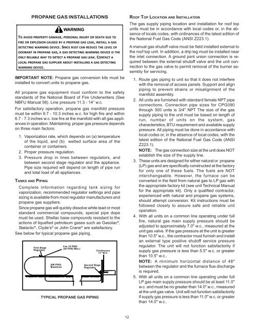
See below for typical propane gas piping.<br />
First Stage<br />
Regulator<br />
200 PSIG<br />
Maximum<br />
5 to 15 PSIG<br />
(20 PSIG Max.)<br />
Second Stage<br />
Regulator<br />
TYPICAL PROPANE <strong>GAS</strong> PIPING<br />
Continuous<br />
11" W.C.<br />
ROOF TOP LOCATION AND INSTALLATION<br />
The gas supply piping location and installation for roof top<br />
units must be in accordance with local codes or, in the absence<br />
of locals codes, with ordinances of the latest edition of<br />
the National Fuel Gas Code (ANSI Z223.1).<br />
A manual gas shutoff valve must be field installed external to<br />
the roof top unit. In addition, a drip leg must be installed near<br />
the inlet connection. A ground joint union connection is required<br />
between the external shutoff valve and the unit connection<br />
to the gas valve to permit removal of the burner assembly<br />
for servicing.<br />
1. Route gas piping to unit so that it does not interfere<br />
with the removal of access panels. Support and align<br />
piping to prevent strains or misalignment of the<br />
manifold assembly.<br />
2. All units are furnished with standard female NPT pipe<br />
connections. Connection pipe sizes for <strong>CPG</strong>090<br />
through 300 units is 3/4" NPT The size of the gas<br />
supply piping to the unit must be based on length of<br />
run, number of units on the system, gas<br />
characteristics, BTU requirement and available supply<br />
pressure. All piping must be done in accordance with<br />
local codes or, in the absence of local codes, with the<br />
latest edition of the National Fuel Gas Code (ANSI<br />
Z223.1).<br />
NOTE: The gas connection size at the unit does NOT<br />
establish the size of the supply line.<br />
3. These units are designed for either natural or propane<br />
(LP) gas and are specifically constructed at the factory<br />
for only one of these fuels. The fuels are NOT<br />
interchangeable. However, the furnace can be<br />
converted in the field from natural gas to LP gas with<br />
the appropriate factory kit (see unit Technical Manual<br />
for the appropriate kit). Only a qualified contractor,<br />
experienced with natural and propane gas systems,<br />
should attempt conversion. Kit instructions must be<br />
followed closely to assure safe and reliable unit<br />
operation.<br />
4. With all units on a common line operating under full<br />
fire, natural gas main supply pressure should be<br />
adjusted to approximately 7.0" w.c., measured at the<br />
unit gas valve. If the gas pressure at the unit is greater<br />
than 10.5" w.c., the contractor must furnish and install<br />
an external type positive shutoff service pressure<br />
regulator. The unit will not function satisfactorily if<br />
supply gas pressure is less than 5.5" w.c. or greater<br />
than 10.5" w.c..<br />
NOTE: A minimum horizontal distance of 48"<br />
between the regulator and the furnace flue discharge<br />
is required.<br />
5. With all units on a common line operating under full<br />
LP gas main supply pressure should be at least 11.0"<br />
w.c. and must be no greater than 14.0" w.c., measured<br />
at the unit gas valve. Unit will not function satisfactorily<br />
if supply gas pressure is less than 11.0" w.c. or greater<br />
than 14.0" w.c..<br />
12