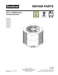
7.5 TON - 12.5 TON PACKAGE GAS SERIES CPG SERIES - Goodman
7.5 TON - 12.5 TON PACKAGE GAS SERIES CPG SERIES - Goodman
7.5 TON - 12.5 TON PACKAGE GAS SERIES CPG SERIES - Goodman

You also want an ePaper? Increase the reach of your titles
YUMPU automatically turns print PDFs into web optimized ePapers that Google loves.
CAUTION<br />
CONDUIT AND FITTINGS MUST BE WEATHER‐TIGHT TO PREVENT WATER<br />
ENTRY INTO THE BUILDING.<br />
For unit protection, use a fuse or HACR circuit breaker that is<br />
in excess of the circuit ampacity, but less than or equal to the<br />
maximum overcurrent protection device. DO NOT EXCEED<br />
THE MAXIMUM OVERCURRENT DEVICE SIZE SHOWN<br />
ON UNIT DATA PLATE.<br />
(ANSI-NFPA 70). A ground lug is provided for this<br />
purpose. Size grounding conductor in accordance<br />
with Table 250-95 of the National Electrical Code. Do<br />
not use the ground lug for connecting a neutral<br />
conductor.<br />
• Connect power wiring to the middle contactor within<br />
the main control box.<br />
FAN C<br />
RCCF<br />
FAN C<br />
RCCF<br />
All line voltage connections must be made through weatherproof<br />
fittings. All exterior power supply and ground wiring<br />
must be in approved weatherproof conduit.<br />
6<br />
3<br />
2<br />
4<br />
1<br />
The main power supply wiring to the unit and low voltage<br />
wiring to accessory controls must be done in accordance with<br />
these instructions, the latest edition of the National Electrical<br />
Code (ANSI/NFPA 70), and all local codes and ordinances.<br />
All field wiring shall conform with the temperature limitations<br />
for Type T wire (63°F/35°C rise).<br />
POWER<br />
WIRING<br />
The main power supply shall be three-phase, three wire. The<br />
unit is factory wired for the voltage shown on the unit’s data<br />
plate.<br />
NOTE: If supply voltage is 208V, all leads on primary of transformer<br />
TRANS1 must be moved from the 230V to the 208V<br />
tap.<br />
Main power wiring should be sized for the minimum wire<br />
ampacity shown on the unit’s database. Size wires in accordance<br />
with the ampacity tables in Article 310 of the National<br />
Electrical Code. If long wires are required, it may be necessary<br />
to increase the wire size to prevent excessive voltage<br />
drop. Wires should be sized for a maximum of 3% voltage<br />
drop.<br />
CAUTION<br />
TO AVOID PROPERTY DAMAGE OR PERSONAL INJURY DUE TO FIRE, USE<br />
ONLY COPPER CONDUCTORS.<br />
CAUTION<br />
TO PREVENT IMPROPER AND DANGEROUS OPERATION DUE TO WIRING<br />
ERRORS, LABEL ALL WIRES PRIOR TO DISCONNECTION WHEN SERVICING<br />
CONTROLS. VERIFY PROPER OPERATION AFTER SERVICING.<br />
NOTE: A weather-tight disconnect switch, properly sized for<br />
the unit total load, must be field installed. An external field<br />
supplied disconnect may be mounted on the exterior panel.<br />
Ensure the data plate is not covered by the field-supplied<br />
disconnect switch.<br />
• Some disconnect switches are not fused. Protect the<br />
power leads at the point of distribution in accordance<br />
with the unit data plate.<br />
• The unit must be electrically grounded in accordance<br />
with local codes or, in the absence of local codes,<br />
with the latest edition of the National Electrical Code<br />
POWER AND LOW VOLTAGE BLOCK LOCATIONS<br />
WARNING<br />
THERMOSTAT<br />
WIRING<br />
FAILURE OF UNIT DUE TO OPERATION ON IMPROPER LINE VOLTAGE OR<br />
WITH EXCESSIVE PHASE UNBALANCE CONSTITUTES PRODUCT ABUSE AND<br />
WILL VOID YOUR WARRANTY AND MAY CAUSE SEVERE DAMAGE TO THE<br />
UNIT ELECTRICAL COMPONENTS.<br />
AREAS WITHOUT CONVENIENCE OUTLET<br />
It is recommended that an independent 115V power source<br />
be brought to the vicinity of the roof top unit for portable lights<br />
and tools used by the service mechanic.<br />
UNITS INSTALLED ON ROOF TOPS<br />
Main power and low voltage wiring may enter the unit through<br />
the side or through the roof curb. Install conduit connectors<br />
at the desired entrance locations. External connectors must<br />
be weatherproof. All holes in the unit base must be sealed<br />
(including those around conduit nuts) to prevent water leakage<br />
into building. All required conduit and fittings are to be<br />
field supplied.<br />
Supply voltage to roof top unit must not vary by more than<br />
10% of the value indicated on the unit data plate. Phase<br />
voltage unbalance must not exceed 2%. Contact your local<br />
power company for correction of improper voltage or phase<br />
unbalance.<br />
9