7.5 TON - 12.5 TON PACKAGE GAS SERIES CPG SERIES - Goodman
7.5 TON - 12.5 TON PACKAGE GAS SERIES CPG SERIES - Goodman
7.5 TON - 12.5 TON PACKAGE GAS SERIES CPG SERIES - Goodman

You also want an ePaper? Increase the reach of your titles
YUMPU automatically turns print PDFs into web optimized ePapers that Google loves.
The rating plate is stamped with the model number, type of<br />
gas and gas input rating. Make sure the unit is equipped to<br />
operate on the type of gas available. The gas line installation<br />
must comply with local codes, or in the absence of local codes,<br />
with the latest edition of the National Fuel Gas Code NFPA<br />
54/ANSI Z223.1.<br />
Natural Gas Connection<br />
Natural Gas Capacity of Pipe<br />
in Cubic Feet of Gas Per Hour (CFH)<br />
Length of<br />
Nominal Black Pipe Size (inches)<br />
Pipe in Feet 1/2 3/4 1 1 1/4 1 1/2<br />
10 132 278 520 1050 1600<br />
20 92 190 350 730 1100<br />
30 73 152 285 590 980<br />
40 63 130 245 500 760<br />
50 56 115 215 440 670<br />
60 50 105 195 400 610<br />
70 46 96 180 370 560<br />
80 43 90 170 350 530<br />
90 40 84 160 320 490<br />
100 38 79 150 305 460<br />
Pressure = .50 PSIG or less and Pressure Drop of 0.3" W.C. (Based<br />
on 0.60 Specific Gravity Gas)<br />
BTUH Furnace Input<br />
CFH =<br />
Heating Value of Gas (BTU/Cubic Foot)<br />
Refer to the Proper Piping Practice drawing for the general<br />
layout at the unit. The following rules apply:<br />
1. Use black iron pipe and fittings for the supply piping.<br />
The use of a flex connector and/or copper piping is<br />
permitted as long as it is in agreement with local<br />
codes.<br />
2. Use pipe joint compound on male threads only. Pipe<br />
joint compound must be resistant to the action of the<br />
fuel used.<br />
3. Use ground joint unions.<br />
4. Install a drip leg to trap dirt and moisture before it can<br />
enter the gas valve. The drip leg must be a minimum<br />
of three inches long.<br />
5. Use two pipe wrenches when making connection to<br />
the gas valve to keep it from turning.<br />
6. Install a manual shut-off valve in a convenient location<br />
(within six feet of unit) between the meter and the<br />
unit.<br />
7. Tighten all joints securely.<br />
8. The unit must be connected to the building piping by<br />
one of the following methods:<br />
• Rigid metallic pipe and fittings<br />
• Semirigid metallic tubing and metallic fittings<br />
(Aluminum alloy tubing must not be used in exterior<br />
locations)<br />
• Listed gas appliance connectors used in accordance<br />
with the terms of their listing that are completely in<br />
the same room as the equipment<br />
• In the prior two methods above the connector or<br />
tubing must be protected from physical and thermal<br />
damage. Aluminum alloy tubing and connectors must<br />
be coated to protect against external corrosion when<br />
in contact with masonry, plaster or insulation or are<br />
subject to repeated wettings by liquids (water - not<br />
rain water, detergents or sewage).<br />
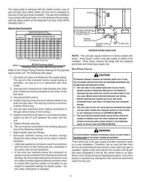
DOOR<br />
PROVIDE CLEARANCE<br />
FOR REMOVAL OF<br />
ACCESS PANELS<br />
MANUAL<br />
SHUTOFF VALVE<br />
GROUND JOINT<br />
UNION<br />
PROPER PIPING PRACTICE<br />
DRIP LEG<br />
NOTE: The unit gas supply entrance is factory sealed with<br />
plugs. Keep plugs in place until gas supply is ready to be<br />
installed. Once ready, replace the plugs with the supplied<br />
grommets and install gas supply line.<br />
<strong>GAS</strong> PIPING CHECKS<br />
CAUTION<br />
TO PREVENT PROPERTY DAMAGE OR PERSONAL INJURY DUE TO FIRE,<br />
THE FOLLOWING INSTRUCTIONS MUST BE PERFORMED REGARDING <strong>GAS</strong><br />
CONNECTIONS AND PRESSURE TESTING:<br />
• THE UNIT AND ITS <strong>GAS</strong> CONNECTIONS MUST BE LEAK TESTED<br />
BEFORE PLACING IN OPERATION. BECAUSE OF THE DANGER OF<br />
EXPLOSION OR FIRE, NEVER USE A MATCH OR OPEN FLAME TO TEST<br />
FOR LEAKS. NEVER EXCEED SPECIFIED PRESSURES FOR TESTING.<br />
HIGHER PRESSURE MAY DAMAGE <strong>GAS</strong> VALVE AND CAUSE<br />
OVERFIRING WHICH MAY RESULT IN PREMATURE HEAT EXCHANGE<br />
FAILURE.<br />
• THIS UNIT AND ITS SHUT‐OFF VALVE MUST BE DISCONNECTED FROM<br />
THE <strong>GAS</strong> SUPPLY DURING ANY PRESSURE TESTING OF THAT SYSTEM<br />
AT TEST PRESSURES IN EXCESS OF 1/2 PSIG (3.48 KPA).<br />
• THIS UNIT MUST BE ISOLATED FROM THE <strong>GAS</strong> SUPPLY SYSTEM BY<br />
CLOSING ITS MANUAL SHUT‐OFF VALVE DURING ANY PRESSURE<br />
TESTING OF THE <strong>GAS</strong> SUPPLY PIPING SYSTEM AT TEST PRESSURES<br />
EQUAL TO OR LESS THAN 1/2 PSIG (3.48 KPA).<br />
WARNING<br />
TO AVOID PROPERTY DAMAGE OR PERSONAL INJURY, BE SURE THERE IS<br />
NO OPEN FLAME IN THE VICINITY DURING AIR BLEEDING.<br />
There will be air in the gas supply line after testing for leaks<br />
on a new installation. Therefore, the air must be bled from<br />
the line by loosening the ground joint union until pure gas is<br />
expelled. Tighten union and wait for five minutes until all gas<br />
has been dissipated in the air. Be certain there is no open<br />
flame in the vicinity during air bleeding procedure. The unit is<br />
placed in operation by closing the main electrical disconnect<br />
switch for the unit.<br />
11