Comfort Alert Users Manual Copeland - Desco Energy
Comfort Alert Users Manual Copeland - Desco Energy
Comfort Alert Users Manual Copeland - Desco Energy

You also want an ePaper? Increase the reach of your titles
YUMPU automatically turns print PDFs into web optimized ePapers that Google loves.
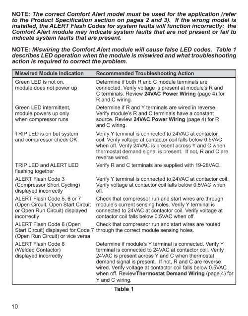
NOTE: The correct <strong>Comfort</strong> <strong>Alert</strong> model must be used for the application (refer<br />
to the Product Specification section on pages 2 and 3). If the wrong model is<br />
installed, the ALERT Flash Codes for system faults will function incorrectly: the<br />
<strong>Comfort</strong> <strong>Alert</strong> module may indicate system faults that are not present or fail to<br />
indicate system faults that are present.<br />
NOTE: Miswiring the <strong>Comfort</strong> <strong>Alert</strong> module will cause false LED codes. Table 1<br />
describes LED operation when the module is miswired and what troubleshooting<br />
action is required to correct the problem.<br />
Miswired Module Indication<br />
Green LED is not on,<br />
module does not power up<br />
Green LED intermittent,<br />
module powers up only<br />
when compressor runs<br />
TRIP LED is on but system<br />
and compressor check OK<br />
TRIP LED and ALERT LED<br />
fl ashing together<br />
ALERT Flash Code 3<br />
(Compressor Short Cycling)<br />
displayed incorrectly<br />
Recommended Troubleshooting Action<br />
Determine if both R and C module terminals are<br />
connected. Verify voltage is present at module’s R and<br />
C terminals. Review 24VAC Power Wiring (page 4) for<br />
R and C wiring.<br />
Determine if R and Y terminals are wired in reverse.<br />
Verify module’s R and C terminals have a constant<br />
source. Review 24VAC Power Wiring (page 4) for R<br />
and C wiring.<br />
Verify Y terminal is connected to 24VAC at contactor<br />
coil. Verify voltage at contactor coil falls below 0.5VAC<br />
when off. Verify 24VAC is present across Y and C when<br />
thermostat demand signal is present. If not, R and C are<br />
reverse wired.<br />
Verify R and C terminals are supplied with 19-28VAC.<br />
Verify Y terminal is connected to 24VAC at contactor coil.<br />
Verify voltage at contactor coil falls below 0.5VAC when<br />
off.<br />
ALERT Flash Code 5, 6 or 7 Check that compressor run and start wires are through<br />
(Open Circuit, Open Start Circuit module’s current sensing holes. Verify Y terminal is<br />
or Open Run Circuit) displayed connected to 24VAC at contactor coil. Verify voltage at<br />
incorrectly<br />
contactor coil falls below 0.5VAC when off.<br />
ALERT Flash Code 6 (Open Check that compressor run and start wires are routed<br />
Start Circuit) displayed for Code 7 through the correct module sensing holes.<br />
(Open Run Circuit) or vice versa<br />
ALERT Flash Code 8<br />
(Welded Contactor)<br />
displayed incorrectly<br />
Determine if module’s Y terminal is connected. Verify Y<br />
terminal is connected to 24VAC at contactor coil. Verify<br />
24VAC is present across Y and C when thermostat<br />
demand signal is present. If not, R and C are reverse<br />
wired. Verify voltage at contactor coil falls below 0.5VAC<br />
when off. ReviewThermostat Demand Wiring (page 4) for<br />
Y and C wiring.<br />
Table 1<br />
10