Comfort Alert Users Manual Copeland - Desco Energy
Comfort Alert Users Manual Copeland - Desco Energy
Comfort Alert Users Manual Copeland - Desco Energy

Create successful ePaper yourself
Turn your PDF publications into a flip-book with our unique Google optimized e-Paper software.
Interpreting The Diagnostic LEDs<br />
When an abnormal system condition occurs, the <strong>Comfort</strong> <strong>Alert</strong> module displays the<br />
appropriate ALERT and/or TRIP LED. The yellow ALERT LED will fl ash a number of<br />
times consecutively, pause and then repeat the process. To identify a Flash Code<br />
number, count the number of consecutive fl ashes. Every time the module powers<br />
up, the last ALERT Flash Code that occurred prior to shut down is displayed for one<br />
minute.<br />
Installation Verification<br />
To verify the installation of <strong>Comfort</strong> <strong>Alert</strong> is correct, two functional tests can be performed.<br />
Disconnect power from the compressor and force a thermostat call for cooling. The red<br />
Trip LED should turn on indicating a compressor trip as long as 24VAC is measured at<br />
the Y terminal. If the red LED does not function as described, refer to Table 1 to verify<br />
the wiring.<br />
Disconnect power from the compressor and 24VAC from <strong>Comfort</strong> <strong>Alert</strong>. Remove the<br />
wire from the Y terminal of <strong>Comfort</strong> <strong>Alert</strong>, reapply 24VAC power to <strong>Comfort</strong> <strong>Alert</strong> and<br />
reconnect power to the compressor. Force a thermostat call for cooling and when the<br />
Compressor starts to run, the yellow <strong>Alert</strong> LED will begin fl ashing a Code 8 indicating<br />
a Welded Contactor. Disconnect power from the compressor and 24VAC from <strong>Comfort</strong><br />
<strong>Alert</strong>. While <strong>Comfort</strong> <strong>Alert</strong> is off, reattach the wire to the Y terminal. Reapply power to<br />
compressor and 24VAC to <strong>Comfort</strong> <strong>Alert</strong>, the yellow <strong>Alert</strong> LED will fl ash the previous<br />
code 8 for 1 minute and then turn off. If the yellow LED does not function as described,<br />
refer to Table 1 to verify the wiring.<br />
Troubleshooting The Installation<br />
Depending on the system confi guration, some ALERT Flash codes may not be active.<br />
The presence of safety switches affects how the system alerts are displayed by this<br />
module. Refer to Figures 4 & 5 for safety switch wiring.<br />
Resetting <strong>Alert</strong> Codes<br />
<strong>Alert</strong> codes can be reset manually and automatically. The manual method to reset an <strong>Alert</strong><br />
code is to cycle the power to <strong>Comfort</strong> <strong>Alert</strong> off and on. For automatic reset, <strong>Comfort</strong> <strong>Alert</strong><br />
continues to monitor the compressor and system after an <strong>Alert</strong> is detected. If conditions<br />
return to normal, the <strong>Alert</strong> code is turned off automatically.<br />
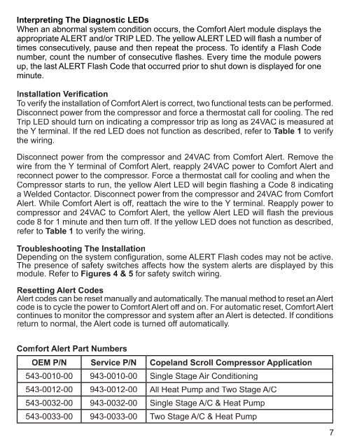
<strong>Comfort</strong> <strong>Alert</strong> Part Numbers<br />
OEM P/N Service P/N <strong>Copeland</strong> Scroll Compressor Application<br />
543-0010-00 943-0010-00 Single Stage Air Conditioning<br />
543-0012-00 943-0012-00 All Heat Pump and Two Stage A/C<br />
543-0032-00 943-0032-00 Single Stage A/C & Heat Pump<br />
543-0033-00 943-0033-00 Two Stage A/C & Heat Pump<br />
7