Comfort Alert Users Manual Copeland - Desco Energy
Comfort Alert Users Manual Copeland - Desco Energy
Comfort Alert Users Manual Copeland - Desco Energy

You also want an ePaper? Increase the reach of your titles
YUMPU automatically turns print PDFs into web optimized ePapers that Google loves.
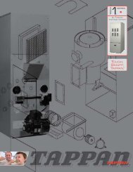
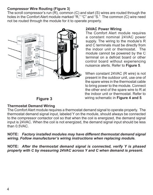
Compressor Wire Routing (Figure 3)<br />
The scroll compressor’s run (R), common (C) and start (S) wires are routed through the<br />
holes in the <strong>Comfort</strong> <strong>Alert</strong> module marked “R,” “C” and “S.” The common (C) wire need<br />
not be routed through the module for it to operate properly.<br />
Figure 3<br />
24VAC Power Wiring<br />
The <strong>Comfort</strong> <strong>Alert</strong> module requires<br />
a constant nominal 24VAC power<br />
supply. The wiring to the module’s R<br />
and C terminals must be directly from<br />
the indoor unit or thermostat. The<br />
module cannot be powered by the C<br />
terminal on a defrost board or other<br />
control board without experiencing<br />
nuisance alerts. Refer to Figure 5.<br />
When constant 24VAC (R wire) is not<br />
present in the outdoor unit, use one of<br />
the spare wires in the thermostat cable<br />
to bring power to the module. Connect<br />
the other end of the spare wire to R at<br />
the indoor unit or thermostat. Refer to<br />
wiring schematic in Figure 4 and 5.<br />
Thermostat Demand Wiring<br />
The <strong>Comfort</strong> <strong>Alert</strong> module requires a thermostat demand signal to operate properly. The<br />
thermostat demand signal input, labeled Y on the module, should always be connected<br />
to the compressor contactor coil so that when the coil is energized, the demand signal<br />
input is 24VAC. When the coil is not energized, the demand signal input should be less<br />
than 0.5VAC.<br />
NOTE: Factory installed modules may have different thermostat demand signal<br />
wiring. Follow manufacturer’s wiring instructions when replacing module.<br />
NOTE: After the thermostat demand signal is connected, verify Y is phased<br />
properly with C by measuring 24VAC across Y and C when demand is present.<br />
4