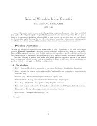
CS-184: Computer Graphics Today - Inst.eecs.berkeley.edu ...
CS-184: Computer Graphics Today - Inst.eecs.berkeley.edu ...
CS-184: Computer Graphics Today - Inst.eecs.berkeley.edu ...

You also want an ePaper? Increase the reach of your titles
YUMPU automatically turns print PDFs into web optimized ePapers that Google loves.
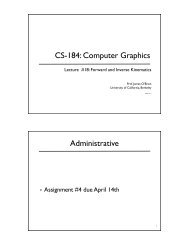
<strong>CS</strong>-<strong>184</strong>: <strong>Computer</strong> <strong>Graphics</strong><br />
Lecture #9: Texture and Other Maps<br />
Lecture by Adam Bargeil<br />
Prof. James O’Brien<br />
University of California, Berkeley<br />
V2005-09-1.1<br />
1<br />
<strong>Today</strong><br />
Maps<br />
Texture Mapping<br />
Bump Mapping<br />
Displacement Mapping<br />
Shadow Maps<br />
Environment Maps<br />
Compositing<br />
2<br />
2
Surface Detail<br />
The real world is<br />
complicated<br />
We can’t explicitly<br />
model all the rich<br />
detail<br />
So, we come up<br />
with some<br />
“hacks”...<br />
3<br />
3<br />
Texture Mapping<br />
The idea is to wrap a “texture” onto a<br />
surface<br />
To do this we need<br />
A texture, usually just an image<br />
A parameterization of the surface<br />
A mapping from the surface parameterization to the<br />
texture coordinates<br />
4<br />
4
Barycentric Coordinates<br />
X<br />
can be expressed as<br />
!P 1 + "P 2 + #P 3<br />
where<br />
! + " + # = 1<br />
or, alternatively as<br />
X<br />
P 1<br />
P 2<br />
P 3<br />
(1 − ! − ")P 1 + !P 2 + "P 3<br />
5<br />
5<br />
Barycentric Coordinates<br />
We can use barycentric<br />
coordinates to interpolate<br />
any quantity (color,<br />
texture coordinates, etc)<br />
stored at vertices, not just<br />
positions.<br />
X<br />
P 1<br />
P 2<br />
P 3<br />
6<br />
6
Bad Idea<br />
Simplest (and fastest)<br />
approach is to<br />
compute texture<br />
coordinates for<br />
polygon vertices and<br />
interpolate in screen<br />
space.<br />
This gives the image on<br />
the right.<br />
7<br />
7<br />
Undoing Homogenization<br />
Let P i = (x i ,y i ,z i ,h i ) be the i th point of some<br />
polygon, after projection, but before<br />
homogenization<br />
The homogenized point S i = P i /h is the<br />
location of on the screen.<br />
P i<br />
Let X be a point we wish to shade, we have<br />
its barycentric coordinates in screen space:<br />
X = ! b i S i<br />
i<br />
8<br />
8
Undoing Homogenization<br />
We know<br />
We also know that there exist weights ,<br />
such that<br />
X = (! a i P i )/(! a j h j )<br />
i<br />
j<br />
Combining the above we have<br />
a j h j )<br />
!<br />
i<br />
!<br />
i<br />
S i = P i /h<br />
b i S i = X = (!<br />
i<br />
b i (P i /h i ) = (!<br />
i<br />
a i P i )/(!<br />
j<br />
a i P i )/(!<br />
j<br />
a j h j )<br />
a i<br />
9<br />
9<br />
Undoing Homogenization<br />
b i /h i = a i /(! a j h j )<br />
j<br />
a j h j )/h i = a i<br />
b i (!<br />
j<br />
b i (! a j h j )/h i − a i = 0<br />
j<br />
∀i<br />
∀i<br />
This is a linear system in<br />
∀i<br />
Unfortunately is is non-invertible, so...<br />
a i<br />
10<br />
10
Undoing Homogenization<br />
we add<br />
! a i = 1 ! b i = 1<br />
i<br />
i<br />
now its solvable and the solution is:<br />
h 2 h 3 b 1<br />
a 1 =<br />
h 2 h 3 b 1 + h 1 h 3 b 2 + h 1 h 2 b 3<br />
similar formulas exist for<br />
and<br />
a 2 a 3<br />
11<br />
11<br />
Bump/Displacement Mapping<br />
Texture mapping<br />
changes a surface’s<br />
reflectance, but<br />
that can’t give us a<br />
realistic orange<br />
For this we can<br />
use bump or<br />
displacement<br />
mapping<br />
12<br />
12
Bump Mapping<br />
The idea is to perturb the surface normals<br />
If the bump map is an array of vectors, just<br />
add the bump vectors to the surface<br />
normals<br />
If the bump map is an array of scalars<br />
(desired displacements along the normal<br />
direction), then the new normal is<br />
n ′ = n + b u (n × P v ) − b v (n × P u )<br />
13<br />
13<br />
Displacement Mapping<br />
Actually perturb the location of the surface,<br />
usually along the normal direction, by scalar<br />
values given in the displacement map<br />
This is usually done by moving the vertices<br />
of a polygonal mesh<br />
14<br />
14
Bumps vs. Displacements<br />
Bumps do not cast shadows or<br />
change the silhouette, they do<br />
produce specular effects<br />
Displacements actually change<br />
the geometry<br />
Displacement maps only look<br />
good on high resolution models<br />
Bottom line: bumps are cheaper,<br />
displacements look better<br />
15<br />
15<br />
Shadow Maps<br />
Key insight: If we render the scene from the<br />
point of view of the light source, the lit<br />
surfaces will be visible and the unlit surfaces<br />
will by hidden<br />
We render the scene from the point of view<br />
of the light source<br />
Store the z values in a “depth shadow map”<br />
16<br />
16
Shadow Maps<br />
For each polygon<br />
Render the polygon from the camera<br />
Render the polygon from the light<br />
Compare the z value from the light with the one in<br />
the depth shadow map<br />
If they match, the polygon is lit<br />
Otherwise it is in shadow<br />
17<br />
17<br />
Environment Maps<br />
Fake reflections<br />
Assumes the environment is very far away<br />
Depends on the location of the camera<br />
Usually stored in a spherical table or a cube<br />
map<br />
18<br />
18
Environment Maps<br />
Remove the reflective object<br />
from the scene<br />
Render the scene six times<br />
with the eye at the center of<br />
the removed object<br />
Render the scene, using<br />
reflection vectors to index<br />
the cube map<br />
19<br />
19<br />
Compositing<br />
Sometimes scenes are too complex to<br />
render all at once<br />
Different parts of a scene often do not<br />
interact<br />
Need a way to render pieces separately and<br />
put them back together later<br />
20<br />
20
Alpha Channels<br />
Alpha channel<br />
stores opacity<br />
Primary operation<br />
is “over”<br />
Pre-multiplied alpha<br />
allows the use of<br />
the same rules for<br />
all 4 channels<br />
Normal Alpha Channel<br />
c = !c f + (1 − !)c b<br />
Pre-multiplied Alpha Channel<br />
c = c f + (1 − !)c b<br />
background RGB foreground RGB ! channel<br />
21<br />
21<br />
Alpha Channel<br />
Other Operations<br />
c = Fc f + Gc g<br />
22<br />
Operation<br />
Over<br />
Inside<br />
Outside<br />
Atop<br />
Xor<br />
Clear<br />
Set<br />
F<br />
1<br />
g<br />
G<br />
1"! f<br />
! 0<br />
1"! g<br />
0<br />
1"! f<br />
! g<br />
1"! g<br />
1"!<br />
f<br />
0 0<br />
1 0<br />
22
Suggested Reading<br />
Fundamentals of <strong>Computer</strong> <strong>Graphics</strong> by<br />
Pete Shirley<br />
Chapters 10, 3.4<br />
23<br />
23