Manual - Cool Italia GmbH
Manual - Cool Italia GmbH
Manual - Cool Italia GmbH

Create successful ePaper yourself
Turn your PDF publications into a flip-book with our unique Google optimized e-Paper software.
,QVWDOOLQJ DQG 2SHUDWLQJ ,QVWUXFWLRQV UHO FRG <br />
:,1*<br />
)&<br />
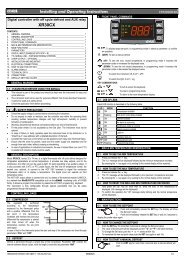
1. GENERAL WARNING<br />
;:/ ² ;:9<br />
To display and modify target set point; in programming mode it selects a parameter or confirm an<br />
operation.<br />
By holding it pressed for 3s when max or min temperature is displayed it will be erased.<br />
1.1 PLEASE READ BEFORE USING THIS MANUAL<br />
• This manual is part of the product and should be kept near the instrument for easy and quick reference.<br />
• The instrument shall not be used for purposes different from those described hereunder. It cannot be used<br />
as a safety device.<br />
• Check the application limits before proceeding.<br />
To see the max. stored temperature; in programming mode it browses the parameter codes or<br />
increases the displayed value. By holding it pressed for 3s the fast freezing cycle is started.<br />
To see the min stored temperature; in programming mode it browses the parameter codes or<br />
decreases the displayed value.<br />
By holding it pressed for 3s the defrost is started.<br />
1.2 SAFETY PRECAUTIONS<br />
• Check the supply voltage is correct before connecting the instrument.<br />
• Do not expose to water or moisture: use the controller only within the operating limits avoiding sudden<br />
temperature changes with high atmospheric humidity to prevent formation of condensation<br />
• Warning: disconnect all electrical connections before any kind of maintenance.<br />
• Fit the probe where it is not accessible by the End User. The instrument must not be opened.<br />
• In case of failure or faulty operation send the instrument back to the distributor or to “Dixell S.p.A” (see<br />
address) with a detailed description of the fault.<br />
• Consider the maximum current which can be applied to each relay (see Technical Data).<br />
• Ensure that the wires for probes, loads and the power supply are separated and far enough from each other,<br />
without crossing or intertwining.<br />
• In case of applications in industrial environments, the use of mains filters (our mod. FT1) in parallel with<br />
inductive loads could be useful.<br />
2. GENERAL DESCRIPTION<br />
Model XW60L, 38x185 mm format, and model XW60V, 100x64 format, are microprocessor based controllers<br />
suitable for applications on medium or low temperature refrigerating units. They are provided with four relay<br />
outputs to control compressor, defrost - which can be either electrical or hot gas - the evaporator fans and the<br />
lights. They are also provided with 2 NTC or PTC probe inputs, one for temperature control, one to control the<br />
defrost end temperature of the evaporator. There are 1 digital inputs (free contact) configurable by parameter. An<br />
output allows the user to programme the parameter list with the “Hot Key”.<br />
3. CONTROLLING LOADS<br />
3.1 THE COMPRESSOR<br />
The regulation is performed according to the temperature measured by the thermostat probe with a positive<br />
differential from the set point: if the temperature increases and reaches set point plus differential the compressor is<br />
started and then turned off when the temperature reaches the set point value again.<br />
In case of fault in the thermostat probe the start and stop of the compressor are timed through parameters “COn”<br />
and “COF”.<br />
3.2 FAST FREEZING<br />
When defrost is not in progress, it can be activated the keypad by holding the 9 key pressed for about 3<br />
seconds. The compressor operates in continuous mode for the time set through the “CCt” parameter. The cycle<br />
can be terminated before the end of the set time using the same activation key, 9 for about 3 seconds.<br />
3.3 DEFROST<br />
Two defrost modes are available through the “tdF” parameter: defrost with electrical heater or hot gas. The defrost<br />
interval is control by means of parameter “EdF”: (EdF=in) the defrost is made every “IdF” time, (EdF=Sd) the<br />
interval “IdF” is calculate through Smart Defrost algorithm (only when the compressor is ON).<br />
3.4 CONTROL OF EVAPORATOR FANS<br />
The fan control mode is selected by means of the “FnC” parameter:<br />
FnC=C-n fans will switch ON and OFF with the compressor and not run during defrost:;<br />
FnC= O-n fans will run continuously, but not during defrost<br />
After defrost, there is a timed fan delay allowing for drip time, set by means of the “Fnd” parameter.<br />
FnC=C-y fans will switch ON and OFF with the compressor and run during defrost;<br />
FnC=O-y fans will run continuously also during defrost<br />
An additional parameter “FSt” provides the setting of temperature, detected by the evaporator probe, above which<br />
the fans are always OFF. This can be used to make sure circulation of air only if his temperature is lower than set<br />
in “FSt”.<br />
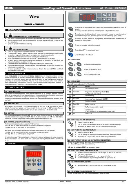
4. KEYBOARD<br />
KEY COMBINATIONS<br />
Switch ON and OFF the light of the cold-room<br />
Switch ON and OFF the instrument.<br />
+<br />
To lock and unlock the keyboard.<br />
+<br />
To enter the programming mode.<br />
+<br />
To exit the programming mode.<br />
4.1 USE OF LEDS<br />
Each LED function is described in the following table.<br />
LED MODE Function<br />
ON<br />
The compressor is running<br />
FLASHING - Programming Phase (flashing with LED )<br />
- Anti-short cycle delay enabled<br />
ON<br />
The fan is running<br />
FLASHING<br />
Programming Phase (flashing with LED )<br />
ON<br />
FLASHING<br />
ON<br />
ON<br />
ON<br />
The defrost is enabled<br />
Drip time in progress<br />
The Fast Freezing cycle is enabled<br />
- ALARM signal<br />
- In “Pr2” indicates that the parameter is also present in “Pr1”<br />
The light is on<br />
4.2 HOW TO SEE THE MIN TEMPERATURE<br />
1. Press and release the 8 key.<br />
2. The “Lo” message will be displayed followed by the minimum temperature recorded.<br />
3. By pressing the 8 key or waiting for 5s the normal display will be restored.<br />
4.3 HOW TO SEE THE MAX TEMPERATURE<br />
1. Press and release the 9 key.<br />
2. The “Hi” message will be displayed followed by the maximum temperature recorded.<br />
3. By pressing the 9 key or waiting for 5s the normal display will be restored.<br />
4.4 HOW TO RESET THE MAX AND MIN TEMPERATURE RECORDED<br />
To reset the stored temperature, when max or min temperature is displayed :<br />
1. Press SET key until “rST” label starts blinking.<br />
N.B. After the installation RESET the temperature stored .<br />
4.5 HOW TO SEE AND MODIFY THE SET POINT<br />
1. Push and immediately release the SET key: the display will show the Set point value;<br />
2. The SET LED start blinking;<br />
3. To change the Set value push the 9 or 8 arrows within 10s.<br />
4. To memorise the new set point value push the SET key again or wait 10s.<br />
4.6 TO START A MANUAL DEFROST<br />
1. Push the DEF key for more than 2 seconds and a manual defrost will start.<br />
4.7 TO ENTER IN PARAMETERS LIST “PR1”<br />
To enter the parameter list “Pr1” (user accessible parameters) operate as follows:<br />
1592009267 XW60L-V GB r1.0 15.12.2004.doc ;:/ ² ;:9 1/4
,QVWDOOLQJ DQG 2SHUDWLQJ ,QVWUXFWLRQV UHO FRG <br />
1. Enter the Programming mode by pressing the Set and DOWN key for few seconds<br />
( and start blinking).<br />
2. The instrument will show the first parameter present in “Pr1”<br />
4.8 TO ENTER IN PARAMETERS LIST “PR2”<br />
To access parameters in “Pr2”:<br />
1. Enter the “Pr1” level.<br />
2. Select “Pr2” parameter and press the “SET” key.<br />
3. The “PAS” flashing message is displayed, shortly followed by “0 - -” with a flashing zero.<br />
4. Use 9 or 8 to input the security code in the flashing digit; confirm the figure by pressing “SET”. The<br />
security code is “321“.<br />
5. If the security code is correct the access to “Pr2” is enabled by pressing “SET” on the last digit.<br />
Another possibility is the following: after switching ON the instrument the user can push Set and DOWN keys<br />
within 30 seconds.<br />
NOTE: each parameter in “Pr2” can be removed or put into “Pr1” (user level) by pressing “SET” + 8. When a<br />
parameter is present in “Pr1” LED is on.<br />
4.9 HOW TO CHANGE THE PARAMETER VALUE<br />
1. Enter the Programming mode.<br />
2. Select the required parameter with 9 or 8.<br />
3. Press the “SET” key to display its value ( and LED starts blinking).<br />
4. Use 9 or 8 to change its value.<br />
5. Press “SET” to store the new value and move to the following parameter.<br />
To exit: Press SET + UP or wait 15s without pressing a key.<br />
NOTE: the new programming is stored even when the procedure is exited by waiting the time-out.<br />
4.10 HOW TO LOCK THE KEYBOARD<br />
1. Keep the 9 and 8 keys pressed together for more than 3 s the 9 and 8 keys.<br />
2. The “POF” message will be displayed and the keyboard is locked. At this point it is only<br />
possible the viewing of the set point or the MAX o Min temperature stored and to switch ON<br />
and OFF the light, the auxiliary output and the instrument.<br />
TO UNLOCK THE KEYBOARD<br />
Keep the 9 and 8 keys pressed together for more than 3s.<br />
4.11 ON/OFF FUNCTION<br />
By pushing the ON/OFF key, the instrument shows “OFF” for 5 sec. and the ON/OFF LED is<br />
switched ON.<br />
During the OFF status, all the relays are switched OFF and the regulations are stopped;<br />
N.B. During the OFF status the Light button is active.<br />
4.12 TO SEE THE PROBE VALUES<br />
1. Enter in “Pr2” level.<br />
2. Select “Prd” parameter with 9 or 8.<br />
3. Press the “SET” key to display “Pb1” label alternate with Pb1 value.<br />
4. Use 9 and 8 keys to display the other probe values.<br />
5. Press “SET” to move to the following parameter.<br />
5. PARAMETER LIST<br />
REGULATION<br />
Hy Differential: (0,1÷25,5°C; 1÷45°F): Intervention differential for set point, always positive. Compressor Cut<br />
IN is Set Point Plus Differential (Hy). Compressor Cut OUT is when the temperature reaches the set point.<br />
LS Minimum set point limit: (-50,0°C÷SET; -58°F÷SET) Sets the minimum acceptable value for the set<br />
point.<br />
US Maximum set point limit: (SET÷110°C; SET÷230°F) Set the maximum acceptable value for set point.<br />
OdS Outputs activation delay at start up: (0÷255 min) This function is enabled at the initial start up of the<br />
instrument and inhibits any output activation for the period of time set in the parameter. (Light can work)<br />
AC Anti-short cycle delay: (0÷30 min) interval between the compressor stop and the following restart.<br />
CCt Thermostat override: (0min ÷23h 50min) allows to set the length of the continuous cycle. Can be used, for<br />
instance, when the room is filled with new products.<br />
Con Compressor ON time with faulty probe: (0÷255 min) time during which the compressor is active in case<br />
of faulty thermostat probe. With COn=0 compressor is always OFF.<br />
COF Compressor OFF time with faulty probe: (0÷255 min) time during which the compressor is off in case of<br />
faulty thermostat probe. With COF=0 compressor is always active.<br />
DISPLAY<br />
CF Temperature measurement unit: °C = Celsius; °F = Fahrenheit. When the measurement unit is changed<br />
the SET point and the values of some parameters have to be modified.<br />
rES Resolution (for °C): (in = 1°C; de = 0,1°C) allows decimal point display.<br />
dE = 0,1°C; in = 1 °C<br />
Lod Local display : select which probe is displayed by the instrument:<br />
P1 = Thermostat probe<br />
P2 = Evaporator probe<br />
1r2 = difference between P1 and P2 (P1-P2)<br />
DEFROST<br />
tdF Defrost type:<br />
rE = electrical heater (Compressor OFF)<br />
in = hot gas (Compressor and defrost relays ON)<br />
EdF Defrost mode:<br />
in = interval mode. The defrost starts when the time “Idf” is expired.<br />
Sd = Smartfrost mode. The time IdF (interval between defrosts) is increased only when the compressor is<br />
running (even non consecutively).<br />
SdF Set point for SMARTFROST: (-30÷30 °C/ -22÷86 °F) evaporator temperature which allows the IdF<br />
counting (interval between defrosts) in SMARTFROST mode.<br />
dtE Defrost termination temperature: (-50,0÷110,0°C; -58÷230°F) (Enabled only when the evaporator probe<br />
is present) sets the temperature measured by the evaporator probe which causes the end of defrost.<br />
IdF Interval between defrosts: (1÷120h) Determines the time interval between the beginning of two defrost<br />
cycles.<br />
MdF (Maximum) duration of defrost: (0÷255 min) When P2P = n, no evaporator probe, it sets the defrost<br />
duration, when P2P = y, defrost end based on temperature, it sets the maximum length for defrost.<br />
dFd Display during defrost:<br />
rt = real temperature; it = temperature reading at the defrost start;<br />
Set = set point; dEF = “dEF” label; dEG = “dEG” label;<br />
dAd Defrost display time out: (0÷255 min) Sets the maximum time between the end of defrost and the<br />
restarting of the real room temperature display.<br />
dSd Start defrost delay: ( 0÷99min) This is useful when different defrost start times are necessary to avoid<br />
overloading the plant.<br />
Fdt Drain down time: (0÷60 min.) time interval between reaching defrost termination temperature and the<br />
restoring of the control’s normal operation. This time allows the evaporator to eliminate water drops that<br />
might have formed due to defrost.<br />
dPO First defrost after start-up:<br />
y = Immediately; n = after the IdF time<br />
dAF Defrost delay after fast freezing: (0min÷23h 50min) after a Fast Freezing cycle, the first defrost will be<br />
delayed for this time.<br />
FANS<br />
FnC Fan operating mode:<br />
C-n = running with the compressor, OFF during the defrost;<br />
C-y = running with the compressor, ON during the defrost;<br />
O-n = continuous mode, OFF during the defrost;<br />
O-y = continuous mode, ON during the defrost;<br />
Fnd Fan delay after defrost: (0÷255 min) The time interval between the defrost end and evaporator fans start.<br />
FSt Fan stop temperature: (-50÷110°C; -58÷230°F) setting of temperature, detected by evaporator probe,<br />
above which the fan is always OFF.<br />
ALARMS<br />
ALC Temperature alarm configuration<br />
rE = High and Low alarms related to Set Point<br />
Ab = High and low alarms related to the absolute temperature.<br />
ALU High temperature alarm setting:<br />
ALC= rE, 0 ÷ 50°C or 90°F<br />
ALC= Ab, ALL ÷ 110°C or 230°F<br />
when this temperature is reached and after the ALd delay time the HA alarm is enabled.<br />
ALL Low temperature alarm setting:<br />
ALC = rE , 0 ÷ 50 °C or 90°F<br />
ALC = Ab , - 50°C or -58°F ÷ ALU<br />
when this temperature is reached and after the ALd delay time, the LA alarm is enabled,.<br />
AFH Temperature alarm and fan differential: (0,1÷25,5°C; 1÷45°F) Intervention differential for temperature<br />
alarm set point and fan regulation set point, always positive.<br />
ALd Temperature alarm delay: (0÷255 min) time interval between the detection of an alarm condition and the<br />
corresponding alarm signalling.<br />
dAO Delay of temperature alarm at start-up: (0min÷23h 50min) time interval between the detection of the<br />
temperature alarm condition after the instrument power on and the alarm signalling.<br />
EdA Alarm delay at the end of defrost: (0÷255 min) Time interval between the detection of the temperature<br />
alarm condition at the end of defrost and the alarm signalling.<br />
dot Delay of temperature alarm after closing the door : (0÷255 min) Time delay to signal the temperature<br />
alarm condition after closing the door.<br />
doA Open door alarm delay:(0÷255 min) delay between the detection of the open door condition and its alarm<br />
signalling: the flashing message “dA” is displayed.<br />
nPS Pressure switch number: (0 ÷15) Number of activation of the pressure switch, during the “did” interval,<br />
before signalling the alarm event (I2F= PAL).<br />
If the nPS activation in the did time is reached, switch off and on the instrument to restart normal<br />
regulation.<br />
PROBE INPUTS<br />
Ot Thermostat probe calibration: (-12.0÷12.0°C/ -21÷21°F) allows to adjust possible offset of the<br />
thermostat probe.<br />
OE Evaporator probe calibration: (-12.0÷12.0°C/ -21÷21°F) allows to adjust possible offsets of the<br />
evaporator probe.<br />
P2P Evaporator probe presence: n= not present: the defrost stops only by time; y= present: the defrost stops<br />
by temperature and time.<br />
HES Temperature increase during the Energy Saving cycle : (-30,0°C ÷ 30,0°C / -22÷86°F) sets the<br />
increasing value of the set point during the Energy Saving cycle.<br />
DIGITAL INPUTS<br />
odc Compressor and fan status when open door:<br />
no = normal; Fan = Fan OFF; CPr = Compressor OFF; F_C = Compressor and fan OFF.<br />
I2P Configurable digital input polarity:<br />
CL : the digital input is activated by closing the contact;<br />
OP : the digital input is activated by opening the contact<br />
I2F Digital input operating mode: configure the digital input function:<br />
EAL = generic alarm; bAL = serious alarm mode; PAL = Pressure switch; dFr = Start defrost;<br />
AUS = Not used; Es = Energy Saving; onF = remote On/OFF; dor = door switch<br />
did Time interval/delay for digital input alarm:(0÷255 min.) Time interval to calculate the number of the<br />
pressure switch activation when I2F=PAL. If I2F=EAL or bAL (external alarms), “did” parameter defines the<br />
time delay between the detection and the successive signalling of the alarm.<br />
OTHER<br />
PbC Type of probe: it allows to set the kind of probe used by the instrument:<br />
PbC = PBC probe, ntC = NTC probe.<br />
rEL Release software: (read only) Software version of the microprocessor.<br />
Ptb Parameter table: (read only) it shows the original code of the parameter map.<br />
Prd Probes display: (read only) display the temperature values of the evaporator probe Pb2.<br />
Pr2 Access to the protected parameter list (read only).<br />
6. DIGITAL INPUTS<br />
The XW60L has 1 free contact digital input. It is programmable in seven different configurations by the “I2F”<br />
parameter.<br />
6.1 DOOR SWITCH INPUT (I2F = dor)<br />
It signals the door status and the corresponding relay output status through the “odc” parameter:<br />
no = normal (any change);<br />
Fan = Fan OFF;<br />
CPr = Compressor OFF;<br />
F_C = Compressor and fan OFF.<br />
1592009267 XW60L-V GB r1.0 15.12.2004.doc ;:/ ² ;:9 2/4
83,5<br />
72<br />
-0<br />
,QVWDOOLQJ DQG 2SHUDWLQJ ,QVWUXFWLRQV UHO FRG <br />
Since the door is opened, after the delay time set through parameter “dOA”, the alarm output is enabled and the<br />
display shows the message “dA”. The alarm stops as soon as the external digital input is disabled again. During<br />
this time and then for the delay “dot” after closing the door, the high and low temperature alarms are disabled.<br />
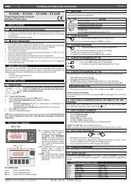
7.3 XW60L: MOUNTING<br />
6.2 GENERIC ALARM (I2F = EAL)<br />
As soon as the digital input is activated the unit will wait for “did” time delay before signalling the “EAL” alarm<br />
message. The outputs status don’t change. The alarm stops just after the digital input is de-activated.<br />
6.3 SERIOUS ALARM MODE (I2F = BAL)<br />
When the digital input is activated, the unit will wait for “did” delay before signalling the “BAL” alarm message.<br />
The relay outputs are switched OFF. The alarm will stop as soon as the digital input is de-activated.<br />
2<br />
1<br />
6.4 PRESSURE SWITCH (I2F = PAL)<br />
If during the interval time set by “did” parameter, the pressure switch has reached the number of activation of the<br />
“nPS” parameter, the “PAL” pressure alarm message will be displayed. The compressor and the regulation are<br />
stopped. When the digital input is ON the compressor is always OFF.<br />
If the nPS activation in the did time is reached, switch off and on the instrument to restart normal<br />
regulation.<br />
4<br />
3<br />
6.5 START DEFROST (I2F = DFR)<br />
It executes a defrost if there are the right conditions. After the defrost is finished, the normal regulation will restart<br />
only if the digital input is disabled otherwise the instrument will wait until the “Mdf” safety time is expired.<br />
6.6 ENERGY SAVING (I2F = ES)<br />
The Energy Saving function allows to change the set point value as the result of the SET+ HES (parmeter) sum.<br />
This function is enabled until the digital input is activated.<br />
6.7 REMOTE ON/OFF (I2F = ONF)<br />
This function allows to switch ON and OFF the instrument.<br />
4<br />
3<br />
2<br />
1<br />
RG-LX gascke<br />
(optional)<br />
6.8 DIGITAL INPUTS POLARITY<br />
The digital input polarity depends on the “I2P” parameters.<br />
CL : the digital input is activated by closing the contact.<br />
OP : the digital input is activated by opening the contact<br />
7. INSTALLATION AND MOUNTING<br />
Instruments XW60L shall be mounted on vertical panel, in a 150x31 mm hole, and fixed using two screws ∅ 3 x<br />
2mm. To obtain an IP65 protection grade use the front panel rubber gasket (mod. RG-L).<br />
Instruments XW60V shall be mounted on vertical panel, in a 72x56 mm hole, and fixed using screws ∅ 3 x 2mm.<br />
To obtain an IP65 protection grade use the front panel rubber gasket (mod. RGW-V).<br />
The temperature range allowed for correct operation is 0 - 60 °C. Avoid places subject to strong vibrations,<br />
corrosive gases, excessive dirt or humidity. The same recommendations apply to probes. Let the air circulate by<br />
the cooling holes.<br />
7.1 XW60V: CUT OUT<br />
8. ELECTRICAL CONNECTIONS<br />
The instruments are provided with screw terminal block to connect cables with a cross section up to 2,5 mm 2 for<br />
the digital and analogue inputs. Relays and power supply have a Faston connection (6,3mm). Heat-resistant<br />
cables have to be used. Before connecting cables make sure the power supply complies with the instrument’s<br />
requirements. Separate the probe cables from the power supply cables, from the outputs and the power<br />
connections. Do not exceed the maximum current allowed on each relay, in case of heavier loads use a suitable<br />
external relay.<br />
N.B. Maximum current allowed for all the loads is 20A.<br />
8.1 PROBE CONNECTIONS<br />
The probes shall be mounted with the bulb upwards to prevent damages due to casual liquid infiltration. It is<br />
recommended to place the thermostat probe away from air streams to correctly measure the average room<br />
temperature. Place the defrost termination probe among the evaporator fins in the coldest place, where most ice is<br />
formed, far from heaters or from the warmest place during defrost, to prevent premature defrost termination.<br />
56<br />
9. USE OF THE PROGRAMMING “HOT KEY “<br />
The Wing units can UPLOAD or DOWNLOAD the parameter list from its own E2 internal memory to the “Hot<br />
Key” and vice-versa.<br />
7.2 XW60L: CUT OUT<br />
+0.5<br />
31<br />
Ø3 x2<br />
40<br />
165<br />
150<br />
+1<br />
-1<br />
+0.5<br />
-0<br />
9.1 DOWNLOAD (FROM THE “HOT KEY” TO THE INSTRUMENT)<br />
1. Turn OFF the instrument by means of the ON/OFF key, remove the TTL serial cable if present, insert the<br />
“Hot Key” and then turn the Wing ON.<br />
2. Automatically the parameter list of the “Hot Key” is downloaded into the Wing memory, the “DoL”<br />
message is blinking. After 10 seconds the instrument will restart working with the new parameters.<br />
3. Turn OFF the instrument remove the “Hot Key”, plug in the TTL serial cable, then turn it ON again.<br />
At the end of the data transfer phase the instrument displays the following messages:<br />
“end “ for right programming. The instrument starts regularly with the new programming.<br />
“err” for failed programming. In this case turn the unit off and then on if you want to restart the download again or<br />
remove the “Hot key” to abort the operation.<br />
9.2 UPLOAD (FROM THE INSTRUMENT TO THE “HOT KEY”)<br />
1. Turn OFF the instrument by means of the ON/OFF key and remove the TTL serial cable if present; then<br />
turn it ON again.<br />
2. When the Wing unit is ON, insert the “Hot key” and push 9 key; the "uPL" message appears.<br />
3. Push “SET” key to start the UPLOAD; the “uPL” message is blinking.<br />
4. Turn OFF the instrument remove the “Hot Key”, plug in the TTL serial cable, then turn it ON again.<br />
At the end of the data transfer phase the instrument displays the following messages:<br />
“end “ for right programming.<br />
“err” for failed programming. In this case push “SET” key if you want to restart the programming again or remove<br />
the not programmed “Hot key”.<br />
1592009267 XW60L-V GB r1.0 15.12.2004.doc ;:/ ² ;:9 3/4
,QVWDOOLQJ DQG 2SHUDWLQJ ,QVWUXFWLRQV UHO FRG <br />
10. ALARM SIGNALS<br />
Message Cause Outputs<br />
“P1” Thermostat probe failure Alarm output ON; Compressor output according to<br />
parameters “COn” and “COF”<br />
“P2” Evaporator probe failure Alarm output ON; Other outputs unchanged<br />
“HA” Maximum temperature alarm Alarm output ON; Other outputs unchanged<br />
“LA” Minimum temperature alarm Alarm output ON; Other outputs unchanged<br />
“EE” Data or memory failure Alarm output ON; Other outputs unchanged<br />
“dA” Door switch alarm Alarm output ON; Other outputs unchanged<br />
“EAL” External alarm Alarm output ON; Other outputs unchanged<br />
“BAL” Serious external alarm Alarm output ON; Other outputs OFF<br />
“PAL” Pressure switch alarm Alarm output ON; Other outputs OFF<br />
The alarm message is displayed until the alarm condition is recovery.<br />
All the alarm messages are showed alternating with the room temperature except for the “P1” which is flashing. To<br />
reset the “EE” alarm and restart the normal functioning press any key, the “rSt” message is displayed for about 3s.<br />
10.1 SILENCING BUZZER<br />
Once the alarm signal is detected the buzzer can be silenced by pressing any key.<br />
10.2 “EE” ALARM<br />
The instruments are provided with an internal check for the data integrity. Alarm “EE” flashes when a<br />
failure in the memory data occurs. In such cases the alarm output is enabled.<br />
10.3 ALARM RECOVERY<br />
Probe alarms : “P1” (probe1 faulty), “P2” ; they automatically stop 10s after the probe restarts normal operation.<br />
Check connections before replacing the probe.<br />
Temperature alarms “HA” and “LA” automatically stop as soon as the thermostat temperature returns to normal<br />
values or when the defrost starts.<br />
Door switch alarm “dA” stop as soon as the door is closed.<br />
External alarms “EAL”, “BAL” stop as soon as the external digital input is disabled<br />
Pressure switch alarm “PAL” alarm is recovered by switching OFF the instrument.<br />
11. TECHNICAL DATA<br />
Housing: self extinguishing ABS.<br />
Case<br />
XW60L: facia 38x185 mm; depth 76mm<br />
XW60V: facia 100x64 mm; depth 76mm<br />
Mounting<br />
XW60L: panel mounting in a 150x31 mm panel cut-out with two screws. ∅ 3 x 2mm. Distance between the holes<br />
165mm<br />
XW60L: panel mounting in a 56x72 mm panel cut-out with two screws. ∅ 3x2mm. Distance between the<br />
holes 40mm<br />
Protection: IP20.<br />
Frontal protection: IP65 with optional frontal gasket mod RG-L (XW60L); RGW-V (XW60V).<br />
Connections: Screw terminal block ≤ 2,5 mm 2 heat-resistant wiring and 6,3mm Faston<br />
Power supply: 230Vac or. 110Vac ± 10%<br />
Power absorption: 7VA max.<br />
Display: 3 digits, red LED, 14,2 mm high.<br />
Inputs: 2 NTC or PTC probes<br />
Digital input: 1 free voltage<br />
Relay outputs: Total current on loads MAX. 20A<br />
compressor: relay SPST 20(8) A, 250Vac or. SPST 8(3) A, 250Vac<br />
light: XW60L: relè SPDT 8(3) A, 250Vac; XW60V: relè SPST 16(6) A, 250Vac<br />
fans: relay SPST 8(3) A, 250Vac<br />
defrost: relay SPST 8(3) A, 250Vac<br />
Other output : alarm buzzer<br />
Data storing: on the non-volatile memory (EEPROM).<br />
Kind of action: 1B.<br />
Pollution grade: normal<br />
Software class: A.<br />
Operating temperature: 0÷60 °C.<br />
Storage temperature: -25÷60 °C.<br />
Relative humidity: 20÷85% (no condensing)<br />
Measuring and regulation range:<br />
PTC probe: -50÷150°C (-58÷302°F)<br />
NTC probe: -40÷110°C (-58÷230°F)<br />
Resolution: 0,1 °C or 1°C or 1 °F (selectable).<br />
Accuracy (ambient temp. 25°C): ±0,5 °C ±1 digit<br />
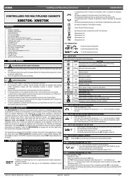
12. CONNECTIONS<br />
8A<br />
250Vac<br />
8A<br />
250Vac<br />
Fan<br />
8A<br />
250Vac<br />
Def.<br />
20A<br />
250Vac<br />
Comp<br />
Line<br />
Neutral<br />
MAX<br />
20A<br />
<br />
Luce<br />
Digital inp.<br />
Def. Room<br />
Probe Probe<br />
XW60L<br />
16A<br />
250Vac<br />
<br />
Light<br />
13. DEFAULT SETTING VALUES<br />
Room<br />
Probe<br />
Fan<br />
Evap.<br />
Probe<br />
<br />
8A<br />
250Vac<br />
8A<br />
250Vac<br />
N.C.<br />
Def.<br />
Digital<br />
Input<br />
XW60V<br />
20A<br />
250Vac<br />
<br />
Comp<br />
Line<br />
Neutral<br />
MAX<br />
20A<br />
Label Name Range Default Level<br />
REGULATION<br />
Set Set point LS÷US -5/0 Pr1<br />
Hy Differential 0,1÷25,5 °C / 1÷45°F 2/4 Pr1<br />
LS Minimum set point -50,0°C÷SET / -58°F÷SET -30/-22 Pr2<br />
US Maximum set point SET ÷ 110°C / SET ÷ 230°F 20/68 Pr2<br />
OdS Outputs activation delay at start up 0÷255 min. 0 Pr2<br />
AC Anti-short cycle delay 0÷30 min. 1 Pr1<br />
CCt Compressor ON time during fast freezing 0 ÷ 23h 50 min. 0.0 Pr2<br />
COn Compressor ON time with faulty probe 0÷255 min. 15 Pr2<br />
COF Compressor OFF time with faulty probe 0÷255 min. 30 Pr2<br />
DISPLAY<br />
CF Temperature measurement unit °C ÷ °F °C/F Pr2<br />
rES Resolution (integer/decimal point) in ÷ de dE/- Pr1<br />
Lod Local display P1 ÷ 1r2 P1 Pr2<br />
DEFROST<br />
tdF Defrost type rE, rT, in rE Pr2<br />
EdF Defrost mode In, Sd in Pr2<br />
SdF Set point for SMART DEFROST -30 ÷ +30°C / -22÷+86°F 0/32 Pr2<br />
dtE Defrost termination temperature -50,0÷110°C/ -58÷230°F 8/46 Pr1<br />
IdF Interval between defrost cycles 1÷120h 6 Pr1<br />
MdF (Maximum) length for 1° defrost 0÷255 min. 30 Pr1<br />
dFd Displaying during defrost rt, it, SEt, dEF, dEG it Pr2<br />
dAd MAX display delay after defrost 0÷255 min. 30 Pr2<br />
dSd Delay before defrost 0÷255 min. 0 Pr2<br />
Fdt Draining time 0÷60 min. 0 Pr2<br />
dPO First defrost after start up n ÷ y n Pr2<br />
dAF Defrost delay after fast freezing 0 ÷ 23h 50 min. 0.0 Pr2<br />
FANS<br />
FnC Fans operating mode C-n, C-y, O-n, O-y O-n Pr2<br />
Fnd Fans delay after defrost 0÷255 min. 10 Pr2<br />
FSt Fans stop temperature -50,0÷110°C/ -58÷230°F 2/36 Pr2<br />
ALARMS<br />
ALC Temperature alarms configuration rE÷Ab Ab Pr2<br />
ALU MAXIMUM temperature alarm -50,0÷110°C/ -58÷230°F 110/230 Pr1<br />
ALL minimum temperature alarm -50,0÷110°C/ -58÷230°F -40/-40 Pr1<br />
AFH Temperature alarm differential 0,1÷25,5 °C / 1÷45°F 2/4 Pr2<br />
ALd Temperature alarm delay 0÷255 min. 15 Pr2<br />
dAO Delay of temperature alarm at start up 0 ÷ 23h 50 min. 1,3 Pr2<br />
EdA Alarm delay at the end of defrost 0÷255 min. 30 Pr2<br />
dot Delay of temperature alarm after closing the door 0÷255 min. 15 Pr2<br />
dOA Open door alarm delay 0÷255 min. 15 Pr2<br />
nPS Pressure switch number 0÷15 0 Pr2<br />
ANALOGUE INPUTS<br />
Ot Thermostat probe calibration -12,0÷12,0°C / -21÷21°F 0 Pr1<br />
OE Evaporator probe calibration -12,0÷12,0°C / -21÷21°F 0 Pr2<br />
P2P Evaporator probe presence n ÷ y y Pr2<br />
HES Temperature increasing during the Energy Saving -30÷30°F/-54÷54°F 0 Pr2<br />
cycle<br />
DIGITAL INPUTS<br />
Odc Open door control no, Fan, CPr, F_C Fan Pr2<br />
I2P Configurable digital input polarity CL÷OP CL Pr2<br />
i2F Digital input configuration dor, EAL, bAL, PAL, dFr, dor Pr2<br />
AUS, ES, OnF<br />
dId Digital input alarm delay 0÷255 min. 5 Pr2<br />
OTHER<br />
Pbc Kind of probe PbC, ntc ntc/Ptc Pr2<br />
rEL Software release - - - 2.0 Pr2<br />
Ptb Map code - - - - - - Pr2<br />
Prd Probes display Pb1÷Pb3 - - - Pr2<br />
Pr2 Access parameter list - - - - - - Pr1<br />
Dixell S.p.A. Via dell’Industria, 27<br />
32010 Z.I Pieve d’Alpago (BL) ITALY<br />
tel. +39 - 0437 - 98 33 - fax +39 - 0437 - 98 93 13<br />
(PDLOGL[HOO#GL[HOOFRP KWWSZZZGL[HOOFRP<br />
1592009267 XW60L-V GB r1.0 15.12.2004.doc ;:/ ² ;:9 4/4