LZ100 Command Station - Lenz USA
LZ100 Command Station - Lenz USA
LZ100 Command Station - Lenz USA

Create successful ePaper yourself
Turn your PDF publications into a flip-book with our unique Google optimized e-Paper software.
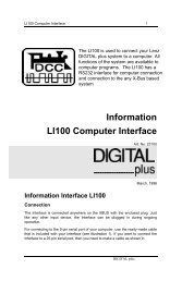
<strong>Command</strong> <strong>Station</strong> <strong>LZ100</strong> 1<br />
Unleashing the<br />
Power of DCC<br />
<strong>LZ100</strong> <strong>Command</strong> <strong>Station</strong><br />
Operations Manual<br />
Version 3.2<br />
art. no. 20101<br />
revised February 2001<br />
Version 3.2<br />
DIGITAL plus
2 <strong>Command</strong> <strong>Station</strong> <strong>LZ100</strong><br />
Getting started<br />
To get started with DIGITAL plus, you need:<br />
• <strong>Command</strong> <strong>Station</strong> <strong>LZ100</strong><br />
• Hand Held Controller LH100, LH200 or other certified<br />
XpressNET handheld<br />
• Power <strong>Station</strong> LV101 or LV200<br />
• Locomotive equipped with a DIGITAL plus locomotive<br />
decoder, or with another NMRA-DCC compatible locomotive<br />
decoder<br />
• Suitable transformer for your power station (see power<br />
station manual for details)<br />
• Transformer providing 18VA at 14-16 volts AC for <strong>LZ100</strong><br />
(part# TR16 or suitable substitute)<br />
The DIGITAL plus units have removable multi-pin connectors<br />
with screw terminals, to make connecting wires easy.<br />
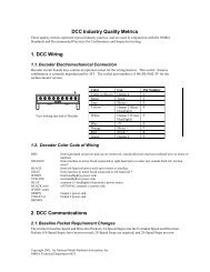
System architecture of DIGITAL plus<br />
Your <strong>LZ100</strong> is the central hub in your DIGITAl plus system.<br />
DIGITAL plus is a digital multi-train control system for all model<br />
railroad scales. It was developed in close cooperation with model<br />
railroaders. Figure 1 shows the simple and clear system design<br />
of DIGITAL plus.<br />
DIGITAL plus is compatible with NMRA-DCC systems and their<br />
locomotive and accessory decoders. It is also compatible with all<br />
XpressNet certified handhelds or other system devices. If you<br />
have an older NMRA DCC system, you can use this older<br />
system as a handheld using the Translation Module LC100.<br />
The capabilities of DIGITAL plus are to a large extent<br />
determined by a program running inside the unit, the software.<br />
Version 3.0 is our 4 th major system release.<br />
The advantage of this approach is that new functions can be<br />
adopted simply by changing the software. It is not necessary to<br />
purchase new units. This way it is easier to implement<br />
suggestions for improvements from model railroaders.<br />
DIGITAL plus
<strong>Command</strong> <strong>Station</strong> <strong>LZ100</strong> 3<br />
Figure 1: DIGITAL plus System Overview<br />
<strong>Command</strong> <strong>Station</strong> <strong>LZ100</strong><br />
The core of the system is the <strong>LZ100</strong> <strong>Command</strong> <strong>Station</strong>. The<br />
<strong>LZ100</strong> coordinates the input devices (Hand Held Controller<br />
LH100, etc.) and is also responsible for data processing.<br />
Information is exchanged between <strong>Command</strong> <strong>Station</strong> and input<br />
devices via a 4-wire cable, called XpressNet. The <strong>Command</strong><br />
<strong>Station</strong> generates the control signals for Power <strong>Station</strong><br />
LV101/LV200, which combines them with the necessary power<br />
and sends them to locomotive and accessory decoders.<br />
The <strong>Command</strong> <strong>Station</strong> has no boosted output to connect to<br />
tracks. Accordingly it only needs a small transformer 14-16V AC<br />
(18VA), which could be one you already have from a starter set<br />
or supplied as part number TR16.<br />
DIGITAL plus
4 <strong>Command</strong> <strong>Station</strong> <strong>LZ100</strong><br />
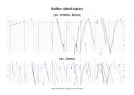
Installing the <strong>Command</strong> <strong>Station</strong><br />
<strong>Command</strong> <strong>Station</strong> <strong>LZ100</strong> is connected to the AC output of the<br />
transformer with 2 wires at terminals U and V (see Figure 2). For<br />
long-term operation you need a separate transformer such as<br />
the TR16.<br />
Figure 2: Complete Connections of <strong>Command</strong> <strong>Station</strong> and<br />
Power <strong>Station</strong><br />
Connect the programming track to terminals P and Q. This track<br />
must be completely isolated from the rest of the layout.<br />
Terminals C and D transmit the data signal needed by the Power<br />
<strong>Station</strong>. These terminals are connected with the corresponding<br />
terminals on the Power <strong>Station</strong> with a twisted pair wire (see<br />
Figure 2). You can easily make a twisted pair wire from two<br />
normal single wires that you twist together.<br />
The terminal E connection between the <strong>LZ100</strong> and the LV101 is<br />
optional. If terminal E on the <strong>Command</strong> <strong>Station</strong> is connected to<br />
terminal E on the Power <strong>Station</strong>, the Power <strong>Station</strong> is able to<br />
provide feedback about overloads. The <strong>Command</strong> <strong>Station</strong> will<br />
then turn off all other Power <strong>Station</strong>s and send the<br />
corresponding information to Hand Held Controllers and other<br />
input devices. You can also use a pushbutton to connect<br />
terminal E to connection M. This allows the push button to be<br />
used as a layout emergency stop.<br />
DIGITAL plus
<strong>Command</strong> <strong>Station</strong> <strong>LZ100</strong> 5<br />
The feedback bus is connected at terminals R and S. Via this<br />
wire, which also must be a twisted pair, the <strong>Command</strong> <strong>Station</strong><br />
asks for the state of for example turnouts or track occupancy<br />
detectors. For this purpose, feedback units are connected to this<br />
(Accessory Decoder with Feedback LS100 or Feedback Encoder<br />
LR101). For more details on connecting these units, please refer<br />
to the respective manuals.<br />
If the <strong>Command</strong> <strong>Station</strong> is correctly installed and wired, and the<br />
supply power of the transformer switched on, the LED on the<br />
front of the <strong>Command</strong> <strong>Station</strong> lights up. If the LED flashes after<br />
the power up, then there is a wiring problem on the XpressNet.<br />
The <strong>LZ100</strong> XpressNet<br />
The connecting wires from <strong>Command</strong> <strong>Station</strong> <strong>LZ100</strong> to the input<br />
units, (for instance Hand Held Controller LH100, LH200, or the<br />
Interface), are referred to as the XpressNet. Via this computer<br />
network, the <strong>Command</strong> <strong>Station</strong> and connected devices<br />
exchange information.<br />
XpressNet is an open protocol and uses the industry standard<br />
RS-485 for communication. Any certified XpressNet device can<br />
be used with your <strong>LZ100</strong><br />
A maximum of 30 devices are allowed on XpressNet. Each of<br />
the connected units has its own address, so that data exchange<br />
is problem-free. Directions for how to change the address of<br />
Hand Held Controller LH100 or another input device on<br />
XpressNet are found in the corresponding manuals.<br />
DIGITAL plus
6 <strong>Command</strong> <strong>Station</strong> <strong>LZ100</strong><br />
The XpressNet can be connected to the <strong>Command</strong> <strong>Station</strong> via<br />
either a 5-pin DIN connector or terminals L, M, A and B. You<br />
can connect the first Hand Held Controller directly to the 5-pin<br />
DIN connector on <strong>Command</strong> <strong>Station</strong> <strong>LZ100</strong>.<br />
If you want to connect additional Hand Held Controller<br />
LH100/LH200 (or other input devices) to your <strong>LZ100</strong> <strong>Command</strong><br />
<strong>Station</strong>, then you use terminals L, M, A and B. Via the wires at<br />
terminals A and B, the units exchange data with the <strong>Command</strong><br />
<strong>Station</strong>. Via the wires at terminals L (plus) and M (minus) the<br />
units are supplied with power.<br />
You can extend your XpressNet using LA150 or LA152 adaptor<br />
boards or solder the 4 wires to the DIN-sockets yourself.<br />
Using 5 pin Din Plugs<br />
The most reliable long-term instillation is to use 5 pin Din plugs.<br />
These can be obtained from most electronic parts stores or<br />
through your <strong>Lenz</strong> dealer in groups of five as part XP-5.<br />
The assignment of the five-pin DIN-socket is shown in the<br />
following figure:<br />
Connection Board LA150 21150<br />
Pin Assignments from solder side<br />
Make sure that you do not mix up the cables of the<br />
terminals L and M. This could result in a short in the<br />
connected input devices.<br />
If you are upgrading from a Set-02 you may replace the coil cord<br />
on the LH200 you used as the command station with a coil cord<br />
that has a 5-pin din connector. The DIGITAL plus part number<br />
for the cord is LY006<br />
DIGITAL plus
<strong>Command</strong> <strong>Station</strong> <strong>LZ100</strong> 7<br />
Using Modular Plugs<br />
You may use Module plugs instead of DIN plugs for wiring your<br />
XpressNet or any combination of Din and Module plugs.<br />
Pin # Port A Port B Description<br />
Pin 1 White N/C Not used<br />
Pin 2 Black Black Ground "M"<br />
Pin 3 Red Red - RS-485 "B"<br />
Pin 4 Green Green + RS-485 "A"<br />
Pin 5 Yellow Yellow +12 volts "L"<br />
Pin 6 Blue N/C Not Used<br />
If you use module plugs you can use either 4 or 6 wire plugs.<br />
Note: If you are upgrading from Set-02 you must remove the<br />
module plug connection to your LV101 or LV200 and instead<br />
connect your LH200 to the <strong>LZ100</strong>'s XpressNet.<br />
DIGITAL plus
8 <strong>Command</strong> <strong>Station</strong> <strong>LZ100</strong><br />
Using the LA152<br />
To use the LA152 with an <strong>LZ100</strong> simply connect the LMAB<br />
outputs on the rear of the <strong>LZ100</strong> to the corresponding LMAB<br />
connection on the rear of the LA152. Additional LA152 adapters<br />
can then be connected using either four wire RJ14 or 6 wire<br />
RJ12 cables.<br />
Using Multiple LA152s<br />
You can install any combination of LA152 and or DIN sockets<br />
around your layout that you like.<br />
When interconnecting LA152s you can use either RJ11 4 wire<br />
cable or RJ12 6 wire cable to connect Port A of one LA152 to<br />
Port A of another LA152.<br />
Note: Care must be taken to use reverse style modular phone<br />
cables (see above figure) to interconnect LA152s<br />
DIGITAL plus
<strong>Command</strong> <strong>Station</strong> <strong>LZ100</strong> 9<br />
XpressNet Wiring<br />
The XpressNet wiring must be installed so that the line starts at<br />
the <strong>Command</strong> <strong>Station</strong> and ends somewhere on your layout.<br />
(Daisy chained from <strong>Command</strong> <strong>Station</strong> via intermediate input<br />
locations to the last input location.) Between the start and end<br />
you may insert connecting panels or 5-pin DIN connectors<br />
anywhere. You must not route the wire as a closed loop. Under<br />
all circumstances you must ensure that either phone cables are<br />
used or the wires that are connected to terminals A and B are<br />
twisted.<br />
When wiring the X-BUS, wires must not be allowed to loop<br />
The ends of the XpressNet Network lines A and B should be<br />
connected to the resistor, which is enclosed with the <strong>LZ100</strong>. The<br />
resistor has a value of 120 Ohm.<br />
Terminating the XpressNET with a resistor<br />
Which cable is to be used for the XpressNET<br />
The minimum gauge of the wire in the XpressNet should be 24<br />
gauge. In practice so-called "bell wire" has proved efficient. This<br />
can be acquired cheaply. It is sufficiently twisted and available in<br />
various colors. If you are using LA152 adaptors then common 6<br />
wire phone cables can be used.<br />
How long may an XpressNET network be<br />
For reasons of physics the maximum length of the XpressNet<br />
depends on the kind and size of the wires used for the<br />
XpressNet. With normal telephone wire the length should not<br />
exceed 300 ft. If you install a twin-core, twisted cable for the<br />
signal lines of the XpressNet you can increase the length to up<br />
to 3000 ft. without problems.<br />
DIGITAL plus
10 <strong>Command</strong> <strong>Station</strong> <strong>LZ100</strong><br />
Configuring the <strong>LZ100</strong><br />
There are several settings that can be configured on the <strong>LZ100</strong>.<br />
These settings can be activated from any XpressNet handheld.<br />
System Reset<br />
If you experience problems with your <strong>LZ100</strong> or wish to reset it to<br />
factory default setting you may perform the following operation<br />
1) Set your handheld to operate locomotive 00 (the analog<br />
locomotive) and bring that locomotive to a stop<br />
2) Press the F4 key 25 times in succession. You may notice<br />
that after the 20 th time that a brief power interruption occurs<br />
on the layout.<br />
3) Remove power from the <strong>LZ100</strong>. When you next power up<br />
the system all memory will be returned to factory default<br />
settings.<br />
Note all memory including knowledge of consists will be removed<br />
from the <strong>LZ100</strong> memory when you perform a reset operation.<br />
Auto mode/Manual Mode<br />
The LZ10 has two modes of operation. In manual mode (the<br />
default) the <strong>LZ100</strong> activates all the functions that were on when<br />
the <strong>LZ100</strong> was last shut down. In automatic operation the speed<br />
and direction of all locomotives are also returned to what they<br />
were when the <strong>LZ100</strong> was last powered down.<br />
To reconfigure the <strong>LZ100</strong> for automatic operation perform the<br />
following operation<br />
1) Set your handheld to operate locomotive 00 (the analog<br />
locomotive) and bring that locomotive to a stop<br />
2) Press the F1 key approximately 5 times till the LED on the<br />
front of the <strong>LZ100</strong> turns off and than continue pressing the<br />
F1 key till the <strong>LZ100</strong> LED turns on again.<br />
DIGITAL plus
<strong>Command</strong> <strong>Station</strong> <strong>LZ100</strong> 11<br />
To return the <strong>LZ100</strong> to manual operation perform the following<br />
operation<br />
1) Set your handheld to operate locomotive 00 (the analog<br />
locomotive) and bring that locomotive to a stop<br />
2) Press the F2 key approximately 5 times till the LED on the<br />
front of the <strong>LZ100</strong> turns off and than continue pressing the<br />
F2 key till the <strong>LZ100</strong> LED turns on again.<br />
North American Warranty<br />
<strong>Lenz</strong> GmbH does everything it can do to ensure that its products<br />
are free from defects and will operate for the life of your model<br />
railroad equipment. From time to time even the best-engineered<br />
products fail either due to a faulty part or from accidental<br />
mistakes in installation. To protect your investment in Digital<br />
Plus products, <strong>Lenz</strong> GmbH offers a very aggressive 10 year<br />
Limited Warranty.<br />
This warranty is not valid if the user has altered, intentionally<br />
misused the Digital Plus product, or removed the product's<br />
protection, for example the heat shrink from decoders and other<br />
devices. In this case a service charge will be applied for all<br />
repairs or replacements. Should the user desire to alter a Digital<br />
Plus Product; they should contact <strong>Lenz</strong> GmbH for prior<br />
authorization.<br />
Year One: A full repair or replacement will be provided to the<br />
original purchaser for any item that that has failed due to<br />
manufacturer defects or failures caused by accidental user<br />
installation problems. Should the item no longer be produced<br />
and the item is not repairable, a similar item will be substituted at<br />
the manufacturers discretion. The user must pay for shipping to<br />
an authorized <strong>Lenz</strong> GmbH warranty center.<br />
Year 2 and 3: A full replacement for any item will be provided<br />
that has failed due to manufacturer defects. If the failure was<br />
caused by accidental user installation or use, a minimal service<br />
charge may be imposed. Should the item no longer be produced<br />
and the item is not repairable, a similar item will be substituted at<br />
the manufacturers discretion. The user must pay shipping to<br />
and from the authorized <strong>Lenz</strong> GmbH warranty center during this<br />
portion of the warranty period.<br />
DIGITAL plus
12 <strong>Command</strong> <strong>Station</strong> <strong>LZ100</strong><br />
Year 4-10: A minimal service charge will be placed on each<br />
item that has failed due to manufacturer defects and/or<br />
accidental user installation problems. Should the item no longer<br />
be produced and the item is not repairable, a similar item will be<br />
substituted at the manufacturers discretion. The user must pay<br />
shipping to and from the authorized <strong>Lenz</strong> GmbH warranty center<br />
during this portion of the warranty period.<br />
Please contact your dealer or authorized <strong>Lenz</strong> GmbH warranty<br />
center for specific instructions and current service charges prior to<br />
returning any equipment for repair.<br />
Hüttenbergstrasse 29<br />
35398 Giessen<br />
Germany<br />
Hotline: 06403 900 133<br />
Fax: 06403 900 155<br />
info@digital-plus.de<br />
<strong>Lenz</strong> Agency of North America<br />
PO Box 143<br />
Chelmsford, MA 01824 <strong>USA</strong><br />
Phone: 978 250 1494<br />
Fax: 978 455 LENZ<br />
support@lenz.com<br />
www.lenz.com<br />
This equipment complies with Part 15 of FCC Rules. Operation is subject<br />
to the following two conditions: (1) this device may not cause harmful interference,<br />
and (2) this device must accept any interference received, including interference<br />
that may cause undesired operation.<br />
Please save this manual for future reference!<br />
© 2001 <strong>Lenz</strong> GmbH, All Rights Reserved<br />
DIGITAL plus