Manual thermoMETER CT (PDF, 1.24 MB) - Micro-Epsilon
Manual thermoMETER CT (PDF, 1.24 MB) - Micro-Epsilon
Manual thermoMETER CT (PDF, 1.24 MB) - Micro-Epsilon

Create successful ePaper yourself
Turn your PDF publications into a flip-book with our unique Google optimized e-Paper software.
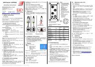
Instruction <strong>Manual</strong><br />
<strong>thermoMETER</strong> <strong>CT</strong><br />
<strong>CT</strong>F<br />
<strong>CT</strong>H<br />
<strong>CT</strong>P<br />
<strong>CT</strong>M-1<br />
<strong>CT</strong>M-2<br />
<strong>CT</strong>M-3
Infrared sensor<br />
MICRO-EPSILON<br />
MESSTECHNIK<br />
GmbH & Co. KG<br />
Königbacher Strasse 15<br />
94496 Ortenburg / Germany<br />
Tel. +49 (0) 8542 / 168-0<br />
Fax +49 (0) 8542 / 168-90<br />
e-mail info@micro-epsilon.de<br />
www.micro-epsilon.com<br />
Certified acc. to DIN EN ISO 9001: 2008
Contents<br />
1. Safety......................................................................................................................................... 7<br />
1.1 Symbols Used.................................................................................................................................................. 7<br />
1.2 Warnings........................................................................................................................................................... 7<br />
1.3 Notes on CE Identification................................................................................................................................ 8<br />
1.4 Proper Use........................................................................................................................................................ 9<br />
1.5 Proper Environment.......................................................................................................................................... 9<br />
2. Technical Data......................................................................................................................... 10<br />
2.1 Functional Principle........................................................................................................................................ 10<br />
2.2 Sensor Models................................................................................................................................................ 11<br />
2.3 General Specifications.................................................................................................................................... 12<br />
2.4 Electrical Specifications.................................................................................................................................. 13<br />
2.5 Measurement Specifications ......................................................................................................................... 14<br />
2.5.1 <strong>CT</strong> Model....................................................................................................................................... 14<br />
2.5.2 <strong>CT</strong>F / <strong>CT</strong>H Models......................................................................................................................... 15<br />
2.5.3 <strong>CT</strong>M / <strong>CT</strong>P Models........................................................................................................................ 16<br />
3. Delivery.................................................................................................................................... 19<br />
3.1 Unpacking....................................................................................................................................................... 19<br />
3.2 Storage........................................................................................................................................................... 19<br />
4. Optical Charts.......................................................................................................................... 20<br />
5. CF Lens and Protective Window............................................................................................ 28<br />
6. Mechanical Installation........................................................................................................... 31<br />
6.1 Mounting Accessories.................................................................................................................................... 33<br />
6.2 Air Purge Collars............................................................................................................................................. 34<br />
6.2.1 Standard Air Purge Collar............................................................................................................. 34<br />
6.2.2 Laminar Air Purge Collar............................................................................................................... 35<br />
<strong>thermoMETER</strong> <strong>CT</strong>
6.3 Further Accessories........................................................................................................................................ 36<br />
6.3.1 Right Angle Mirror......................................................................................................................... 36<br />
6.3.2 Rail Mount Adapter for Controller................................................................................................. 37<br />
6.3.3 Tilt Assembly for <strong>CT</strong> Sensors........................................................................................................ 37<br />
6.3.4 Laser Sighting Tool........................................................................................................................ 38<br />
6.3.5 OEM Laser Sighting Tool............................................................................................................... 39<br />
6.3.6 Massive Housing........................................................................................................................... 40<br />
6.3.7 Accessories for Massive Housing................................................................................................. 41<br />
6.3.8 Pipe Adapter and Sighting Tubes................................................................................................. 42<br />
7. Electrical Installation............................................................................................................... 43<br />
7.1 Cable Connections......................................................................................................................................... 43<br />
7.1.1 Pin Assignment.............................................................................................................................. 43<br />
7.1.1.1 <strong>CT</strong>-SF02, <strong>CT</strong>-SF15, <strong>CT</strong>-SF22, <strong>CT</strong>F-SF15, <strong>CT</strong>F-SF25, <strong>CT</strong>H-SF02, <strong>CT</strong>H-SF10,<br />
<strong>CT</strong>P Models.................................................................................................................. 43<br />
7.1.1.2 <strong>CT</strong>M-1, <strong>CT</strong>M-2, <strong>CT</strong>M-3 Models.................................................................................... 44<br />
7.2 Power Supply.................................................................................................................................................. 44<br />
7.3 Cable Assembling........................................................................................................................................... 45<br />
7.4 Ground Connection........................................................................................................................................ 46<br />
7.5 Exchange of the Sensor................................................................................................................................. 47<br />
7.5.1 Entering of the Calibration Code................................................................................................... 47<br />
7.5.2 Sensor Cable................................................................................................................................. 48<br />
8. Outputs and Inputs.................................................................................................................. 49<br />
8.1 Analog Outputs............................................................................................................................................... 49<br />
8.1.1 Output Channel 1.......................................................................................................................... 49<br />
8.1.2 Output Channel 2 (only <strong>CT</strong>-SF02, <strong>CT</strong>-SF15, <strong>CT</strong>-SF22, <strong>CT</strong>H, <strong>CT</strong>P)............................................... 49<br />
8.2 Digital Interfaces............................................................................................................................................. 50<br />
8.2.1 USB Interface ................................................................................................................................ 51<br />
8.2.1.1 Installation.................................................................................................................... 51<br />
8.2.1.2 Driver Installation of Interface...................................................................................... 51<br />
8.2.2 RS232 Interface............................................................................................................................. 52<br />
8.2.2.1 Installation.................................................................................................................... 52<br />
8.2.2.2 Software Installation..................................................................................................... 52<br />
8.2.3 RS485 Interface............................................................................................................................. 53<br />
8.2.3.1 Installation.................................................................................................................... 53<br />
8.2.3.2 Sensor Installation........................................................................................................ 54<br />
<strong>thermoMETER</strong> <strong>CT</strong>
8.2.4 Profibus Interface.......................................................................................................................... 55<br />
8.2.4.1 Installation.................................................................................................................... 55<br />
8.2.4.2 Commissioning Profibus.............................................................................................. 56<br />
8.2.5 CAN BUS Interface........................................................................................................................ 57<br />
8.2.6 Ethernet Interface.......................................................................................................................... 59<br />
8.2.6.1 Installation.................................................................................................................... 59<br />
8.2.6.2 Installation of the Ethernet Adapter in a Network........................................................ 60<br />
8.2.6.3 Uninstalling the Ethernet Adapter in a Network........................................................... 63<br />
8.2.6.4 Direct Connection to a PC........................................................................................... 64<br />
8.2.6.5 Settings inside the CompactConnect Software........................................................... 69<br />
8.2.6.7 Resetting the Ethernet Adapter.................................................................................... 70<br />
8.3 Relays Outputs............................................................................................................................................... 71<br />
8.4 Functional Inputs............................................................................................................................................ 72<br />
8.5 Alarms............................................................................................................................................................. 73<br />
8.5.1 Output Channel 1 and 2 (Channel 2 on <strong>CT</strong>-SF / <strong>CT</strong>P).................................................................. 73<br />
8.5.2 Visual Alarms................................................................................................................................. 73<br />
9. Operating................................................................................................................................. 74<br />
9.1 Restoring Factory Setting............................................................................................................................... 74<br />
9.2 Sensor Setup.................................................................................................................................................. 76<br />
9.3 Explanation to the Menu Items....................................................................................................................... 77<br />
9.4 Error Messages............................................................................................................................................... 80<br />
9.4.1 <strong>CT</strong>-SF02, <strong>CT</strong>-SF15, <strong>CT</strong>-SF22, <strong>CT</strong>H and <strong>CT</strong>P Models.................................................................... 80<br />
9.4.2 <strong>CT</strong>M-1, <strong>CT</strong>M-2, <strong>CT</strong>M-3 Models..................................................................................................... 80<br />
10. Instructions for Operation...................................................................................................... 81<br />
10.1 Cleaning.......................................................................................................................................................... 81<br />
11. CompactConnect Software..................................................................................................... 82<br />
11.1 System Requirements.................................................................................................................................... 82<br />
11.2 Main Features................................................................................................................................................. 82<br />
12. Communication Settings........................................................................................................ 83<br />
12.1 Serial Interface................................................................................................................................................ 83<br />
12.2 Protocol........................................................................................................................................................... 83<br />
12.3 ASCII Protocol ............................................................................................................................................... 83<br />
12.4 Saving of Parameter Settings......................................................................................................................... 84<br />
<strong>thermoMETER</strong> <strong>CT</strong>
13. Basics of Infrared Thermometry............................................................................................. 85<br />
14. Emissivity................................................................................................................................. 86<br />
14.1 Definition......................................................................................................................................................... 86<br />
14.2 Determination of Unknown Emissivity............................................................................................................ 86<br />
14.3 Characteristic Emissivity................................................................................................................................. 87<br />
15. Warranty................................................................................................................................... 88<br />
16. Service, Repair........................................................................................................................ 89<br />
17. Decommissioning, Disposal................................................................................................... 89<br />
Appendix<br />
A 1 Factory Settings...................................................................................................................... 90<br />
A 2 Emissivity Table Metals........................................................................................................... 92<br />
A 3 Emissivity Table Non Metals................................................................................................... 95<br />
A 4 Smart Averaging...................................................................................................................... 97<br />
<strong>thermoMETER</strong> <strong>CT</strong>
Safety<br />
1. Safety<br />
The handling of the system assumes knowledge of the instruction manual.<br />
1.1 Symbols Used<br />
The following symbols are used in the instruction manual.<br />
Indicates a hazardous situation which, if not avoided, may result in minor or moderate<br />
injuries.<br />
Indicates a situation which, if not avoided, may lead to property damage<br />
i<br />
Measure<br />
Indicates a user action.<br />
Indicates a user tip.<br />
Indicates a hardware or a button/menu in the software<br />
1.2 Warnings<br />
Connect the power supply and the display/output device in accordance with the safety regulations for electrical<br />
equipment.<br />
> > Danger of injury<br />
> > Damage to or destruction of the sensor and/or controller<br />
Avoid shock and vibration to the sensor and the controller.<br />
> > Damage to or destruction of the sensor and/or controller<br />
The power supply must not exceed the specified limits.<br />
> > Damage to or destruction of the sensor and/or controller<br />
Protect the sensor cable against damage.<br />
> > Destruction of the sensor, Failure of the measuring device<br />
<strong>thermoMETER</strong> <strong>CT</strong><br />
Page 7
Safety<br />
Do not kink the sensor cable and bend the sensor cable in tight radius. The minimum bending radius is<br />
14 mm (static). A dynamic movement is not allowed.<br />
> > Damage to the sensor cable, failure of the measuring device<br />
No solvent-based cleaning agents may have an effect on the sensor (neither for the optics nor the housing)<br />
> > Damage to or destruction of the sensor<br />
1.3 Notes on CE Identification<br />
The following applies to the <strong>thermoMETER</strong> <strong>CT</strong>:<br />
--<br />
EU directive 2004/108/EC<br />
--<br />
EU directive 2011/65/EU, “RoHS“ category 9<br />
Products which carry the CE mark satisfy the requirements of the quoted EU directives and the European<br />
standards (EN) listed therein. The EC declaration of conformity is kept available according to EC regulation,<br />
article 10 by the authorities responsible at<br />
MICRO-EPSILON MESSTECHNIK<br />
GmbH & Co. KG<br />
Königbacher Straße 15<br />
94496 Ortenburg / Germany<br />
The system is designed for use in industry and laboratory and satisfies the requirements of the standards<br />
--<br />
EN 61326-1: 2006<br />
--<br />
EN 61326-2-3: 2006<br />
The system satisfies the requirements if they comply with the regulations described in the instruction manual<br />
for installation and operation.<br />
<strong>thermoMETER</strong> <strong>CT</strong><br />
Page 8
Safety<br />
1.4 Proper Use<br />
--<br />
The <strong>thermoMETER</strong> <strong>CT</strong> is designed for use in industrial and laboratory areas. It is used for non-contact<br />
temperature measurement.<br />
--<br />
The system may only be operated within the limits specified in the technical data, see Chap. 2..<br />
--<br />
Use the system in such a way that in case of malfunctions or failure personnel or machinery are not endangered.<br />
--<br />
Take additional precautions for safety and damage prevention for safety-related applications.<br />
1.5 Proper Environment<br />
--<br />
Protection class:<br />
• Sensor: IP 65 (NEMA 4)<br />
• Controller: IP 65 (NEMA 4)<br />
--<br />
Operating temperature:<br />
• Sensor: See also Chapter Measurement Specification, see Chap. 2.5<br />
• Controller:<br />
0 ... 85 °C (+32 ... +185 °F)<br />
Avoid abrupt changes of the operating temperature of both the sensor and the controller.<br />
> > Inaccurate measuring values<br />
--<br />
Storage temperature:<br />
• Sensor: See also Chapter Measurement Specification, see Chap. 2.5<br />
• Controller:<br />
-40 ... 85 °C (-40 ... +185 °F)<br />
--<br />
Humidity: 10 ... 95 %, non-condensing<br />
--<br />
EMC acc. to: EN 61326-1: 2006<br />
EN 61326-2-3: 2006<br />
<strong>thermoMETER</strong> <strong>CT</strong><br />
Page 9
Technical Data<br />
2. Technical Data<br />
2.1 Functional Principle<br />
The sensors of the <strong>thermoMETER</strong> <strong>CT</strong> series are non-contact measuring infrared temperature sensors. They<br />
calculate the surface temperature based on the emitted infrared energy of objects, see Chap. 13.<br />
The sensor housing of the <strong>thermoMETER</strong> <strong>CT</strong> is made from stainless steel (protection class IP 65/ NEMA 4),<br />
the controller is placed in a separate box made of die casting zinc.<br />
The <strong>thermoMETER</strong> <strong>CT</strong> sensor is a sensitive optical system. Please only use the thread for mechanical<br />
installation.<br />
i<br />
Avoid mechanical violence on the sensor.<br />
> > Destruction of the system<br />
<strong>thermoMETER</strong> <strong>CT</strong><br />
Page 10
Technical Data<br />
2.2 Sensor Models<br />
Model Model codes Measuring range Spectral response Typical applications<br />
<strong>CT</strong> <strong>CT</strong>-SF02 / <strong>CT</strong>-SF15 / -50 to 975 °C 8 - 14 μm Non-metallic surfaces<br />
<strong>CT</strong>-SF22<br />
<strong>CT</strong>F <strong>CT</strong>F-SF15 /<br />
<strong>CT</strong>F-SF25<br />
-50 to 975 °C 8 - 14 μm Fast processes<br />
<strong>CT</strong>H <strong>CT</strong>H-SF02 /<br />
<strong>CT</strong>H-SF10<br />
<strong>CT</strong>M-1SF <strong>CT</strong>M-1SF40 /<br />
<strong>CT</strong>M-1SF75 /<br />
<strong>CT</strong>M-1SF75H1<br />
<strong>CT</strong>M-2SF <strong>CT</strong>M-2SF40 /<br />
<strong>CT</strong>M-2SF75<br />
<strong>CT</strong>M-2SF75H1<br />
<strong>CT</strong>M-3SF <strong>CT</strong>M-3SF22 /<br />
<strong>CT</strong>M-3SF33 /<br />
<strong>CT</strong>M-3SF75H1 /<br />
<strong>CT</strong>M-3SF75H2 /<br />
<strong>CT</strong>M-3SF75H3<br />
-40 to 975 °C 8 - 14 μm High ambient temperatures<br />
(to 250 °C)<br />
485 to 2200 °C 1 μm Metals and ceramic surfaces<br />
250 to 2200 °C 1.6 μm Metals and ceramic surfaces<br />
50 to 1800 °C 2.3 μm Metals at low object temperatures<br />
(from 50 °C)<br />
<strong>CT</strong>P <strong>CT</strong>P 0 to 710 °C 7.9 μm Temperature of thin film<br />
plastics<br />
In the following chapters of this manual you will find only the short model codes. On the <strong>CT</strong>M-1, <strong>CT</strong>M-2 and<br />
<strong>CT</strong>M-3 models the whole measuring range is split into several sub ranges.<br />
<strong>thermoMETER</strong> <strong>CT</strong><br />
Page 11
Technical Data<br />
2.3 General Specifications<br />
<strong>thermoMETER</strong> <strong>CT</strong><br />
Sensor<br />
Protection class IP 65<br />
Operating temperature<br />
Storage temperature<br />
Relative humidity<br />
See also Chapter Measurement<br />
Specification, see Chap. 2.5<br />
See also Chapter Measurement<br />
Specification, see Chap. 2.5<br />
10 ... 95 %, non-condensing<br />
Controller<br />
0 ... 85 °C (+32 ... +185 °F)<br />
-40 ... 85 °C (-40 ... +185 °F)<br />
Material Stainless steel Die casting zinc<br />
Dimensions 28 mm x 14 mm, M12x1 89 mm x 70 mm x 30 mm<br />
Dimensions <strong>CT</strong>H, <strong>CT</strong>P<br />
55 mm x 29.5 mm, M18x1<br />
(with massive housing)<br />
89 mm x 70 mm x 30 mm<br />
Weight 40 g 420 g<br />
Cable length<br />
Cable diameter<br />
Ambient temperature<br />
cable<br />
Vibration<br />
Shock<br />
CompactConnect<br />
Software<br />
Electromagnetic<br />
compatibility (EMC)<br />
1) The <strong>CT</strong>M-3 models are only available with 3 m cable.<br />
1 m (only <strong>CT</strong>-SF02, <strong>CT</strong>-SF15, <strong>CT</strong>-SF22, <strong>CT</strong>-SF15, <strong>CT</strong>-SF22),<br />
3 m (standard at <strong>CT</strong>H, <strong>CT</strong>M 1 a nd <strong>CT</strong>P),<br />
8 m, 15 m<br />
2.8 mm<br />
Max. 180 °C<br />
[High temperature cable for CtH: 250 °C]<br />
IEC 68-2-6: 3 g 11 - 200 Hz, any axis<br />
IEC 68-2-27: 50 g, 11 ms, any axis<br />
optional<br />
EN 61326-1: 2006 and EN 61326-2-3: 2006<br />
Page 12
Technical Data<br />
2.4 Electrical Specifications<br />
Power supply<br />
Current draw<br />
Outputs/ analog<br />
Channel 1<br />
8 - 36 VDC<br />
max. 100 mA<br />
selectable: 0/4 - 20 mA, 0 - 5/10 V, thermocouple (J or K) or<br />
alarm output<br />
(Signal source: object temperature)<br />
Channel 2<br />
(only <strong>CT</strong>-SF02, <strong>CT</strong>-SF15, <strong>CT</strong>-SF22,<br />
<strong>CT</strong>P)<br />
Sensor temperature [-20 ... 180 °C], [-20 ... 250 °C at <strong>CT</strong>H-SF02 or<br />
<strong>CT</strong>H-SF10] as 0 – 5 V or 0 – 10 output or alarm output<br />
(Signal source switchable to object temperature or controller temperature<br />
if used as alarm output)<br />
Open collector Output on Pin AL2 [24 V/50 mA]<br />
Alarm output<br />
Output impedances mA max. loop resistance 500 Ω (at 8 - 36 VDC)<br />
Digital interfaces<br />
mV<br />
Thermocouple<br />
min. 100 kΩ load impedance<br />
20 Ω<br />
USB, RS232, RS485, CAN, Profibus DP, Ethernet<br />
(optional plug-in modules)<br />
Relay outputs 2 x 60 VDC/42 VAC RMS<br />
, 0.4 A;<br />
potential free (optional plug-in modules)<br />
Functional inputs<br />
F1 up to F3; software programmable for the following functions:<br />
- external emissivity adjustment<br />
--<br />
ambient temperature compensation,<br />
--<br />
trigger (reset of hold functions)<br />
Input impedance F2 and F3: 43 kΩ<br />
<strong>thermoMETER</strong> <strong>CT</strong><br />
Page 13
Technical Data<br />
2.5 Measurement Specifications<br />
<strong>thermoMETER</strong> <strong>CT</strong><br />
2.5.1 <strong>CT</strong> Model<br />
Model <strong>CT</strong>-SF02 <strong>CT</strong>-SF15 <strong>CT</strong>-SF22<br />
Temperature range (scalable) -50 ... 600 °C -50 ... 600 °C -50 ... 975 °C<br />
Operating temperature (sensor) -20 ... 130 °C -20 ...180 °C -20 ...180 °C<br />
Storage temperature (sensor) -40 ... 130 °C -20 ... 180 °C -20 ... 180 °C<br />
Spectral range<br />
8 ... 14 μm<br />
Optical resolution 2:1 15:1 22:1<br />
System accuracy 1 2 ±1 °C or ±1 % 3<br />
Repeatability 1 ±0.5 °C or ±0.5 % 3<br />
Temperature coefficient 5<br />
±0.05 K/ K or ±0.05 %/ K (whichever is greater)<br />
Temperature resolution (NETD) 3 4 0.1 K 0.05 K<br />
Response time (95 % signal)<br />
Warm-up time<br />
Emissivity/ gain<br />
Transmissivity<br />
Signal processing<br />
Software (optional)<br />
150 ms<br />
10 min<br />
0.100 ... 1.100 (adjustable via programming keys or software)<br />
0.100 ... 1.100 (adjustable via programming keys or software)<br />
Average, peak hold, valley hold<br />
(adjustable via programming keys or software)<br />
CompactConnect<br />
1) At operating temperature 23 ±5 °C; whichever is greater.<br />
2) Accuracy for thermocouple output: ±2.5 °C or ±1 %<br />
3) At object temperatures > 0 °C; e = 1<br />
4) At time constant 200 ms and an object temperature of 25 °C<br />
5) For ambient temperatures (sensor): 18 °C ≤ sensor ≤ 28 °C<br />
i<br />
On the <strong>CT</strong> models <strong>CT</strong>-SF02 the sensor cable must not be moved during the measurement.<br />
Page 14
Technical Data<br />
<strong>thermoMETER</strong> <strong>CT</strong><br />
2.5.2 <strong>CT</strong>F / <strong>CT</strong>H Models<br />
Model <strong>CT</strong>F-SF15 <strong>CT</strong>F-SF25 <strong>CT</strong>H-SF02 <strong>CT</strong>H-SF10<br />
Temperature range (scalable) -50 ... 975 °C -50 ... 975 °C -40 ... 975 °C -40 ... 975 °C<br />
Operating temperature (sensor) -20 ... 120 °C -20 ... 120 °C -20 ... 250 °C -20 ... 250 °C<br />
Storage temperature (sensor) -40 ... 120 °C -40 ... 120 °C -40 ... 250 °C -40 ... 250 °C<br />
Spectral range<br />
8 ... 14 μm<br />
Optical resolution 15:1 25:1 2:1 10:1<br />
System accuracy 1 2 ±2 °C or ±1 % 3 ±1,5 °C or ±1 % 3<br />
Repeatability 1 ±0,75 °C or ±0,75 % 3 ±0,5 °C or ±0,5 % 3<br />
Temperature coefficient 5<br />
±0.05 K/ K or ±0.05 %/ K (whichever is greater)<br />
Temperature resolution (NETD) 3 4 0.2 K 0.4 K 0.25 K 0.25 K<br />
Response time (95 % signal) 9 ms 6 ms 100 ms 100 ms<br />
Acquisition time (50 % signal) 4 ms 3 ms - -<br />
Warm-up time<br />
Emissivity / gain<br />
Transmissivity<br />
Signal processing<br />
Software (optional)<br />
10 min<br />
0.100 ... 1.100 (adjustable via programming keys or software)<br />
0.100 ... 1.100 (adjustable via programming keys or software)<br />
Average, peak hold, valley hold<br />
(adjustable via programming keys or software)<br />
CompactConnect<br />
1) At operating temperature 23 ±5 °C; whichever is greater.<br />
2) Accuracy for thermocouple output: ±2.5 °C or ±1 %<br />
3) At object temperatures ≥ 20 °C; e = 1<br />
4) At time constant 100 ms with smart averaging and an object temperature of 25 °C<br />
5) For ambient temperatures (sensor): 18 °C ≤ sensor ≤ 28 °C<br />
i<br />
On the <strong>CT</strong>H models <strong>CT</strong>H-SF02/ <strong>CT</strong>H-SF10 the sensor cable must not be moved during the measurement.<br />
Page 15
Technical Data<br />
2.5.3 <strong>CT</strong>M / <strong>CT</strong>P Models<br />
Model <strong>CT</strong>M-1SF40 <strong>CT</strong>M-1SF75 <strong>CT</strong>M-1SF75H1 <strong>CT</strong>M-2SF40<br />
Temperature range<br />
485 ... 1050 °C 650 ... 1800 °C 800 ... 2200 °C 250 ... 800 °C<br />
(scalable)<br />
Operating temperature<br />
-20 ... 100 °C -20 ... 100 °C -20 ... 100 °C -20 ... 125 °C<br />
(sensor)<br />
Operating temperature<br />
-40 ... 100 °C -40 ... 100 °C -40 ... 100 °C -40 ... 125 °C<br />
(sensor)<br />
Spectral range 1 μm 1,6 μm<br />
Optical resolution 40:1 75:1 75:1 40:1<br />
System accuracy 1 2 ± (0.3 % of reading + 2 °C) 3<br />
Repeatability 1 ± (0.1 % of reading + 1 °C) 3<br />
Temperature coefficient 5<br />
±0.05 K/K or ±0.05 %/K (whichever is greater)<br />
Temperature resolution 0.1 °C 3<br />
Exposure time (90 % signal) 1 ms 4<br />
Emissivity / gain<br />
0.100 ... 1.100 (adjustable via programming keys or software)<br />
Transmissivity<br />
0.100 ... 1.100 (adjustable via programming keys or software)<br />
Signal processing<br />
Average, peak hold, valley hold (adjustable via programming keys or software)<br />
Software (optional)<br />
CompactConnect<br />
1) At operating temperature 23 ±5 °C.<br />
2) Accuracy for thermocouple output: ±2,5 °C or ±1 %<br />
3) e = 1 / Response time 1 s<br />
4) With dynamic adaptation at low signal levels<br />
5) For ambient temperatures (sensor): 18 °C ≤ sensor ≤ 28 °C<br />
<strong>thermoMETER</strong> <strong>CT</strong><br />
Page 16
Technical Data<br />
Model <strong>CT</strong>M-2SF75 <strong>CT</strong>M-2SF75H1 <strong>CT</strong>M-3SF22 <strong>CT</strong>M-3SF33<br />
Temperature range (scalable) 1 385 ... 1600 °C 490 ... 2000 °C 50 ... 400 °C 1 100 ... 600 °C 1<br />
Operating temperature Sensor -20 ... 125 °C -20 ... 85 °C<br />
Controller 0 ... 85 °C<br />
Storage temperature Sensor -40 ... 125 °C -40 ... 85 °C<br />
Controller -40 ... 85 °C<br />
Spectral range 1.6 μm 2.3 μm<br />
Optical resolution 75:1 75:1 22:1 33:1<br />
System accuracy 2 3 ± (0.3 % T MESS<br />
+ 2 °C) 4<br />
Repeatability 2 ± (0.1 % T MESS<br />
+ 2 °C) 4<br />
Temperature coefficient 6<br />
±0.05 K/K or ±0.05 %/K (whichever is greater)<br />
Temperature resolution 0.1 °C 4<br />
Exposure time (90 % signal) 1 ms 5<br />
Emissivity / gain<br />
Transmissivity<br />
Signal processing<br />
Software (optional)<br />
1) TObject > TSensor+25 °C<br />
2) At ambient temperature 23 ±5 °C<br />
3) Accuracy for thermocouple output: ±2.5°C or ±1 %<br />
4) e = 1/ Response time 1 s<br />
5) With dynamic adaptation at low signal levels<br />
5) For ambient temperatures (sensor): 18 °C ≤ sensor ≤ 28 °C<br />
0.100 ... 1.100 (adjustable via programming keys or software)<br />
0.100 ... 1.100 (adjustable via programming keys or software)<br />
Average, peak hold, valley hold (adjustable via programming keys or software)<br />
CompactConnect<br />
<strong>thermoMETER</strong> <strong>CT</strong><br />
Page 17
Technical Data<br />
Model <strong>CT</strong>M-3SF75H1 <strong>CT</strong>M-3SF75H2 <strong>CT</strong>M-3SF75H3 <strong>CT</strong>P<br />
Temperature range (scalable) 150 ... 1000 °C 200 ... 1500 °C 250 ... 1800 °C 0 ... 710 °C<br />
Operating temperature Sensor -20 ... 85 °C<br />
Controller 0 ... 85 °C<br />
Storage temperature Sensor -40 ... 85 °C<br />
Controller -40 ... 85 °C<br />
Spectral range 2.3 μm 7.9 μm<br />
Optical resolution 75:1 10:1<br />
System accuracy 1 2 ± (0.3 % T of rading<br />
+ 2 °C) ±1.5 °C or<br />
±1 % 3 5<br />
Response time 1 ± (0.1 % T of reading<br />
+ 1 °C) 3 ±0.5 °C or<br />
±0.5 % 3 5<br />
Temperature coefficient 5<br />
±0.05 K/K or ±0.05 %/K (whichever is greater)<br />
Temperature resolution 0.1 °C 3 0.5 °C 3<br />
Response time (90 % signal) 1 ms 4 150 ms<br />
Emissivity / gain<br />
Transmissivity<br />
Signal processing<br />
Software (optional)<br />
1) At ambient temperature 23 ±5 °C; whichever is greater (<strong>CT</strong>P)<br />
2) Accuracy for thermocouple output: ±2.5 °C or ±1 %<br />
3) e = 1 / Response time 1 s<br />
4) With dynamic adaptation at low signal levels<br />
5) For ambient temperatures (sensor): 18 °C ≤ sensor ≤ 28 °C<br />
0.100...1.100 (adjustable via programming keys or software)<br />
0.100...1.100 (adjustable via programming keys or software)<br />
Average, peak hold, valley hold (adjustable via programming keys or software)<br />
CompactConnect<br />
<strong>thermoMETER</strong> <strong>CT</strong><br />
Page 18
Delivery<br />
3. Delivery<br />
3.1 Unpacking<br />
1 <strong>thermoMETER</strong> <strong>CT</strong> sensor<br />
1 Controller<br />
1 Connection cable<br />
1 Mounting nut<br />
1 Instruction manual<br />
Check the delivery for completeness and shipping damage immediately after unpacking.<br />
In case of damage or missing parts, please contact the manufacturer or supplier.<br />
Optional accessories you will find in the Chapters<br />
--<br />
CF Lens and Protective Window, see Chap. 5.<br />
--<br />
Mounting Accessories, see Chap. 6.1<br />
--<br />
Air Purge Collars, see Chap. 6.2<br />
--<br />
Further Accessories, see Chap. 6.3<br />
3.2 Storage<br />
--<br />
Storage temperature, see Chap. 2.5.<br />
--<br />
Humidity: 10 ... 95 %, non-condensing<br />
<strong>thermoMETER</strong> <strong>CT</strong><br />
Page 19
Optical Charts<br />
4. Optical Charts<br />
The following optical charts show the diameter of the measuring spot in dependence on the distance<br />
between measuring object and sensor. The spot size refers to 90 % of the radiation energy. The distance is<br />
always measured from the front edge of the sensor.<br />
i<br />
The size of the measuring object and the optical resolution of the infrared thermometer determine the<br />
maximum distance between sensor and measuring object. In order to prevent measuring errors the<br />
object should fill out the field of view of the optics completely.<br />
Consequently, the spot should at all times have at least the same size as the object or should be<br />
smaller than that.<br />
D = Distance from the front of the sensor to the object<br />
S = Spot size<br />
The D:S ratio is valid for the focus point.<br />
<strong>CT</strong>F-SF25<br />
Optics: SF<br />
D:S: 25:1<br />
<strong>CT</strong>-SF02<br />
Optics: SF<br />
D:S: 22:1<br />
<strong>thermoMETER</strong> <strong>CT</strong><br />
Page 20
Optical Charts<br />
<strong>CT</strong>-CF22<br />
Optics: CF integrated<br />
D:S: 22:1<br />
2.3mm@ 50mm<br />
D:S (far field) = 6:1<br />
<strong>CT</strong>-SF15<br />
<strong>CT</strong>F-SF15<br />
Optics: SF<br />
D:S: 15:1<br />
<strong>CT</strong>-CF15<br />
Optics: CF integrated<br />
D:S: 15:1<br />
3.0mm@ 50mm<br />
D:S (far field) = 5:1<br />
<strong>thermoMETER</strong> <strong>CT</strong><br />
Page 21
Optical Charts<br />
<strong>CT</strong>H-SF10<br />
<strong>CT</strong>P<br />
Optics: SF<br />
D:S: 10:1<br />
<strong>CT</strong>H-CF10<br />
Optics: CF1 integrated<br />
D:S: 10:1<br />
3.0mm@ 30mm<br />
D:S (far field) = 3:1<br />
<strong>thermoMETER</strong> <strong>CT</strong><br />
Page 22
Optical Charts<br />
<strong>CT</strong>-SF02<br />
<strong>CT</strong>H-SF02<br />
Optics: SF<br />
D:S: 2:1<br />
<strong>CT</strong>M-1CF40<br />
<strong>CT</strong>M-2CF40<br />
Optics: CF integrated<br />
D:S: 40:1<br />
2.7mm@ 110mm<br />
D:S (far field) = 12:1<br />
<strong>thermoMETER</strong> <strong>CT</strong><br />
Page 23
Optical Charts<br />
<strong>CT</strong>M-1SF40<br />
<strong>CT</strong>M-2SF40<br />
Optics: SF<br />
D:S: 40:1<br />
<strong>CT</strong>M-1CF75<br />
<strong>CT</strong>M-1CF75H1<br />
<strong>CT</strong>M-2CF75<br />
<strong>CT</strong>M-2CF75H1<br />
<strong>CT</strong>M-3CF75H1<br />
<strong>CT</strong>M-3CF75H2<br />
<strong>CT</strong>M-3CF75H3<br />
Optics: CF integrated<br />
D:S: 75:1<br />
1.5mm@ 110mm<br />
D:S (far field) = 14:1<br />
<strong>thermoMETER</strong> <strong>CT</strong><br />
Page 24
Optical Charts<br />
<strong>CT</strong>M-1SF75<br />
<strong>CT</strong>M-1SF75H1<br />
<strong>CT</strong>M-2SF75<br />
<strong>CT</strong>M-2SF75H1<br />
<strong>CT</strong>M-3SF75H1<br />
<strong>CT</strong>M-3SF75H2<br />
<strong>CT</strong>M-3SF75H3<br />
Optics: SF<br />
D:S: 75:1<br />
<strong>CT</strong>M-3SF22<br />
Optics: SF<br />
D:S: 22:1<br />
<strong>CT</strong>M-3CF1-22<br />
Optics: CF1 integrated<br />
D:S: 22:1<br />
1.5mm@ 30mm<br />
D:S (far field) = 3.5:1<br />
<strong>thermoMETER</strong> <strong>CT</strong><br />
Page 25
Optical Charts<br />
<strong>CT</strong>M-3SF22<br />
Optics: CF<br />
D:S: 22:1<br />
5mm@ 110mm<br />
D:S (far field) = 9:1<br />
<strong>CT</strong>M-3SF33<br />
Optics: SF<br />
D:S: 33:1<br />
<strong>CT</strong>M-3CF1-33<br />
Optics: CF1<br />
D:S: 33:1<br />
1.0mm@ 30mm<br />
D:S (far field) = 4:1<br />
<strong>thermoMETER</strong> <strong>CT</strong><br />
Page 26
Optical Charts<br />
<strong>CT</strong>M-3CF33<br />
Optics: CF<br />
D:S: 33:1<br />
3.4mm@ 110mm<br />
D:S (far field) = 11:1<br />
<strong>thermoMETER</strong> <strong>CT</strong><br />
Page 27
CF Lens and Protective Window<br />
5. CF Lens and Protective Window<br />
The optional CF lens allows the measurement of very small objects and can be used in combination with the<br />
<strong>CT</strong>-SF02, <strong>CT</strong>-SF15, <strong>CT</strong>-SF22, <strong>CT</strong>M-1, <strong>CT</strong>M-2, <strong>CT</strong>M-3 models. The minimum spot size depends on the used<br />
sensor. The distance is always measured from the front edge of the CF lens holder or laminar air purge collar.<br />
The installation on the sensor will be done by turning the CF lens [TM-CF-<strong>CT</strong>] until end stop. To combine it<br />
with the massive housing please use the version with external thread M12x1 [TM-CFAG-<strong>CT</strong>].<br />
i<br />
If the CF lens is used, the transmission at <strong>CT</strong> systems has to be setas follows (averaging values):<br />
<strong>CT</strong>-SF02/<strong>CT</strong>SF15/<strong>CT</strong>-SF22: 0.78<br />
<strong>CT</strong>M-1 0.80<br />
<strong>CT</strong>M-2: 0.87<br />
<strong>CT</strong>M-3: 0.92<br />
<strong>thermoMETER</strong> <strong>CT</strong><br />
Model overview:<br />
TM-CF-<strong>CT</strong><br />
TM-CFH-<strong>CT</strong><br />
TM-CFAG-<strong>CT</strong><br />
TM-CFHAG-<strong>CT</strong><br />
CF lens for installation on sensor [<strong>CT</strong>-SF02/<strong>CT</strong>-SF15/<strong>CT</strong>-SF22]<br />
CF lens for installation on sensor [<strong>CT</strong>M-1/<strong>CT</strong>M-2/<strong>CT</strong>M-3]<br />
CF lens with external thread for installation in massive housing<br />
[<strong>CT</strong>-SF02/<strong>CT</strong>-SF15/ <strong>CT</strong>-SF22]<br />
CF lens with external thread for installation in massive housing [<strong>CT</strong>M-1/<strong>CT</strong>M-2/<strong>CT</strong>M-3]<br />
For protection of the sensor optics a protective window is available. The mechanical dimensions are equal to<br />
the CF lens. It is available in the following versions:<br />
TM-PW-<strong>CT</strong> Protective window for mounting on sensor [<strong>CT</strong>-SF02/<strong>CT</strong>-SF15/<strong>CT</strong>-SF22]<br />
TM-PWAG-<strong>CT</strong> Protective window for mounting on sensor [<strong>CT</strong>M-1/<strong>CT</strong>M-2/<strong>CT</strong>M-3]<br />
TM-PWAG-<strong>CT</strong> Protective window with external thread for installation in massive housing<br />
[<strong>CT</strong>-SF02/ <strong>CT</strong>-SF15/<strong>CT</strong>-SF22]<br />
TM-PWHAG-<strong>CT</strong> Protective window with external thread for installation in massive housing<br />
[<strong>CT</strong>M-1/ <strong>CT</strong>M-2/<strong>CT</strong>M-3]<br />
If the protective window is used, the transmission has to be set as follows (average values): 0.83 [<strong>CT</strong>-<br />
SF02/<strong>CT</strong>-SF15/<strong>CT</strong>-SF22] or 0.93 [<strong>CT</strong>M-1, <strong>CT</strong>M-2, <strong>CT</strong>M-3].<br />
i<br />
Page 28
CF Lens and Protective Window<br />
Fig. 1 CF lens [TM-CF-<strong>CT</strong>] respectively<br />
protective window [TM-PW-<br />
<strong>CT</strong>]<br />
Fig. 2 Laminar air purge with integrated<br />
CF lens<br />
[TM-APLCF-<strong>CT</strong>]<br />
Fig. 3 CF lens [TM-CF-<strong>CT</strong>]<br />
respectively protective window<br />
with external thread [TM-PW-<strong>CT</strong>]<br />
<strong>CT</strong>F-SF25 + CF lens<br />
0.5 mm @ 8 mm<br />
0.5 mm @ 6 mm [TM-APLCF-<strong>CT</strong>]<br />
D:S (far field) = 1.6:1<br />
<strong>CT</strong>-SF22 + CF lens<br />
0.6 mm @ 10 mm<br />
0.6 mm @ 8 mm [TM-APLCF-<strong>CT</strong>]<br />
D:S (far field CF) = 1.5:1<br />
<strong>thermoMETER</strong> <strong>CT</strong><br />
Page 29
CF Lens and Protective Window<br />
<strong>CT</strong>-SF15/ <strong>CT</strong>F-SF15 + CF lens<br />
0.8 mm @ 10 mm<br />
0.8 mm @ 8 mm [TM-APLCF-<strong>CT</strong>]<br />
D:S (far field) = 1.2:1<br />
<strong>CT</strong>H-SF10 + CF lens<br />
1.2 mm @ 10 mm<br />
1.2 mm @ 8 mm [TM-APLCF-<strong>CT</strong>]<br />
D:S (far field) = 1.2:1<br />
<strong>CT</strong>-SF02 / <strong>CT</strong>H-SF02 + CF lens<br />
2.5 mm @ 23 mm<br />
2.5 mm @ 21 mm [TM-APLCF-<strong>CT</strong>]<br />
D:S (far field) = 5:1<br />
<strong>thermoMETER</strong> <strong>CT</strong><br />
Page 30
Mechanical Installation<br />
6. Mechanical Installation<br />
The <strong>thermoMETER</strong> <strong>CT</strong> sensors are equipped with a metrical M12x1-thread and can be installed either directly<br />
via the sensor thread or by means of the hex nut (included in scope of supply) to the mounting bracket available.<br />
Various mounting brackets which make the adjustment of the sensor easier can be ordered additionally<br />
as accessories.<br />
The <strong>thermoMETER</strong> <strong>CT</strong>H and <strong>CT</strong>P sensors are delivered with massive housing and can be installed via the<br />
M18x1-thread.<br />
i<br />
All accessories can be ordered using the according part numbers in brackets [ ].<br />
Fig. 4 Dimensional drawing sensor<br />
Fig. 5 Dimensional drawing sensor with integrated CF lens<br />
i<br />
Make sure to keep the optical path clear of any<br />
objects.<br />
Dimensions in mm, not to scale<br />
Fig. 6 Dimensional drawing massive housing (standard on <strong>CT</strong>H and <strong>CT</strong>P)<br />
<strong>thermoMETER</strong> <strong>CT</strong><br />
Page 31
Mechanical Installation<br />
Fig. 7 Controller<br />
Fig. 8 Controller with closed cover<br />
[TM-COV-<strong>CT</strong>]<br />
The controller is also available with closed cover (no access to display and programming keys from outside)<br />
[TM-COV-<strong>CT</strong>].<br />
On the <strong>CT</strong>-SF02, <strong>CT</strong>H-SF02 and <strong>CT</strong>H-SF10 models the sensor cable must not be moved during the<br />
measurement.<br />
i<br />
<strong>thermoMETER</strong> <strong>CT</strong><br />
Page 32
Mechanical Installation<br />
6.1 Mounting Accessories<br />
The mounting bracket [TM-FB-<strong>CT</strong>] is adjustable in<br />
one axis.<br />
The mounting bold [TM-<strong>MB</strong>-<strong>CT</strong>] with M12x1 thread<br />
is adjustable in one axis.<br />
Fig. 9 Mounting bracket [TM-FB-<strong>CT</strong>]<br />
The mounting fork [TM-MG-<strong>CT</strong>], adjustable in two<br />
axes, can be combined with the mounting bracket<br />
[TM-FB-<strong>CT</strong>] using the M12x1 thread.<br />
Fig. 10 Mounting bold [TM-<strong>MB</strong>-<strong>CT</strong>]<br />
The mounting bracket, adjustable in two axes<br />
[TM-AB-<strong>CT</strong>] consisting of TM-FB-<strong>CT</strong> and TM-<strong>MB</strong>-<strong>CT</strong>.<br />
Fig. 11 Mounting fork [TM-MG-<strong>CT</strong>]<br />
Fig. 12 Mounting bracket [TM-AB-<strong>CT</strong>]<br />
<strong>thermoMETER</strong> <strong>CT</strong><br />
Page 33
Mechanical Installation<br />
6.2 Air Purge Collars<br />
Avoid disposals (dust, particles) on the lens as well as smoke, haze and high humidity (condensation).<br />
> > Error measurements<br />
These effects can be reduced by using an air purge collar.<br />
i<br />
Make sure to use oil-free technically clean air, only.<br />
6.2.1 Standard Air Purge Collar<br />
Standard air purge collar [TM-AP-<strong>CT</strong>] for <strong>CT</strong>-SF22,<br />
<strong>CT</strong>-SF15 and <strong>CT</strong>F-SF10 for optics with D:S ≥ 10:1 fits<br />
to the mounting bracket TM-FB-<strong>CT</strong>.<br />
Hose connection: 3 x 5 mm<br />
Thread (fitting): M5<br />
Standard air purge collar [TM-AP2-<strong>CT</strong>] for <strong>CT</strong>-SF02<br />
for optics with D:S ≤ 2:1 fits to the mounting bracket<br />
TM-FB-<strong>CT</strong>.<br />
Hose connection: 3 x 5 mm<br />
Thread (fitting): M5<br />
Fig. 13 Standard air purge collar [TM-AP-<strong>CT</strong>]<br />
Fig. 14 Standard air purge collar [TM-AP2-<strong>CT</strong>]<br />
The needed amount of air (approximately 2 ... 10 l/min.) depends on the application and the installation conditions<br />
on-site.<br />
<strong>thermoMETER</strong> <strong>CT</strong><br />
Page 34
Mechanical Installation<br />
6.2.2 Laminar Air Purge Collar<br />
The sideward air outlet TM-APL-<strong>CT</strong> prevents a cooling<br />
down of the object in short distances.<br />
Hose connection: 3 x 5 mm<br />
Thread (fitting): M5<br />
A combination of the laminar air purge collar with<br />
the bottom section of the mounting fork TM-MG-<strong>CT</strong><br />
allows an adjustment in two axes.<br />
Fig. 15 Laminar air purge collar [TM-AP-<strong>CT</strong>]<br />
Fig. 16 Laminar air purge collar and mounting fork<br />
[TM-APL-<strong>CT</strong> + TM-MG-<strong>CT</strong>]<br />
The needed amount of air (approximately 2 ... 10 l/min.) depends on the application and the installation conditions<br />
on-site.<br />
<strong>thermoMETER</strong> <strong>CT</strong><br />
Page 35
Mechanical Installation<br />
6.3 Further Accessories<br />
6.3.1 Right Angle Mirror<br />
The right angle mirror [TM-RAM-<strong>CT</strong>] for optics with D:S ≥ 10:1 enables measurements with 90 ° angle to sensor<br />
axis.<br />
Fig. 17 Right angle mirror [TM-RAM-<strong>CT</strong>]<br />
The mirror has a reflection of 96 % in combination with a <strong>CT</strong>-SF22 and <strong>CT</strong>-SF15 and 88 % with a <strong>CT</strong>F-SF15.<br />
If the mirror is used this value has to be multiplied by the emissivity value of the measurement object.<br />
Example: <strong>CT</strong>-SF22 and object with emissivity = 0.85<br />
0.85 x 0.96 = 0.816<br />
Thus the emissivity in the <strong>CT</strong>-SF22 has to be set to the resulting value of 0.816.<br />
<strong>thermoMETER</strong> <strong>CT</strong><br />
Page 36
Mechanical Installation<br />
6.3.2 Rail Mount Adapter for Controller<br />
With rail mount adapter the <strong>CT</strong> controller can be mounted easily on a DIN rail (TS35) according to EN50022.<br />
Fig. 18 Rail mount adapter for controller [TM-RAIL-<strong>CT</strong>]<br />
6.3.3 Tilt Assembly for <strong>CT</strong> Sensors<br />
With this mounting accessory a fine adjustment of the <strong>CT</strong> sensor with an off-axis angle ±6,5 ° is possible.<br />
Fig. 19 Tilt assembly [TM-TAS-<strong>CT</strong>]<br />
<strong>thermoMETER</strong> <strong>CT</strong><br />
Page 37
Mechanical Installation<br />
6.3.4 Laser Sighting Tool<br />
The laser sighting tool [TM-LST-<strong>CT</strong>], battery powered (2x Alkaline AA), for alignment of <strong>CT</strong> sensors. The laser<br />
head has similar mechanical dimensions as the <strong>CT</strong> sensor.<br />
Never deliberately look<br />
into the laser beam!<br />
Consciously close<br />
your eyes or turn away<br />
immediately if the laser<br />
beam should hit your<br />
eyes.<br />
Fig. 20 Laser sighting tool [TM-LST-<strong>CT</strong>]<br />
Do not point the laser<br />
directly at the eyes of<br />
persons or animals! Do<br />
not stare into the laser<br />
beam. Avoid indirect<br />
exposure via reflective<br />
surfaces!<br />
Fig. 21 Laser label<br />
During operation the pertinent regulations acc. to DIN EN 60825-1: 2007 on “radiation safety of laser equipment”<br />
must be fully observed at all times.<br />
<strong>thermoMETER</strong> <strong>CT</strong><br />
Page 38
Mechanical Installation<br />
6.3.5 OEM Laser Sighting Tool<br />
The OEM laser sighting tool is available with 3.5 m [TM-LSTOEM-<strong>CT</strong>] and 8 m connection cable [TM-LSTO-<br />
EM-<strong>CT</strong> (008)]. The laser can be connected to the pins 3V SW and GND, see Chap. 7. and switched on and<br />
off via the programming keys or via the CompactConnect software.<br />
The special double-hole mounting bracket [TM-FB2-<strong>CT</strong>] allows a simultaneous mounting of the <strong>CT</strong> sensor<br />
and the laser head.<br />
Fig. 22 OEM laser sighting tool [TM-LSTOEM-<strong>CT</strong>]<br />
Fig. 23 Double-hole mounting bracket<br />
[TM-FB2-<strong>CT</strong>]<br />
<strong>thermoMETER</strong> <strong>CT</strong><br />
Page 39
Mechanical Installation<br />
6.3.6 Massive Housing<br />
The massive housing [TM-MHS-<strong>CT</strong>] is available in aluminum (anodized) or brass.<br />
Fig. 24 Massive housing, stainless steel [TM-MHS-<strong>CT</strong>]<br />
Fig. 25 Dimensional drawing massive housing,<br />
stainless steel<br />
Dimensions in mm (inches), not to scale<br />
The massive housing allows reproducible and stable measurements on applications with significant and<br />
short-term variation in ambient temperatures. It can be combined with the CF lens [TM-CFAG-<strong>CT</strong>] or with the<br />
protective window [TM-PWAG-<strong>CT</strong>], see Chap. 5.<br />
For an optimum function of the massive housing 10 cm of the sensor cable must be installed in loops<br />
inside the housing.<br />
i<br />
<strong>CT</strong> sensor Massive housing Sensor cable<br />
Fig. 26 Massive housing<br />
<strong>thermoMETER</strong> <strong>CT</strong><br />
Page 40
Mechanical Installation<br />
6.3.7 Accessories for Massive Housing<br />
Fig. 27 Air purge collar for massive housing<br />
(thread M18x1) [TM-APMH-<strong>CT</strong>]<br />
Fig. 28 Mounting bracket for massive housing,<br />
adjustable in one axis [TM-FBMH-<strong>CT</strong>]<br />
<strong>thermoMETER</strong> <strong>CT</strong><br />
Page 41
Mechanical Installation<br />
6.3.8 Pipe Adapter and Sighting Tubes<br />
The pipe adapter [TM-PA-<strong>CT</strong>] allows an assembling of sighting tubes directly on the <strong>CT</strong> sensor. The sighting<br />
tubes are available in 3 different lengths:<br />
TM-ST20-<strong>CT</strong> Length: 20 mm<br />
TM-ST40-<strong>CT</strong> Length: 40 mm<br />
TM-ST88-<strong>CT</strong> Length: 88 mm<br />
Fig. 29 Pipe adapter TM-PA-<strong>CT</strong><br />
Fig. 30 Sighting tube TM-ST40-<strong>CT</strong><br />
The sighting tubes can only be used for sensors with a distance-to-spot ratio (D:S) of ≥ 15:1.<br />
<strong>thermoMETER</strong> <strong>CT</strong><br />
Page 42
Electrical Installation<br />
7. Electrical Installation<br />
7.1 Cable Connections<br />
For the electrical installation of the <strong>thermoMETER</strong> <strong>CT</strong>, please open at first the cover of the controller<br />
(4 screws).<br />
Below the display are screw terminals for the cable connection.<br />
7.1.1 Pin Assignment<br />
7.1.1.1 <strong>CT</strong>-SF02, <strong>CT</strong>-SF15, <strong>CT</strong>-SF22, <strong>CT</strong>F-SF15, <strong>CT</strong>F-SF25, <strong>CT</strong>H-SF02, <strong>CT</strong>H-SF10, <strong>CT</strong>P Models<br />
PIN<br />
Designation<br />
+8 ... 36 VDC Power supply<br />
GND Ground (0 V) of power supply<br />
GND Ground (0 V) of internal in- and outputs<br />
OUT-A<strong>MB</strong> Analog output sensor temperature (mV)<br />
OUT-TC Analog output thermocouple (J or K)<br />
OUT-mV/mA Analog output object temperature (mV or mA)<br />
F1-F3 Functional inputs<br />
AL2<br />
Alarm 2 (Open-collector output)<br />
3V SW 3 VDC, switchble for laser sighting tool<br />
GND Ground (o V), for laser sighting tool<br />
BROWN Temperature probe sensor<br />
WHITE Temperature probe sensor<br />
GREEN Detector signal (-) Fig. 31 Opened controller <strong>CT</strong>-SF02,<br />
YELLOW Detector signal (+)<br />
<strong>CT</strong>-SF15, <strong>CT</strong>-SF22 / <strong>CT</strong>P / <strong>CT</strong>F-SF15,<br />
<strong>CT</strong>F-SF25, <strong>CT</strong>H-SF02, <strong>CT</strong>H-SF10 with<br />
terminal connections<br />
<strong>thermoMETER</strong> <strong>CT</strong><br />
Page 43
Electrical Installation<br />
7.1.1.2 <strong>CT</strong>M-1, <strong>CT</strong>M-2, <strong>CT</strong>M-3 Models<br />
PIN<br />
Designation<br />
+8 ... 36 VDC Power supply<br />
GND<br />
GND<br />
AL2<br />
Ground (0 V) of power supply<br />
Ground (0 V) of internal in- and outputs<br />
Alarm 2 (Open collector output)<br />
OUT-TC Analog output thermocouple (J or K)<br />
OUT-mV/mA Analog output object temperature (mV or mA)<br />
F1-F3 Functional inputs<br />
GND Ground (0 V)<br />
3V SW 3 VDC, switchable, for laser sighting tool<br />
GND Ground (0 V) for laser sighting tool<br />
BROWN BROWN/temperature probe sensor (NTC)<br />
WHITE WHITE/sensor ground<br />
GREEN GREEN/sensor power Fig. 32 Opened controller<br />
YELLOW YELLOW/detector signal<br />
(<strong>CT</strong>M-1, <strong>CT</strong>M-2, <strong>CT</strong>M-3) with terminal<br />
connections<br />
7.2 Power Supply<br />
Please use a power supply unit with an output voltage of 8 – 36 VDC/100 mA. The ripple should be<br />
max. 200 mV.<br />
Please do never connect a supply voltage to the analog outputs.<br />
> > Destruction of the output<br />
The <strong>thermoMETER</strong> <strong>CT</strong> is not a 2-wire sensor!<br />
<strong>thermoMETER</strong> <strong>CT</strong><br />
Page 44
Electrical Installation<br />
7.3 Cable Assembling<br />
The cable gland M12x1.5 of the controller allows the use of cables with an outer diameter of 3 to 5 mm.<br />
Remove the isolation from the cable (40 mm power supply, 50 mm signal outputs, 60 mm functional<br />
inputs).<br />
Cut the shield down to approximately 5 mm and spread the strands out.<br />
Extract about 4 mm of the wire isolation and tin the wire ends.<br />
Place the pressing screw, the rubber washer and the metal washers of the cable gland one after the<br />
other onto the prepared cable end, see Fig. 33.<br />
Spread the strands and fix the shield between two of the metal washers.<br />
Insert the cable into the cable gland until the limit stop.<br />
Screw the cap tight.<br />
Every single wire may be connected to the appropriate screw clamps according to their colors.<br />
Metal washer<br />
Rubber washer<br />
Pressing screw<br />
Shield<br />
Fig. 33 Cable assembling<br />
i<br />
Use shielded cables only!<br />
The sensor shield has to be grounded!<br />
<strong>thermoMETER</strong> <strong>CT</strong><br />
Page 45
Electrical Installation<br />
7.4 Ground Connection<br />
At the bottom side of the main board PCB you will find a connector (jumper) which has been placed from<br />
factory side [left and middle pin connected], see Fig. 34. In this position the ground connections (GND power<br />
supply/ outputs) are connected with the ground of the controller housing. To avoid ground loops and related<br />
signal interferences in industrial environments it might be necessary to interrupt this connection.<br />
To do so, please put the jumper in the other position [middle and right pin connected].<br />
If the thermocouple output is used, the connection GND housing should generally be interrupted.<br />
Fig. 34 Connector (jumper)<br />
<strong>thermoMETER</strong> <strong>CT</strong><br />
Page 46
Electrical Installation<br />
7.5 Exchange of the Sensor<br />
From factory side the sensor has already been connected to the controllers and the calibration code has<br />
been entered. Inside the model group <strong>CT</strong>-SF22, <strong>CT</strong>-SF15, <strong>CT</strong>-SF02, <strong>CT</strong>H-SF10, <strong>CT</strong>H-SF02 any exchange of<br />
sensors and controllers is possible. The sensors and controllers of the models <strong>CT</strong>F-SF15 and <strong>CT</strong>F-SF25 cannot<br />
be exchanged.<br />
7.5.1 Entering of the Calibration Code<br />
Every sensor has a specific calibration code, which is printed on the sensor cable. For a correct temperature<br />
measurement and functionality of the sensor this calibration code must be stored into the controller. The calibration<br />
code consists of 3 blocks (<strong>CT</strong>M-1, <strong>CT</strong>M-2, <strong>CT</strong>M-3 = 5 blocks) with 4 characters each.<br />
Example: A6FG - 22KB - 0AS0<br />
block 1 block 2 block 3<br />
After exchanging a sensor the calibration code of the new sensor must be entered into the controller.<br />
i<br />
Fig. 35 Calibration code<br />
<strong>thermoMETER</strong> <strong>CT</strong><br />
Page 47
Electrical Installation<br />
For entering the code, please press the and key (keep them pressed) and then the key, see<br />
Fig. 43.<br />
The display shows HCODE and then the 4 signs of the first block. With and each sign can be changed.<br />
Please type in your specific calibration code of the sensor.<br />
You can switch to the next sign or next block with . The entering of a new calibration code can also be<br />
made via the CompactConnect software (optional).<br />
You will find the calibration code on a label fixed on the sensor cable (near the controller, see Fig. 35).<br />
Never remove this label respectively make sure that the code is noted somewhere. The code is needed<br />
if the controller has to be exchanged or in case of a necessary recalibration of the sensor.<br />
i<br />
After you have modified the sensor code, a reset is necessary to activate the change, see Chap. 9.<br />
7.5.2 Sensor Cable<br />
On all <strong>CT</strong> models (exception <strong>CT</strong>M-3, <strong>CT</strong>P) the sensor cable can be shortened if necessary.<br />
On the models <strong>CT</strong>M-1, <strong>CT</strong>M-2 and <strong>CT</strong>F the sensor cable can be shortened by max. 3 m.<br />
A shortening of the cable will cause an additional measuring error of about 0.1 K/ m.<br />
The <strong>CT</strong>M-3 models are only available with 3 m cable.<br />
On the <strong>CT</strong> models <strong>CT</strong>-SF02 / <strong>CT</strong>H-SF02 / <strong>CT</strong>H-SF10 the sensor cable must not be moved during the<br />
measurement.<br />
i<br />
<strong>thermoMETER</strong> <strong>CT</strong><br />
Page 48
Outputs and Inputs<br />
8. Outputs and Inputs<br />
8.1 Analog Outputs<br />
The <strong>thermoMETER</strong> <strong>CT</strong> has two analog output channels.<br />
Please do never connect a supply voltage to the analog outputs. The <strong>thermoMETER</strong> <strong>CT</strong> is not a 2-wire sensor!<br />
> > Destruction of output<br />
8.1.1 Output Channel 1<br />
This output is used for the object temperature. The selection of the output signal can be done via the programming<br />
keys, see Chap. 9. The CompactConnect software allows the programming of output channel 1 as<br />
an alarm output.<br />
Output signal Range Connection pin on <strong>CT</strong> board<br />
Voltage 0 ... 5 V OUT-mV/mA<br />
Voltage 0 ... 10 V OUT-mV/mA<br />
Current 0 ... 20 mA OUT-mV/mA<br />
Current 4 ... 20 mA OUT-mV/mA<br />
Thermo couple TC J OUT-TC<br />
Thermo couple TC K OUT-TC<br />
According to the chosen output signal different connection pins on the main board are used<br />
(OUT-mV/mA or OUT-TC).<br />
i<br />
8.1.2 Output Channel 2 (only <strong>CT</strong>-SF02, <strong>CT</strong>-SF15, <strong>CT</strong>-SF22, <strong>CT</strong>H, <strong>CT</strong>P)<br />
The connection pin OUT-A<strong>MB</strong> is used for output of the sensor temperature [-20 - 180 °C or -20 - 250 °C (on<br />
<strong>CT</strong>H-SF02 and <strong>CT</strong>H-SF10) as 0 - 5 V or 0 - 10 V signal]. The CompactConnect software allows the programming<br />
of output channel 2 as an alarm output. Instead of the sensor temperature THead also the object temperature<br />
TObj or controller temperature TBox can be selected as alarm source.<br />
<strong>thermoMETER</strong> <strong>CT</strong><br />
Page 49
Outputs and Inputs<br />
8.2 Digital Interfaces<br />
All <strong>CT</strong> sensors can be optionally equipped with an USB-, RS232-, RS485-, CAN Bus-, Profibus DP- or Ethernet-interface.<br />
In the case that you want to use the delivered cable gland M12x1.5 for the interface cable, please disassemble<br />
the terminal block and assemble them again.<br />
To install, first remove the housing cover to get access to the interior of the housing.<br />
Now take the particular interface board and insert it into the slot provided in the controller.<br />
The slot is located on the left side of the display, see Fig. 36.<br />
In the correct position the holes of the interface match with the thread holes of the controller.<br />
Now press the interface board down gently to connect it and use both M3x5 screws for fixing it in the<br />
controller housing.<br />
Plug the pre-assembled interface cable with the terminal block into the male connector of the interface<br />
board.<br />
Fig. 36 Interface board<br />
i<br />
Please<br />
Exchange the blind screw on the controller by the cable gland of the respective interface and install the<br />
appropriate interface cable.<br />
also pay attention to the additional notes for installing the respective interfaces, see Chap. 8.2.1,<br />
see Chap. 8.2.2 and the following interface chapters.<br />
<strong>thermoMETER</strong> <strong>CT</strong><br />
Page 50
Outputs and Inputs<br />
8.2.1 USB Interface<br />
8.2.1.1 Installation<br />
Mount the USB adapter, see Chap. 8.2.<br />
i<br />
Make sure the wiring is correct according to the wire colors printed on the interface board.<br />
For industrial installations it is recommended to connect the shield of the USB adapter cable with the controller<br />
housing (inside the cable gland).<br />
The <strong>CT</strong> does not need external power supply for operation – it will be powered by the USB interface.<br />
If an external power supply has already been installed, this will not affect the functionality of the <strong>CT</strong>.<br />
8.2.1.2 Driver Installation of Interface<br />
Please install the CompactConnect software, see Chap. 11.<br />
Now please press the button Install Adapter driver.<br />
All necessary device drivers will be installed. After connecting new sensors or new USB adapter cables to<br />
your PC the system will automatically allocate them to the correct driver. If the Found New Hardware Wizard<br />
appears you can select Connect to Windows Update or Install the Software automatically.<br />
After you have connected the USB-cable to your PC and started the CompactConnect software the communication<br />
will be established. If the recognition is not automatic, you will find the drivers on the Compact<br />
Connect Software CD in the path \Driver \ Infrared Sensor Adapter.<br />
<strong>thermoMETER</strong> <strong>CT</strong><br />
Page 51
Outputs and Inputs<br />
8.2.2 RS232 Interface<br />
8.2.2.1 Installation<br />
Mount the RS232 adapter, see Chap. 8.2.<br />
i<br />
Make sure the wiring is correct according to the drawing and designation printed on the interface board,<br />
see Fig. 37.<br />
The <strong>CT</strong> always needs an external power supply for operation.<br />
8.2.2.2 Software Installation<br />
Please install the CompactConnect software, see Chap. 11.<br />
Follow the software instruction manual on the delivered CompactConnect software CD.<br />
After you have connected the RS232 cable to your PC and started the CompactConnect software the communication<br />
will be established.<br />
The setting for baud rate in the CompactConnect software must be the same as on the <strong>thermoMETER</strong> <strong>CT</strong> unit<br />
(factory default: 9.6 kBaud).<br />
Please make sure that the option Scan non-USB devices in menu Preferences/Options is activated<br />
in the CompactConnect software.<br />
i<br />
GND - brown<br />
TXD - green<br />
RXD - white<br />
Fig. 37 Pin assignment RS232<br />
<strong>thermoMETER</strong> <strong>CT</strong><br />
Page 52
Outputs and Inputs<br />
8.2.3 RS485 Interface<br />
8.2.3.1 Installation<br />
Mount the RS485 adapter, see Chap. 8.2.<br />
The RS485-USB adapter is providing a 2-wire half-duplex mode.<br />
Please connect terminal A of the interface with terminal A of the next RS485 interface and so on, see Fig.<br />
38. With the B terminal proceed as well.<br />
i<br />
Make sure that you always connect A to A and B to B, not reverse.<br />
You may run up to 32 <strong>CT</strong> units on one RS485-USB adapter.<br />
Turn the 120R-switch to ON only at one of the connected <strong>CT</strong> units.<br />
120R switch OFF<br />
Multidrop address 1<br />
120R switch OFF<br />
Multidrop address n<br />
120R switch ON<br />
Multidrop address 32<br />
Fig. 38 Pin assignment RS485<br />
<strong>thermoMETER</strong> <strong>CT</strong><br />
Page 53
Outputs and Inputs<br />
8.2.3.2 Sensor Installation<br />
Each <strong>CT</strong> unit connected to the RS485 needs a different multidrop address (1 ... 32).<br />
Please adjust the address by pressing the<br />
button until M xx appears in the display.<br />
Using the Up and Down keys you can change the shown address (xx) The address can also be changed<br />
with the CompactConnect software. The baud rate setting in the CompactConnect software must be the<br />
same as on the <strong>CT</strong> unit (factory default: 9.6 kBaud.)<br />
Please install the CompactConnect software, see Chap. 11.<br />
Please connect the RS485 USB adapter (TM-RS485USBK-<strong>CT</strong>) via the supplied USB cable with your PC.<br />
After it has been connected the computer will recognize a new USB device and (if connected the first time)<br />
will ask for installation of the according driver software.<br />
Please select Search and install the RS485 adapter USB driver from the CompactConnect software CD.<br />
<strong>thermoMETER</strong> <strong>CT</strong><br />
Page 54
Outputs and Inputs<br />
8.2.4 Profibus Interface<br />
8.2.4.1 Installation<br />
Mount the Profibus adapter, see Chap. 8.2.<br />
i<br />
Make sure the wiring is correct, see Fig. 39.<br />
i<br />
We recommend for industrial installations to connect the shield of the Profibus cable with the controller<br />
housing (inside the cable gland).<br />
The <strong>thermoMETER</strong> <strong>CT</strong> always needs an external power supply.<br />
Connector Color Function Pin<br />
A Green A 2<br />
B Red B 4<br />
GND Blue Ground 3<br />
3<br />
5<br />
4<br />
1<br />
VCC Brown +5 V (not used) 1<br />
Shield n.c. 5<br />
2<br />
Housing<br />
Silver (shield)<br />
Fig. 39 Pin assignment Profibus interface<br />
M12 round connector<br />
View on solder pin<br />
side 5-pin. round<br />
connector<br />
<strong>thermoMETER</strong> <strong>CT</strong><br />
Page 55
Outputs and Inputs<br />
8.2.4.2 Commissioning Profibus<br />
Read in the „IT010A90.gsd“ GSD file, contained on the delivered CompactConnect software CD, into the<br />
PLC configuration tool and configure the controller.<br />
At least one module must be selected. You will find more information about the Profibus interface on the<br />
enclosed CompactConnect software CD, page 18.<br />
Open the controller and connect the power supply, see Fig. 40.<br />
Connection<br />
Profibus cable<br />
Power supply<br />
Sensor cable<br />
GND<br />
+8 up to +36 VDC<br />
Fig. 40 Commissioning Profibus<br />
<strong>thermoMETER</strong> <strong>CT</strong><br />
Switch on the power supply.<br />
Press the Mode button 18 times until the item „SL001“ appears. Set the slave address with the UP and<br />
DOWN buttons. Valid slave addresses start with 001 up to 125. Use the same address as in the PLC configuration<br />
tool, see the Profibus instruction manual on page 4, 6 on CompactConnect Software CD.<br />
Switch off the controller for at least 3 seconds by interrupting the power supply.<br />
Connect the connector of the Profibus cable with a Profibus port. Take care on the terminating resistor of<br />
the Profibus.<br />
The controller with DPv1 Profibus is now ready for data exchange with the Profibus master; see the Profibus<br />
instruction manual on page 7 on CompactConnect Software CD.<br />
The measuring values are displayed in hex format and must be converted into decimals; see the Profibus<br />
instruction manual on page 7 on CompactConnect Software CD.<br />
The settings of the DPv1 Profibus interface and the communication with the Profibus master are described in<br />
the Profibus instruction manual on CompactConnect Software CD.<br />
Page 56
Outputs and Inputs<br />
8.2.5 CAN BUS Interface<br />
Mount the CAN BUS adapter, see Chap. 8.2.<br />
i<br />
Make sure the wiring is correct, see Fig. 39.<br />
i<br />
We recommend for industrial installations to connect the shield of the CAN BUS cable with the controller<br />
housing (inside the cable gland).<br />
The <strong>thermoMETER</strong> <strong>CT</strong> always needs an external power supply.<br />
CAN Protocol<br />
CAN open (see documentation on CompactConnect software CD)<br />
Wiring<br />
CAN Bus:<br />
CAN_H on terminal „H“<br />
CAN_L on terminal „L“<br />
Analog signal:<br />
Black cord on terminal „GND“<br />
Red cord on terminal „OUT-mV“<br />
The controller contains additional terminals to connect other devices (power supply, CAN bus, terminating<br />
resistor).<br />
<strong>thermoMETER</strong> <strong>CT</strong><br />
Page 57
Outputs and Inputs<br />
CAN module factory settings<br />
Module address: 20 (14 H)<br />
Baud rate: 250 kBaud<br />
Analog input: 0 … 10 V<br />
Temperature range: 0 … 60 °C (2 decimal places)<br />
Emission ratio: 0.970<br />
The settings for “Analog output 0 … 10 V“ and “Temperature range 0 … 60 °C” on the <strong>CT</strong> sensor must<br />
be identical with the CAN bus module values.<br />
i<br />
Factory settings address and baud rate<br />
CAN open service „LSS / Layer Setting Services“<br />
Index temperature value:<br />
The temperature information is located in the object register 7130h (Sub01):<br />
e.g.<br />
B4: LB<br />
B4: DA<br />
B5: HB<br />
B5: 07 T = 20.10 °C<br />
Before delivery, MICRO-EPSILON can set parameters, desired by the customer, for an extra charge. For the<br />
subsequent conversion a CAN master is required.<br />
Diagnosis<br />
If the power supply is on, the LED displays one of the following conditions:<br />
State<br />
Flashes quickly<br />
Off<br />
Illuminates<br />
Sparkles<br />
Meaning<br />
Device is in preoperational mode.<br />
Power supply is not correct / faulty hardware.<br />
Device is in operational mode.<br />
Device is stopped. = Communication stopped.<br />
<strong>thermoMETER</strong> <strong>CT</strong><br />
Page 58
Outputs and Inputs<br />
8.2.6 Ethernet Interface<br />
8.2.6.1 Installation<br />
Mount the Ethernet adapter, see Chap. 8.2.<br />
In case you want to run the pre-mounted cable of the Ethernet box through the delivered cable gland,<br />
the terminal block has to be disassembled/assembled.<br />
The <strong>thermoMETER</strong> <strong>CT</strong> always requires an external power supply of at least 12 V.<br />
i<br />
Make sure the wiring is correct according to the colors printed on the interface board.<br />
Please connect the shield of the cable with the controller housing (inside the cable gland).<br />
Please connect the Ethernet adapter device with your network using an Ethernet cable.<br />
<strong>thermoMETER</strong> <strong>CT</strong><br />
Page 59
Outputs and Inputs<br />
8.2.6.2 Installation of the Ethernet Adapter in a Network<br />
First connect the PC to the Internet.<br />
Please install the CompactConnect software CD, see Chap. 11.<br />
If the autorun option is activated the installation wizard will start automatically. Otherwise please start CDsetup.exe<br />
from the CompactConnect software CD. The following screen will appear, see Fig. 41.<br />
Fig. 41 View CompactConnect CD-ROM<br />
Now install the device driver by selecting Install Ethernet Driver.<br />
<strong>thermoMETER</strong> <strong>CT</strong><br />
Page 60
Outputs and Inputs<br />
Select Add New Device and press Weiter.<br />
The IP and MAC address of the Ethernet adapter will<br />
appear in the list. You will find the MAC address also<br />
printed on the Ethernet adapter.<br />
Please mark the adapter in the list and press<br />
Weiter.<br />
<strong>thermoMETER</strong> <strong>CT</strong><br />
Page 61
Outputs and Inputs<br />
The following screen shows all settings.<br />
Please press Fertig stellen.<br />
The device will be installed inside the network.<br />
<strong>thermoMETER</strong> <strong>CT</strong><br />
Page 62
Outputs and Inputs<br />
8.2.6.3 Uninstalling the Ethernet Adapter in a Network<br />
To deinstall an adapter please follow the steps described<br />
under Network Installation, see Chap. 8.2.6.2.<br />
Select Remove an Existing Device and<br />
press then Weiter.<br />
In the upper overview all on the PC installed Ethernet<br />
adapter are shown.<br />
Select the adapter(s) which should be deinstalled<br />
and press Weiter.<br />
<strong>thermoMETER</strong> <strong>CT</strong><br />
Page 63
Outputs and Inputs<br />
8.2.6.4 Direct Connection to a PC<br />
If a direct connection between Ethernet adapter and PC is required both have to be connected via a crossover<br />
cable. In addition the adapter and the PC need to get a fixed IP address.<br />
Please open the Windows device manager after the network installation (Start/Control panel/<br />
System/Hardware/Device manager).<br />
Please choose Mehrfachadapter/Multi<br />
adapter (serial) from the list.<br />
By double clicking the desired Ethernet adapter, a<br />
properties window is opening.<br />
Please open the tab Advanced in this window.<br />
Beside Device UI you will find a link<br />
with the network IP address.<br />
<strong>thermoMETER</strong> <strong>CT</strong><br />
Page 64
Outputs and Inputs<br />
By clicking on the link the configuration page for the Ethernet adapter will be opened in your web browser.<br />
Please select Network (Navigation left; below configuration).<br />
<strong>thermoMETER</strong> <strong>CT</strong><br />
Page 65
Outputs and Inputs<br />
In the input mask Use the following IP address below you can now enter a fixed IP address.<br />
Confirm your settings with Apply.<br />
<strong>thermoMETER</strong> <strong>CT</strong><br />
Page 66
Outputs and Inputs<br />
For a communication with the adapter you now have to configure the network settings on your PC.<br />
Please open the LAN settings (Start/Control panel/Network settings/Settings).<br />
Mark the LAN connection and open the properties window using the right mouse button.<br />
<strong>thermoMETER</strong> <strong>CT</strong><br />
Page 67
Outputs and Inputs<br />
Double click on Internetprotokoll/Internet<br />
protocol (TCP/IP).<br />
i<br />
Please enter here a fixed IP address for the<br />
PC.<br />
Please note that the first three blocks (example:<br />
192.168.049) have to match with the<br />
IP address of the adapter device.<br />
Press OK.<br />
The installation is finished.<br />
<strong>thermoMETER</strong> <strong>CT</strong><br />
Page 68
Outputs and Inputs<br />
8.2.6.5 Settings inside the CompactConnect Software<br />
After a successful network installation of the Ethernet<br />
adapter you can start the CompactConnect<br />
software.<br />
To make sure that an available device can be found<br />
you should first activate the function Scan non-<br />
USB devices in the menu point Preferences/<br />
Options:<br />
Furthermore you should set the Communication<br />
mode to Standard (menu: Measurement/<br />
Settings).<br />
This activates the so called polling mode 1 (bidirectional<br />
communication).<br />
1) Polling Mode = Method, to determine the status of a device consisting of hardware or software or the<br />
event of a change of values by cyclic queries.<br />
<strong>thermoMETER</strong> <strong>CT</strong><br />
Page 69
Outputs and Inputs<br />
8.2.6.7 Resetting the Ethernet Adapter<br />
The Ethernet adapter can be reset to the factory setting.<br />
i<br />
Please use a ballpoint pen to press the reset button (hole at the top of the housing).<br />
Switch on the power supply while pressing the reset button.<br />
After a few seconds you will see a flashing green LED (network connection).<br />
Please wait until the green LED flashes with a 1-5-1 1 pattern, then you can release the reset button.<br />
Wait until the adapter boots again.<br />
The configuration is reset to factory setting during this time.<br />
The configuration is not reset, if you switch off the adapter before you release the reset button.<br />
The adapter will show an undefined configuration 2 , if you switch off the adapter briefly after you have released<br />
the reset button.<br />
The adapter works in the DHCP mode after resetting.<br />
If you want to make a direct connection to a PC, see Chap. 8.2.6.4.<br />
1) Flashing - break - 5 x flashing - break - flashing<br />
2) If necessary only some values are reset.<br />
<strong>thermoMETER</strong> <strong>CT</strong><br />
Page 70
Outputs and Inputs<br />
8.3 Relays Outputs<br />
The <strong>thermoMETER</strong> <strong>CT</strong> can optionally be equipped with a relay output. The relay board is installed the same<br />
way as the digital interfaces, siehe Kap. 8.2.<br />
Connect the external electrical circuit with the terminal blocks.<br />
A simultaneous installation of a digital interface and the relay outputs is not possible.<br />
The switching thresholds correspondent with the values for alarm 1 and 2, see Chap. 8.5, see Chap. 8.5.2.<br />
and are factory-set, see Chap. A 1:<br />
Alarm 1 = 30 °C/ norm. Closed (Low-Alarm) and Alarm 2 = 100 °C/ norm. open (High-Alarm).<br />
The adjustment of the alarms can result from the modification of the alarm 1 and alarm 2 via the programming<br />
keys.<br />
To make advanced settings (change of low- and high alarm) a digital interface (USB, RS232) and the CompactConnect<br />
software is needed.<br />
Fig. 42 Relay interface with pin assignment<br />
<strong>thermoMETER</strong> <strong>CT</strong><br />
Page 71
Outputs and Inputs<br />
8.4 Functional Inputs<br />
The three functional inputs F1 - F3 can be programmed with the CompactConnect software, only.<br />
F1 (digital)<br />
Trigger (a 0 V - level on F1 resets the hold functions)<br />
F2 (analog) External emissivity adjustment [0 - 10 V: 0 V e = 0.1; 9 V e = 1; 10 V e = 1.1]<br />
F3 (analog)<br />
F1 - F3 (digital)<br />
External compensation of ambient temperature/the range is scalable via CompactConnect<br />
software<br />
[0 - 10 V: -40 - 900 °C/preset range: -20 - 200 °C]<br />
Emissivity (digital choice via table)<br />
A non-connected input represents:<br />
F1 = High<br />
F2, F3 = Low<br />
High-level: ≥ +3 V ... +36 V<br />
Low-level: ≤ +0.4 V ... -36 V<br />
<strong>thermoMETER</strong> <strong>CT</strong><br />
Page 72
Outputs and Inputs<br />
8.5 Alarms<br />
The <strong>thermoMETER</strong> <strong>CT</strong> has following alarm features:<br />
All alarms (alarm 1, alarm 2, output channel 1 and 2 if used as alarm output) have a fixed hysteresis of 2 K<br />
<strong>CT</strong>H: 1 K).<br />
8.5.1 Output Channel 1 and 2 (Channel 2 on <strong>CT</strong>-SF / <strong>CT</strong>P)<br />
The respective output channel has to be switched into digital mode for activation. For this the CompactConnect<br />
software is required.<br />
8.5.2 Visual Alarms<br />
These alarms will cause a change of color of the LCD display and will also change the status of the optional<br />
relays interface. In addition, Alarm 2 can be used as open collector output at pin AL2 on the controller [24 V/<br />
50 mA].<br />
The alarms are factory-set as follows:<br />
Alarm 1 Norm. closed/Low-Alarm<br />
Alarm 2 Norm. open/High-Alarm<br />
Both of these alarms will have effect on the LCD color:<br />
BLUE Alarm 1 active<br />
RED Alarm 2 active<br />
GREEN No alarm active<br />
For extended setup like definition as low or high alarm (via change of normally open/closed), selection of<br />
the signal source (TObj, THead, TBox) a digital interface (e.g. USB, RS232) including the CompactConnect<br />
software is needed.<br />
<strong>thermoMETER</strong> <strong>CT</strong><br />
Page 73
Operating<br />
9. Operating<br />
After powering up the supply voltage the sensor starts an initializing routine for some seconds. During this<br />
time the display will show INIT. After this procedure the object temperature is shown in the display. The<br />
display backlight color changes according to the alarm settings, see Chap. 8.5, see Chap. 8.5.2.<br />
9.1 Restoring Factory Setting<br />
To set the <strong>thermoMETER</strong> <strong>CT</strong> back to the factory settings, please first press the and then the button<br />
and keep both pressed for approximately 3 seconds.<br />
The display will show RESET for confirmation.<br />
Display Modes [Sample] Adjustment Range<br />
142.3C Object temperature (after signal processing)<br />
[142.3 °C]<br />
Fixed<br />
127CH Sensor temperature [127 °C] Fixed<br />
25CB Box temperature Fixed<br />
142CA Current object temperature Fixed<br />
MV5 Signal output channel 1 [0 - 5 V] 0 - 20 = 0 - 20 mA/<br />
4 - 20 = 4 - 20 mA/<br />
MV5 = 0 - 5 V/<br />
MV10 = 0 - 10 V/<br />
TCJ = Thermocouple type J/<br />
TCK = Thermocouple type K<br />
E0.970 Emissivity [0.970] 0.100 ... 1.100<br />
T1.000 Transmissivity [1.000] 0.100 ... 1.100<br />
A 0.2 Signal Output Average [0.2 s] A---- = inactive/ 0.1 ... 999.9 s<br />
<strong>thermoMETER</strong> <strong>CT</strong><br />
Page 74
Operating<br />
Display Mode [Sample] Adjustment range<br />
P---- Signal output peak hold [inactive] P---- = inactive/0.1 ... 999.9 s/P ∞ ∞ ∞ ∞ =<br />
infinite<br />
V---- Signal output valley hold [inactive] V---- = inactive/0.1 ... 999.9 s /V ∞ ∞ ∞ ∞ =<br />
infinite<br />
u 0.0 Lower limit temperature range [0 °C] Depending on model/inactive at TCJ and TCK<br />
output<br />
n 500.0 Upper limit temperature range [500 °C] Depending on model/ inactive at TCJ- and TCKoutput<br />
[ 0.00 Lower limit signal output [0 V] According to the range of the selected output<br />
] 5.00 Upper limit signal output [5 V] According to the range of the selected output<br />
U °C Temperature unit [°C] °C/°F<br />
/ 30.0 Lower alarm limit [30 °C] Depending on model<br />
// 100.0 Upper alarm limit [100 °C] Depending on model<br />
XHEAD<br />
Ambient temperature compensation<br />
[Sensor temperature]<br />
M 01 Multidrop address [1]<br />
(only with RS485 interface)<br />
XHEAD = sensor temperature/-40.0 ... 900.0 °C<br />
(for <strong>CT</strong>-SF) as fixed value for compensation/<br />
returning to XHEAD (sensor temperature) by<br />
pressing and together<br />
01 ... 32<br />
B 9.6 Baud rate in kBaud [9.6] 9.6/19.2/38.4/57.6/115.2 kBaud<br />
S ON Laser eyepiece (3 VDC-switches to the connection<br />
ON/OFF; This menu item appears on the models<br />
pin „3 VSW“)<br />
<strong>CT</strong>M-1, <strong>CT</strong>M-2, <strong>CT</strong>M-3 on first<br />
position.<br />
<strong>thermoMETER</strong> <strong>CT</strong><br />
Page 75
Operating<br />
9.2 Sensor Setup<br />
The programming keys , and enable the user to set the sensor on-site. The current measuring<br />
value or the chosen feature is displayed. With the operator obtains the chosen feature, with and<br />
the functional parameters can be selected – a change of parameters will have immediate effect. If no key is<br />
pressed for more than 10 seconds the display automatically shows the calculated object temperature (according<br />
to the signal processing).<br />
Mode Up Down<br />
Fig. 43 Display and programming keys<br />
Pressing the button again recalls the last called function on the display. The signal processing features<br />
peak hold and valley hold cannot be selected simultaneously.<br />
<strong>thermoMETER</strong> <strong>CT</strong><br />
Page 76
Operating<br />
9.3 Explanation to the Menu Items<br />
Display<br />
Description<br />
MV5 Selection of the output signal. By pressing or the different output signals can be selected,<br />
see Chap. 9.1<br />
EO.970 Setup of emissivity. Pressing increases the value; decreases the value (also valid for all<br />
further functions). The emissivity (e - <strong>Epsilon</strong>) is a material constant factor to describe the ability<br />
of the body to emit infrared energy, see Chap. 14.<br />
T1.000 Setup of transmissivity. This function is used if an optical component (protective window, additional<br />
optics e.g.) is mounted between sensor and object. The standard setting is 1.000 =<br />
100 % (if no protective window etc. is used).<br />
A 0.2<br />
P----<br />
V----<br />
Setup of average time. In this mode an arithmetic algorithm will be performed to smoothen<br />
the signal. The set time is the time constant. This function can be combined with all other post<br />
processing functions. On <strong>CT</strong>M-1, <strong>CT</strong>M-2, <strong>CT</strong>M-3 models the shortest value is 0.001 s (other<br />
models: 0.1 s) and can be only increased/decreased by values of the power series of 2 (0.002,<br />
0.004, 0.008, 0.016, 0.032, ...). If the value is set to 0.0 the display will show --- (function deactivated).<br />
Setup of peak hold. In this mode the sensor is waiting for descending signals. If the signal<br />
descends the algorithm maintains the previous signal peak for the specified time. After the hold<br />
time the signal will drop down to the second highest value or will descend by 1/8 of the difference<br />
between the previous peak and the minimum value during the hold time. This value will<br />
be held again for the specified time. After this the signal will drop down with slow time constant<br />
and will follow the current object temperature.<br />
If the value is set to 0.0 the display will show --- (function deactivated).<br />
Setup of valley hold. In this mode the sensor waits for ascending signals. The definition of the<br />
algorithm is equal to the peak hold algorithm (inverted). If the value is set to 0.0 the display will<br />
show --- (function deactivated).<br />
<strong>thermoMETER</strong> <strong>CT</strong><br />
Page 77
Operating<br />
Fig. 44 Signal graphs with P---<br />
Red graph TProcess with peak hold (hold time = 1 s)<br />
Blue graph TActual without post processing<br />
Display<br />
u 0.0<br />
n 500.0<br />
Description<br />
Setup of the lower limit of temperature range. The minimum difference between lower and upper<br />
limit is 20 K. If you set the lower limit to a value ≥ upper limit, the upper limit will be adjusted<br />
to [lower limit + 20 K] automatically.<br />
Setup of the upper limit of the temperature range. The minimum difference between upper and<br />
lower limit is 20 K. The upper limit can only be set to a value = lower limit +20 K.<br />
[ 0.00 Setup of the lower limit of the signal output. This setting allows an assignment of a certain signal<br />
output level to the lower limit of the temperature range. The adjustment range corresponds<br />
to the selected output mode (e.g. 0 - 5 V).<br />
<strong>thermoMETER</strong> <strong>CT</strong><br />
Page 78
Operating<br />
Display<br />
Description<br />
] 5.00 Setup of the upper limit of the signal output. This setting allows an assignment of a certain signal<br />
output level to the lower limit of the temperature range. The adjustment range corresponds<br />
to the selected output mode (e.g. 0 - 5 V).<br />
U °C Setup of the temperature unit [°C or °F]<br />
/ 30.0 Setup of the lower alarm limit. This value corresponds to alarm 1, see Chap. 8.5, see Chap.<br />
8.5.2, and is also used as threshold value for relay 1 (if the optional relay board is used).<br />
// 100.0 Setup of the upper alarm limit. This value corresponds to alarm 2, see Chap. 8.5, see Chap.<br />
8.5.2, and is also used as threshold value for relay 2 (if the optional relay board is used).<br />
XHEAD<br />
M 01<br />
B 9.6<br />
S ON<br />
Setup of the ambient temperature compensation. In dependence on the emissivity value of<br />
the object a certain amount of ambient radiation will be reflected from the object surface. To<br />
compensate for this impact, this function allows the setup of a fixed value which represents the<br />
ambient radiation.<br />
Especially if there is a big difference between the ambient temperature at the object and<br />
the sensor temperature the use of ambient temperature compensation is recommended.<br />
i<br />
If XHEAD is shown the ambient temperature value will be taken from the sensor-internal probe.<br />
To return to XHEAD, please press and together.<br />
Setup of the Multidrop address. In a RS485 network each sensor will need a specific address.<br />
This menu item will only be shown if a RS485 interface board is plugged in.<br />
Setup of the baud rate for digital data transfer<br />
Activating (ON) and Deactivating (OFF) of an optional sighting laser, see Chap. 6.3. By pressing<br />
or a voltage of 3 VDC will be switched to the 3V SW connection pin on the controller.<br />
<strong>thermoMETER</strong> <strong>CT</strong><br />
Page 79
Operating<br />
9.4 Error Messages<br />
The display of the <strong>thermoMETER</strong> <strong>CT</strong> can show the following error messages:<br />
9.4.1 <strong>CT</strong>-SF02, <strong>CT</strong>-SF15, <strong>CT</strong>-SF22, <strong>CT</strong>H and <strong>CT</strong>P Models<br />
OVER Object temperature too high<br />
UNDER Object temperature too low<br />
^^^CH Sensor temperature to high<br />
vvvCH Sensor temperature to low<br />
9.4.2 <strong>CT</strong>M-1, <strong>CT</strong>M-2, <strong>CT</strong>M-3 Models<br />
1. Digit<br />
0x No error<br />
1x Sensor temperture probe short circuit GND<br />
2x Box temperature too low<br />
4x Box temperature too high<br />
6x Box temperature probe disconnected<br />
8x Box temperature probe short circuit to GND<br />
2. Digit<br />
x0<br />
x2<br />
x4<br />
x8<br />
xC<br />
No error<br />
Object temperature too high<br />
Sensor temperature too low<br />
Sensor temperature too high<br />
Sensor temperature probe disconnected<br />
<strong>thermoMETER</strong> <strong>CT</strong><br />
Page 80
Instructions for Operation<br />
10. Instructions for Operation<br />
10.1 Cleaning<br />
Lens cleaning: Blow off loose particles using clean compressed air. The lens surface can be cleaned with a<br />
soft, humid tissue moistened with water or a water based glass cleaner.<br />
Never use cleaning compounds which contain solvents (neither for the lens nor for the housing).<br />
> > Destruction of the sensor and/or the controller<br />
<strong>thermoMETER</strong> <strong>CT</strong><br />
Page 81
CompactConnect Software<br />
11. CompactConnect Software<br />
Insert the CompactConnect installation CD into the according drive on your computer.<br />
If the auto run option is activated the installation wizard will start automatically.<br />
Otherwise, please start CDsetup.exe from the CD-ROM.<br />
Follow the instructions of the wizard until the installation is finished.<br />
The installation wizard will place a launch icon on the desktop and in the start menu.<br />
If you want to uninstall the CompactConnect software from your system, please use the uninstall icon in<br />
the start menu.<br />
You will find detailed software manual on the CompactConnect CD.<br />
11.1 System Requirements<br />
--<br />
Windows XP, Windows Vista, Windows 7 and 8<br />
--<br />
At least 128 <strong>MB</strong>yte RAM<br />
--<br />
USB Interface<br />
--<br />
CD-ROM drive<br />
--<br />
Hard disc with at least 30 <strong>MB</strong>yte free space<br />
11.2 Main Features<br />
--<br />
Graphical display for temperature measuring values and<br />
automatic data logging for analysis and documentation<br />
--<br />
Complete sensor setup and remote controlling<br />
--<br />
Adjustment of signal processing functions<br />
--<br />
Programming of outputs and functional inputs<br />
Fig. 45 Graphic display main features<br />
<strong>thermoMETER</strong> <strong>CT</strong><br />
Page 82
Communication Settings<br />
12. Communication Settings<br />
12.1 Serial Interface<br />
Baud rate:<br />
Data bits: 8<br />
Parity:<br />
none<br />
Stop bits: 1<br />
Flow control: off<br />
12.2 Protocol<br />
9.6 ... 115.2 kBaud (adjustable on the unit or via CompactConnect software)<br />
All sensors of the <strong>CT</strong> series are using a binary protocol. They can be switched alternatively to an ASCII protocol.<br />
To get a fast communication the protocol has no additional overhead with CR, LR or ACK bytes.<br />
12.3 ASCII Protocol<br />
The models <strong>CT</strong>-SF02, <strong>CT</strong>-SF15, <strong>CT</strong>-SF22, <strong>CT</strong>H-SF02, <strong>CT</strong>H-SF10 can be switched to ASCII by changing the<br />
first figure of block 3 of the sensor calibration code. This figure has to be changed from 0 to 4 (always +4;<br />
that means on the <strong>CT</strong>ex this figure has to be changed from 1 to 5), see Chap. 7.5.<br />
Example: Binary: A6FG - 22KB - 0AS0 ASCII: A6FG - 22KB - 4AS0<br />
Block 1 Block 2 Block 3 Block 1 Block 2 Block 3<br />
After you have modified the sensor calibration code a reset is necessary to activate the change, see<br />
Chap. 9.<br />
i<br />
To switch to the ASCII protocol you can also use the following command:<br />
Decimal: 131<br />
HEX:<br />
0x83<br />
Data, answer: byte 1<br />
Result: 0 – Binary protocol<br />
1 – ASCII protocol<br />
<strong>thermoMETER</strong> <strong>CT</strong><br />
Page 83
Communication Settings<br />
12.4 Saving of Parameter Settings<br />
After switching on the <strong>CT</strong> sensor, the flash mode is active. This means that changed parameter settings will<br />
be saved in the <strong>CT</strong>-internal Flash-EEPROM and will also be kept after the sensor is switched off.<br />
In case values should be changed quite often or continuously the flash mode can be switched off by using<br />
the following command:<br />
Decimal: 112<br />
HEX:<br />
0x70<br />
Data, answer: byte 1<br />
Result:<br />
0 – Data will be written into the flash memory<br />
1 – Data will be not written into the flash memory<br />
If the flash mode is deactivated, all settings will only be kept as long as the unit is powered. If the unit is<br />
switched off and powered on again, all previous settings are lost.<br />
The command 0x71 will poll the current status.<br />
You will find a detailed protocol and command description on the CompactConnect software CD in the directory:<br />
\Commands.<br />
<strong>thermoMETER</strong> <strong>CT</strong><br />
Page 84
Basics of Infrared Thermometry<br />
13. Basics of Infrared Thermometry<br />
Depending on the temperature each object emits a certain amount of infrared radiation. A change in the<br />
temperature of the object is accompanied by a change in the intensity of the radiation. For the measurement<br />
of “thermal radiation” infrared thermometry uses a wave-length ranging between 1 μ and 20 μm. The intensity<br />
of the emitted radiation depends on the material. This material contingent constant is described with the help<br />
of the emissivity (e - <strong>Epsilon</strong>) which is a known value for most materials, see Chap. A 2, see Chap. A 3.<br />
Infrared thermometers are optoelectronic sensors. They calculate the surface temperature on the basis of the<br />
emitted infrared radiation from an object. The most important feature of infrared thermometers is that they enable<br />
the user to measure objects contactless. Consequently, these products help to measure the temperature<br />
of inaccessible or moving objects without difficulties. Infrared thermometers basically consist of the following<br />
components:<br />
--<br />
Lens<br />
--<br />
Spectral filter<br />
--<br />
Detector<br />
--<br />
Controller (Amplifier/linearization/signal processing)<br />
The specifications of the lens decisively determine the optical path of the infrared thermometer, which is characterized<br />
by the ratio Distance to Spot size.<br />
The spectral filter selects the wavelength range, which is relevant for the temperature measurement. The<br />
emitted infrared radiation is transformed into electrical signals by the detector and the controller.<br />
<strong>thermoMETER</strong> <strong>CT</strong><br />
Page 85
Emissivity<br />
14. Emissivity<br />
<strong>thermoMETER</strong> <strong>CT</strong><br />
14.1 Definition<br />
The intensity of infrared radiation, which is emitted by each body, depends on the temperature as well as on<br />
the radiation features of the surface material of the measuring object. The emissivity (e – <strong>Epsilon</strong>) is used as<br />
a material constant factor to describe the ability of the body to emit infrared energy. It can range between 0<br />
and 100 %. A “blackbody” is the ideal radiation source with an emissivity of 1.0 whereas a mirror shows an<br />
emissivity of 0.1.<br />
If the emissivity chosen is too high, the infrared thermometer may display a temperature value which is much<br />
lower than the real temperature – assuming the measuring object is warmer than its surroundings. A low<br />
emissivity (reflective surfaces) carries the risk of inaccurate measuring results by interfering infrared radiation<br />
emitted by background objects (flames, heating systems, chamottes). To minimize measuring errors in such<br />
cases, the handling should be performed very carefully and the unit should be protected against reflecting<br />
radiation sources.<br />
14.2 Determination of Unknown Emissivity<br />
--<br />
First of all, determine the current temperature of the measuring object with a thermocouple or contact sensor.<br />
The second step is to measure the temperature with the infrared thermometer and modify the emissivity<br />
until the displayed measuring value corresponds to the current temperature.<br />
--<br />
If you monitor temperatures of up to 380 °C you may place a special plastic sticker (Part number: TM-ED-<br />
<strong>CT</strong> emissivity dots) onto the measuring object, which covers it completely.<br />
Now set the emissivity to 0.95 and take the temperature of the sticker.<br />
Afterwards, determine the temperature of the adjacent area on the measuring object and adjust the<br />
emissivity according to the value of the temperature of the sticker.<br />
--<br />
Cover a part of the surface of the measuring object with a black, flat paint with an emissivity of 0.98.<br />
Adjust the emissivity of your infrared thermometer to 0.98 and take the temperature of the colored surface.<br />
Afterwards, determine the temperature of a directly adjacent area and modify the emissivity until the<br />
measured value corresponds to the temperature of the colored surface.<br />
i<br />
On all three methods the object temperature must be different from the ambient temperature.<br />
Page 86
Emissivity<br />
14.3 Characteristic Emissivity<br />
In the case that none of the methods mentioned above help to determine the emissivity you may use the<br />
emissivity tables, see Chap. A 2, see Chap. A 3. These are only average values. The actual emissivity of a material<br />
depends on the following factors:<br />
--<br />
Temperature<br />
--<br />
Measuring angle<br />
--<br />
Geometry of the surface (smooth, convex, concave)<br />
--<br />
Thickness of the material<br />
--<br />
Constitution of the surface (polished, oxidized, rough, sandblast)<br />
--<br />
Spectral range of the measurement<br />
--<br />
Transmissivity (e.g. with thin films)<br />
<strong>thermoMETER</strong> <strong>CT</strong><br />
Page 87
Warranty<br />
15. Warranty<br />
All components of the device have been checked and tested for perfect function in the factory. In the unlikely<br />
event that errors should occur despite our thorough quality control, this should be reported immediately to<br />
MICRO-EPSILON.<br />
The warranty period lasts 12 months following the day of shipment. Defective parts, except wear parts, will be<br />
repaired or replaced free of charge within this period if you return the device free of cost to MICRO-EPSILON.<br />
This warranty does not apply to damage resulting from abuse of the equipment and devices, from forceful<br />
handling or installation of the devices or from repair or modifications performed by third parties.<br />
No other claims, except as warranted, are accepted. The terms of the purchasing contract apply in full.<br />
MICRO-EPSILON will specifically not be responsible for eventual consequential damages. MICRO-EPSILON<br />
always strives to supply the customers with the finest and most advanced equipment. Development and refinement<br />
is therefore performed continuously and the right to design changes without prior notice is accordingly<br />
reserved.<br />
For translations in other languages, the data and statements in the German language operation manual are<br />
to be taken as authoritative.<br />
<strong>thermoMETER</strong> <strong>CT</strong><br />
Page 88
<br />
16. Service, Repair<br />
In the event of a defect on the sensor, controller or<br />
the sensor cable please send us the affected parts<br />
for repair or exchange.<br />
In the case of faults the cause of which is not<br />
clearly identifiable, the entire measuring system<br />
must be sent back to:<br />
For customers in USA applies:<br />
Send the affected parts or the entire measuring<br />
system back to:<br />
For customers in Canada or South America applies:<br />
Please contact your local distributor.<br />
MICRO-EPSILON MESSTECHNIK<br />
GmbH & Co. KG<br />
Königbacher Str. 15<br />
94496 Ortenburg / Germany<br />
Tel. +49 (0) 7161/ 98872-300<br />
Fax +49 (0) 7161 / 98872-303<br />
eltrotec@micro-epsilon.de<br />
www.micro-epsilon.com<br />
MICRO-EPSILON USA<br />
8120 Brownleigh Dr.<br />
Raleigh, NC 27617 /USA<br />
Tel. +1 919 / 787-9707<br />
Fax +1 919 / 787-9706<br />
me-usa@micro-epsilon.com<br />
www.micro-epsilon.com<br />
17. Decommissioning, Disposal<br />
Disconnect the sensor and controller cables.<br />
The <strong>thermoMETER</strong> <strong>CT</strong> is produced according to the directive 2011/65/EU “RoHS“,<br />
Do the disposal according to the legal regulations (see directive 2002/96/EC).<br />
<strong>thermoMETER</strong> <strong>CT</strong><br />
Seite 89
Appendix | Factory Settings<br />
Appendix<br />
A 1<br />
Factory Settings<br />
The devices have following presettings at time of delivery:<br />
Signal output object temperature<br />
Emissivity<br />
0 - 5 V<br />
Transmissivity 1.000<br />
0.970 (<strong>CT</strong>, <strong>CT</strong>P)/1.000 (<strong>CT</strong>M-1, <strong>CT</strong>M-2, <strong>CT</strong>M-3)<br />
Averaging (AVG) 0.2 s (<strong>CT</strong>F: 0.1 s)/(<strong>CT</strong>M-1, <strong>CT</strong>M-2, <strong>CT</strong>M-3: 0.001 s)<br />
Smart Averaging<br />
Peak hold (MAX)<br />
Valley hold (MIN)<br />
Lower limit signal output<br />
Upper limit signal output<br />
inactive/(<strong>CT</strong>F, <strong>CT</strong>M-1, <strong>CT</strong>M-2, <strong>CT</strong>M-3: active)<br />
inactive<br />
inactive<br />
0 V<br />
5 V<br />
Temperature unit °C<br />
Ambient temperature compensation 1<br />
Baud rate [kBaud] 115<br />
1) Output at OUT-A<strong>MB</strong> as 0 - 5 V signal on <strong>CT</strong>-SF and <strong>CT</strong>P<br />
Model<br />
internal sensor temperature probe<br />
<strong>CT</strong>-SF02/15/22/<br />
<strong>CT</strong>F/<strong>CT</strong>H<br />
<strong>CT</strong>M-1SF40 <strong>CT</strong>M-1SF75 <strong>CT</strong>M-<br />
1SF75H1<br />
<strong>CT</strong>M-2SF40<br />
<strong>CT</strong>M-2SF75<br />
Lower limit temperature range [°C] 0 485 650 800 250 385<br />
Upper limit temperature range [°C] 500 1050 1800 2200 800 1600<br />
Lower alarm limit [°C]<br />
30 600 800 1200 350 500<br />
(normally closed)<br />
Upper alarm limit [°C]<br />
(normally open)<br />
100 900 1400 1600 600 1200<br />
<strong>thermoMETER</strong> <strong>CT</strong><br />
Seite 90
Appendix | Factory Settings<br />
Model <strong>CT</strong>M-2SF75H1 <strong>CT</strong>M-3SF22 <strong>CT</strong>M-3SF33 <strong>CT</strong>M-3SF75H1<br />
Lower limit temperature range [°C] 490 50 100 150<br />
Upper limit temperature range [°C] 2000 400 600 1000<br />
Lower alarm limit [°C]<br />
800 100 250 350<br />
(normally closed)<br />
Upper alarm limit [°C]<br />
(normally open)<br />
1400 300 500 600<br />
Model <strong>CT</strong>M-3SF75H2 <strong>CT</strong>M-3SF75H3 <strong>CT</strong>P<br />
Lower limit temperature range [°C] 200 250 0<br />
Upper limit temperature range [°C] 1500 1800 710<br />
Lower alarm limit [°C]<br />
550 750 30<br />
(normally closed)<br />
Upper alarm limit [°C]<br />
1000 1200 100<br />
(normally open)<br />
Smart Averaging means a dynamic average adaptation at high signal edges (activation via CompactConnect<br />
software only), see Chap. A 4.<br />
<strong>thermoMETER</strong> <strong>CT</strong><br />
Seite 91
Appendix | Emissivity Table Metals<br />
A 2<br />
i<br />
Emissivity Table Metals<br />
Please note that these are only approximate values, which were taken from various sources.<br />
Material<br />
Typical Emissivity<br />
Spectral response 1.0 μm 1.6 μm 5.1 μm 8 - 14 μm<br />
Aluminum Non oxidized 0.1 - 0.2 0.02 - 0.2 0.02 - 0.2 0.02 - 0.1<br />
Polished 0.1 - 0.2 0.02 - 0.1 0.02 - 0.1 0.02 - 0.1<br />
Roughened 0.2 - 0.8 0.2 - 0.6 0.1 - 0.4 0.1 - 0.3<br />
Oxidized 0.4 0.4 0.2 - 0.4 0.2 - 0.4<br />
Brass Polished 0.35 0.01 - 0.05 0.01 - 0.05 0.01 - 0.05<br />
Roughened 0.65 0.4 0.3 0.3<br />
Oxidized 0.6 0.6 0.5 0.5<br />
Copper Polished 0.05 0.03 0.03 0.03<br />
Roughened 0.05 - 0.2 0.05 - 0.2 0.05 - 0.15 0.05 - 0.1<br />
Oxidized 0.2 - 0.8 0.2 - 0.9 0.5 - 0.8 0.4 - 0.8<br />
Chrome 0.4 0.4 0.03 - 0.3 0.02 - 0.2<br />
Gold 0.3 0.01 - 0.1 0.01 - 0.1 0.01 - 0.1<br />
Haynes Alloy 0.5 - 0.9 0.6 - 0.9 0.3 - 0.8 0.3 - 0.8<br />
Inconel<br />
Electro<br />
polished<br />
0.2 - 0.5 0.25 0.15 0.15<br />
Sandblast 0.3 - 0.4 0.3 - 0.6 0.3 - 0.6 0.3 - 0.6<br />
Oxidized 0.4 - 0.9 0.6 - 0.9 0.6 - 0.9 0.7 - 0.95<br />
<strong>thermoMETER</strong> <strong>CT</strong><br />
Seite 92
Appendix | Factory Settings<br />
Material<br />
Typical Emissivity<br />
Spectral response 1.0 μm 1.6 μm 5.1 μm 8 - 14 μm<br />
Iron Non oxidized 0.35 0.1 - 0.3 0.05 - 0.25 0.05 - 0.2<br />
Rusted 0.6 - 0.9 0.5 - 0.8 0.5 - 0.7<br />
Oxidized 0.7 - 0.9 0.5 - 0.9 0.6 - 0.9 0.5 - 0.9<br />
Forget, blunt 0.9 0.9 0.9 0.9<br />
Molten 0.35 0.4 - 0.6<br />
Iron, casted Non oxidized 0.35 0.3 0.25 0.2<br />
Oxidized 0.9 0.7 - 0.9 0.65 - 0.95 0.6 - 0.95<br />
Lead Polished 0.35 0.05 - 0.2 0.05 - 0.2 0.05 - 0.1<br />
Roughened 0.65 0.6 0.4 0.4<br />
Oxidized 0.3 - 0.7 0.2 - 0.7 0.2 - 0.6<br />
Magnesium 0.3 - 0.8 0.05 - 0.3 0.03 - 0.15 0.02 - 0.1<br />
Mercury 0.05 - 0.15 0.05 - 0.15 0.05 - 0.15<br />
Molybdenum Non oxidized 0.25 - 0.35 0.1 - 0.3 0.1 - 0.15 0.1<br />
Oxidized 0.5 - 0.9 0.4 - 0.9 0.3 - 0.7 0.2 - 0.6<br />
Monel (Ni-CU) 0.3 0.2 - 0.6 0.1 - 0.5 0.1 - 0.14<br />
Nickel Electrolytic 0.2 - 0.4 0.1 - 0.3 0.1 - 0.15 0.05 - 0.15<br />
Oxidized 0.8 - 0.9 0.4 - 0.7 0.3 - 0.6 0.2 - 0.5<br />
Platinum Black 0.95 0.9 0.9<br />
Silver 0.04 0.02 0.02 0.02<br />
<strong>thermoMETER</strong> <strong>CT</strong><br />
Seite 93
Appendix | Emissivity Table Non Metals<br />
Material<br />
Typical Emissivity<br />
Spectral response 1.0 μm 1.6 μm 5.1 μm 8 - 14 μm<br />
Steel Polished plate 0.35 0.25 0.1 0.1<br />
Rustless 0.35 0.2 - 0.9 0.15 - 0.8 0.1 - 0.8<br />
Heavy plate 0.5 - 0.7 0.4 - 0.6<br />
Cold-rolled 0.8 - 0.9 0.8 - 0.9 0.8 - 0.9 0.7 - 0.9<br />
Oxidized 0.8 - 0.9 0.9 - 0.9 0.7 -0.9 0.7 - 0.9<br />
Tin Non oxidized 0.25 0.1 - 0.3 0.05 0.05<br />
Titanium Polished 0.5 - 0.75 0.3 - 0.5 0.1 - 0.3 0.05 - 0.2<br />
Oxidized 0.6 - 0.8 0.5 - 0.7 0.5 - 0.6<br />
Wolfram Polished 0.35 - 0.4 0.1 - 0.3 0.05 - 0.25 0.03 - 0.1<br />
Zinc Polished 0.5 0.05 0.03 0.02<br />
Oxidized 0.6 0.15 0.1 0.1<br />
<strong>thermoMETER</strong> <strong>CT</strong><br />
Seite 94
Appendix | Emissivity Table Non Metals<br />
A 3 Emissivity Table Non Metals<br />
Please note that these are only approximate values which were taken from various sources.<br />
i<br />
Material<br />
Typical Emissivity<br />
Spectral response 1.0 μm 2.2 μm 5.1 μm 8 - 14 μm<br />
Asbest 0.9 0.8 0.9 0.95<br />
Aphalt 0.95 0.95<br />
Basalt 0.7 0.7<br />
Carbon Non oxidized 0.8 - 0.9 0.8 - 0.9 0.8 - 0.9<br />
Graphite 0.8 - 0.9 0.7 - 0.9 0.7 - 0.9<br />
Carborundum 0.4 0.8 - 0.95 0.8 - 0.95 0.95<br />
Cement 0.65 0.9 0.9 0.95<br />
Glass Plate 0.2 0.98 0.85<br />
Melt 0.4 - 0.9 0.9<br />
Grit 0.95 0.95<br />
Gypsum 0.4 - 0.97 0.8 - 0.95<br />
Ice 0.98<br />
Limestone 0.4 - 0.98 0.98<br />
Paint Non alcaline 0.9 - 0.95<br />
Paper Any color 0.95 0.95<br />
Plastic > 50 μm Non transparent 0.95 0.95<br />
Rubber 0.9 0.95<br />
Sand 0.9 0.95<br />
<strong>thermoMETER</strong> <strong>CT</strong><br />
Seite 95
Appendix | Smart Averaging<br />
Material<br />
Typical Emissivity<br />
Spectral response 1.0 μm 2.2 μm 5.1 μm 8 - 14 μm<br />
Snow 0.9<br />
Soil 0.9 - 0.98<br />
Textiles 0.95 0.95<br />
Water 0.93<br />
Wood Natural 0.9 - 0.95 0.9 - 0.95<br />
<strong>thermoMETER</strong> <strong>CT</strong><br />
Seite 96
Appendix | Smart Averaging<br />
A 4<br />
Smart Averaging<br />
The average function is generally used to smoothen the signal curves. With the adjustable parameter time this<br />
function can be optimal adjusted to the respective application. One disadvantage of the average function is that<br />
fast temperature peaks which are caused by dynamic events are subjected to the same averaging time. Therefore<br />
those peaks can only be seen with a delay on the signal output.<br />
The function Smart Averaging eliminates this disadvantage by passing those fast events without averaging directly<br />
through to the signal output.<br />
Fig. 46 Signal curve with Smart Averaging function<br />
Fig. 47 Signal curve without Smart Averaging function<br />
<strong>thermoMETER</strong> <strong>CT</strong><br />
Seite 97
MICRO-EPSILON MESSTECHNIK GmbH & Co. KG<br />
Königbacher Str. 15 · 94496 Ortenburg / Germany<br />
Tel. +49 (0) 8542 / 168-0 · Fax +49 (0) 8542 / 168-90<br />
info@micro-epsilon.de · www.micro-epsilon.com<br />
X9751190-B041104HDR<br />
MICRO-EPSILON MESSTECHNIK<br />
*X9751190-B04*