scanCONTROL 2700 - Micro-Epsilon
scanCONTROL 2700 - Micro-Epsilon
scanCONTROL 2700 - Micro-Epsilon

Create successful ePaper yourself
Turn your PDF publications into a flip-book with our unique Google optimized e-Paper software.
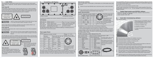
5.Laser SafetyThe <strong>scanCONTROL</strong> <strong>2700</strong> sensors operate with a semiconductor laser having a wavelengthof 658 nm (visible/red). The laser operation is indicated visually by the LED on thesensor.Laser Class 2M<strong>scanCONTROL</strong> <strong>2700</strong> sensors with a maximum laser power up to 10 mW are classifiedin Laser Class 2M (IIM). The following information labels are fitted to the sensor housing(front and rear side). If both information labels are hidden in the installed state, the usermust ensure that additional labels are fitted at the point of installation.IEC 60825-1: 2008-05265WHazard to the eye via laser radiation! Consciously close your eyesor turn away if the laser radiation impinges on the eye.Lasers of Class 2M are not subject to notification and a laser protection officer is notrequired. Mark the laser area recognizable and everlasting.Laser Class 3B<strong>scanCONTROL</strong> <strong>2700</strong> sensors with a maximum laser power up to 20 mW are classified inLaser Class 3B (IIIB).Injury to the eye or the skin via laser radiation! Consciously closeyour eyes or turn away if the laser radiation impinges on the eye orthe skin.Class 3B (IIIB) laser sensors are notifiable and a laser protection officer is required either.During operation the laser area has to be restricted and marked. The following informationlabel should be fitted to the sensor housing (front and rear side):Beam attenuatorLaser radiationAvoid exposure to the beamClass 3B Laser ProductIEC 60825-1: 2008-05P50 mW; =658 nmThe beam attenuator prevents access to alllaser and collateral radiation. The figures showthe sensor with closed and open beam attenuator.The beam attenuator must be open duringmeasurement.iSensors of Laser Class 3B (IIIB)need an external key switch toswitch off the laser, see Chap.“Laser switching”.6.Connections, LED Displays1394/Ethernet24 VDC RS 422LLT<strong>2700</strong>-x, top sidelaser onRS 422state1394/Ethernet24 VDCLLT<strong>2700</strong>-x(001), rear sideThe sensors are available in two versions: Sockets on the top side or on the rear side.LED displaysLED „laser on“LED „state“:Two-color LED(red / green)Green: Laser onGreen: MeasurementGreen flashing: Data transmissionRed flashing: Error codeNote: The “status” LED flashesgreen; long during active datatransmission and short forcontroller accesses.The state LED indicates different error conditions by flashing. If no flashing occurs forseveral seconds, no error has occurred.Power supply (Power)PIN No. Assigment connector „24 VDC“StandardColor PC<strong>2700</strong>Options 002, 003, 004, 005Color PC<strong>2700</strong>(002)1 24 V+ red 24 V+ pink2 n.c. n.c. LH+ grey3 n.c. n.c. Laser off+ yellow4 n.c. n.c. Laser off- green5 n.c. n.c. LH- brown6 24 V GND blackor blue24 V GND whiteRange: 11 V – 30 V(Rated value 24 V) DC;maximum current 500 mA1 62 53 4View on solder pin side,male cable con-nector,counting direction anticlockwiseThe power supply is also possible using the FireWire connection cable, if the power supplyneeded is present in the PC with sufficient current intensity. When both voltages (1394and power) are present, the higher voltage always takes over the supply of the sensor.External laser switchingSeries LLT<strong>2700</strong>-x(002), LLT<strong>2700</strong>-x(003), LLT<strong>2700</strong>-x(004) and LLT<strong>2700</strong>-x(005) sensors offerthis function.iSensors of Laser Class 3B (IIIB) need an external key switch to switch off the laser.Use a serial key switch inside the control circuit to switch off the laser. You will finddetails for the wiring in the instruction manual, Chap. 5.2.4.RS422, SynchronizationPIN No.Assignment connector „RS422“RS422 General 9-pin Sub-D 11 RX1 CH1 22 /RX1 /CH1 35 GND1 53 TX2 CH2 94 /TX2 /CH2 16 GND2 51 62 53 4View on solderpin side, malecable connectorThe RS422 port can be used with either of the following configurations:The PIN numbers referto the <strong>scanCONTROL</strong><strong>2700</strong> unit.<strong>Micro</strong>-<strong>Epsilon</strong> recommendsthe use ofthe interface cableSC<strong>2700</strong>-4.5 RS422 fromthe optional accessories.-- RS422: Loading of programs and transmitting of measurement results.-- Synchronization/Triggering: Synchronization resp. triggering using switching signals.1) Optional RS422 interface cable (SC<strong>2700</strong>-4,5RS422) from <strong>Micro</strong>-<strong>Epsilon</strong>, compatible tothe RS422 to USB converter. All outputs or inputs are designed symmetrically. Internalterminating resistors 120 Ohm.FireWire connection (1394), Standard link to PC8-pin connector, ODU 6-pin connector, FireWire Connector „1394“Pin No. AssignmentPin No. Assignment1 GND_FireWire 2 GND_FireWire2 TPA+ 4 TPB+3 TPA- 3 TPB-4 Screen 2 GND_FireWire5 TPB- 5 TPA-6 TPB+ 6 TPA+7 Screen 2 GND_FireWire8 +24 V_FireWire 1 +24 V_FireWire17328654View on solder pin side563412View on solder pin sideThe PIN numbers refer to the<strong>scanCONTROL</strong> <strong>2700</strong> unit.<strong>Micro</strong>-<strong>Epsilon</strong> recommendsusing the FireWire connectioncable SC<strong>2700</strong>-4.5 FireWirefrom the recommended accessories.The <strong>scanCONTROL</strong> <strong>2700</strong> sensor can also be supplied with operating voltage from the PCon the 1394 connection socket. If its capacity is not sufficient, an appropriate voltage mustbe connected to the 24 VDC socket.Use the recommended FireWire connection cable.A power supply via free cores in the FireWire connection cable is possible if these wiresare connected in the PC (Pin 1 to +8 … 30 V DC, typically 12 V DC; Pin 2 to ground on theFireWire connector).7. System Requirements <strong>scanCONTROL</strong> Software-- Windows XP SP2 (32 bit) / Windows Vista (32 bit) / Windows 7 (32 bit and 64 bit)-- Pentium III ≥ 800 MHz / 512 MB RAM-- Screen resolution: 1024 x 7688.Quick Start: Commissioning, SoftwareInstall the software.Please insert the <strong>scanCONTROL</strong> Demo CDin the CD-ROM device. Follow the dialogthrough the installation process.A. Reading of installation helpB. Installation of softwareMount the sensor according to the installation instructions.Connect the sensor and the PC to the FireWire cable.Connect the sensor to display or monitoring units.Connect the sensor to the power supply.C. Further informations in the online documentationThe connectors for the operating voltage, switching signals and FireWire are fitted withpush-pull locking. Pull apart at the grip to release the connection.iConnect the shield of the power supply cable to the PE protective earth conductorof the main power supply. Close plug-in connections not needed with the suppliedprotective caps for ODU sockets. Switch on the power supply.Only connect the sensor to the peripheral equipment, if it is disconnected fromthe power supply, i.e. only when the operating voltage is switched off. The sensorneeds a warm-up time of typically 20 minutes for high precision measurements.Install the drivers for the measuring system according to the instructions on the suppliedCD-ROM ([CD]:\\Documentation\english\Installation\index.html).
9.Driver Installation for Windows XPFinish the installation of the Configuration Tools software completely. This procedureis described in section 8. Connect the sensor to the PC using the 1394 FireWirecable. Switch on the power supply.If the installation doesn’t start automatically, search for <strong>scanCONTROL</strong> in the device manager(Start > Control Panel > System > Device Manager). <strong>scanCONTROL</strong> is classified ascamera device and is either located under “Imaging Devices” or “Other Devices”. Rightclickthe camera device and choose “Update Driver”.Assembly Instructions<strong>scanCONTROL</strong> <strong>2700</strong>The ”Hardware Update Wizard” will appear.Mark “No, not this time” and click on “Next”.Click on ”Next” to confirm this dialog.Now the operating system installs the driver for <strong>scanCONTROL</strong>. The ”Hardware installation”dialog will appear.Click on ”Continue anyway” to confirm this dialog.Click on “Finish” to end the driver installation.If you want to install the driver at a later date or in case of an incorrect installation of thedriver, you have to install the driver manually.10.First ProfileNow start the <strong>scanCONTROL</strong> Configuration Tools software. Click on „Display Profiles“in the main window.If the software shows the error message “No <strong>scanCONTROL</strong> found” in the status line,please check the installed driver in the device manager (Start > Control Panel > System> Device Manager).On the left side you can adjust the settings for your measurement task, the right sideshows the profile data and information about the measurement.11.How to Access Profile DataProfile data of <strong>scanCONTROL</strong> can be accessed via:-- DCAM standard v.1.30 for digital cameras via IEEE 1394 FireWire interface-- SDK for fast application integration (C, C++ and others)For details refer to the enclosed online manuals.12.Please refer toFurther Information-- the enclosed online manual-- the section „Status and Error Messages“ and „Notes“ in the <strong>scanCONTROL</strong> ConfigurationTools manual.You will find details to the separate programs in the respective instruction manuals or inthe instruction manual of this sensor, Chap. 6.2. You will find the instruction manuals onlineor on the provided CD.*X9771182-A06*www.micro-epsilon.comMICRO-EPSILON Messtechnik GmbH & Co. KGKönigbacher Str. 1594496 Ortenburg, Germany, Tel. +49 (0) 85 42/1 68-0X9771182-A061082MSC1.WarningsConnect the power supply and the display-/output device in accordance with the safetyregulations for electrical equipment. The power supply may not exceed the specifiedlimits.>> Danger of injury, damage or destruction of the sensorAvoid shock and vibration to the sensor. Avoid continuous exposure to dust and sprayon the sensor. Avoid exposure to aggressive materials (e. g. washing agent, penetratingliquids or similar) on the sensor.>> Damage to or destruction of the sensorRead the detailed instruction manual before operation of the sensor. You will find thisonline or on the provided CD.2.Notes on CE IdentificationThe following applies to the <strong>scanCONTROL</strong> <strong>2700</strong>: EU Regulation 2004/108/EGThe sensor fulfills the specifications according to the following standards:-- DIN EN 55011/ 11.2007 / Industrial scientific and medical (ISM) equipment / Electromagneticdisturbance characteristics-- DIN EN 61 000-6-2/ 03.2006 / Electromagnetic Compatibility (EMC) / Immunity to interference/ industrial area-- DIN EN 61326/ 10.2006 / Electrical equipmentThe sensor fulfills the specifications of the EMC requirements, if the instructions in themanual are followed.3. Proper Environment-- Protection class: IP 65-- Operating temperature: 0 to +50 °C (+32 to +122 °F), by free circulation of air-- Storage temperature: -20 to +70 °C ( -4 to +158 °F)-- Humidity:5 - 95 % (non condensing)-- Vibration:DIN EN 60068-2-6 (sine shaped)-- Mechanical shock: DIN EN 60068-2-294. Standard Equipment <strong>scanCONTROL</strong> <strong>2700</strong>-- 1 Sensor LLT<strong>2700</strong> with integrated controller-- 1 Power supply cable PC<strong>2700</strong>-4.5, length 4.5 m; ODU round connector and free cableends-- 1 <strong>scanCONTROL</strong> Demo-CD with drivers, programs and documentation-- 1 Sensor inspection log / assembly instructions-- 1 Bag of accessories with one ODU male connector 6-pin (RS422), S31BQC-P06M-FG0-6000, and two protective caps for ODU female connector (6- or 8-pin)