Installation instructions and short operating ... - Micro-Epsilon
Installation instructions and short operating ... - Micro-Epsilon
Installation instructions and short operating ... - Micro-Epsilon
- No tags were found...

You also want an ePaper? Increase the reach of your titles
YUMPU automatically turns print PDFs into web optimized ePapers that Google loves.
ASCOspeed ASP5500Assembly InstructionsMICRO-EPSILON Optronic GmbHLessingstrasse 1401465 Dresden-Langebrueck,GermanyTelephone: +49 35201 / 729 - 0Telefax: +49 35201 / 729 - 90www.micro-epsilon.de optronic@micro-epsilon.de1. Safety <strong>instructions</strong>1.1. GeneralOscillation-free mounting plate with four M6 fasteningscrew threads.Ensure heat dissipation to the support.Ensure sufficient scavenging air in rolling mills.Keep a mounting distance to target of 300mm.M6x40 hexagon socket (Allen) bolts (or longer, notincluded in the scope of delivery).5. Alignment• Mount at right angles to the surface to be measured.• Arrow on jack panel movement direction set atthe factory.IF2SERVICEIF1IF3POWERNotes:• Arrow on jack panel movement directionof the object beingmeasured (set at thefactory).Direction can bechanged byparameterisation!• IF2 <strong>and</strong> IF3 onlyavailable in the versionwith interface expansionmodule.• See also <strong>operating</strong><strong>instructions</strong> forcomplete pinassignment10. Operation with a PC10.1. Setting up• Connect the ASCOspeed 5500 to the serial port (COM;RS232) of a PC using the C5500-5/RS232 servicecable.• Start a terminal program (e.g.: "Hyperterminal" from<strong>Micro</strong>soft Windows "Accessories Communications".• Basic settings: 9600 baud, no parity <strong>and</strong> protocolXON/XOFF (9600, 8N1, XON/XOFF).Set the display in the terminal program to "String".10.2. Help• The READ comm<strong>and</strong> (or Read or reAD or read)returns all the parameters set as answer.Refer to the manual. Operation only within specification.Supply voltage 20 V … 28 V DC (direct current)Persons must not be endangered or equipment damageddue to malfunction or total failure of the sensor.1.2. Operational environmentProtection rating: IP65 (only applicable to water),IP67 (in stainless steel housing with oil resistantgaskets)Operating temperature: 0 ... 50 °C (withoutexternal cooling)Storage temperature: -20 ... +70 °CEMC st<strong>and</strong>ards: DIN EN 61326-1:2006• Interference emission EN 61 000-6-3 / DIN EN55011• Interference resistance: EN 61 000-6-2 / DIN EN613261.3. CautionGlare: Do not stare directly into the LED light or its directreflection at the object being measuredProtective case: Be careful when opening. The cover isheavy <strong>and</strong> not locked!2. St<strong>and</strong>ard equipment• ASCOspeed 5500 with accompanying CD <strong>and</strong>assembly <strong>instructions</strong>,• PC5500-5 power cable, length 5 m,• C5500-5 service cable, Sub-D female connector (COMinterface).3. Optional accessories• SC5500-x/IF1 interface cable (or IF2 or IF3), can beused in a cable carrier system, with free cable ends,length x = 5 m or 15 m.• PS2010 power pack, 24 VDC / 2.5 A• SC5500-10/MS connection cable for master-slaveoperation, length 10 m.4. <strong>Installation</strong> <strong>and</strong> mountingUnobstructed view of the target.Smooth, stable running of the target, installation asclose as possible to guiding elements, rollers, etc.Do not measure on curved surfaces!MovementCorrect installation Tilting <strong>and</strong> rotating6. <strong>Installation</strong> <strong>instructions</strong>• Only connect devices when system is switched off.• In addition, connect the service cable (included) toallow access to the device at any time.• The smallest bending radius for the cablesrecommended is 60 mm.7. DisplayLEDs on the device side:"signal"• Green: Signal OK• Red: No signal• Yellow: Device isinitialising"busy" yellow comm<strong>and</strong> processing / calibration / offlinemeasurement"error" redMovementflashes in event of "fatal error" or is brieflylit in case of "critical error"Note: Materials moved <strong>and</strong> "signal" LED lights up brieflygreen valid measured values.8. ConnectionsPower:+24 V in: pin 1 (white)0V in: pin 2 (brown)Colours for PC 5500-5 power cableMovementl (on rear of device)Interface socket IF1,(extract)SignalPin9. Commissioning16-poleJackpaneColouronsocket1. Connect the ASCOspeed via the PC5500-5 powercable.2. Switch on the power supply for the ASCOspeed5500. A bright red spot of light will appear on the target.3. Display: LEDs on the device side are lit up asdescribed in Chapter 7 "Display". The smallest bendingradius for the cables recommended is 60 mm. Note:Move target "signal" LED lights up briefly green(valid measured values).4. Activation of the pulse outputs, see 10.3.5. Connect the encoder display device with its own<strong>operating</strong> voltage at the OUT1 A <strong>and</strong> B pulse output(interface socket IF1).Note: For the HTL level at OUT1, connect anadditional <strong>and</strong> suitable auxiliary voltage atPOWEREXT (H) <strong>and</strong> GNDEXT (G) from IF1.See <strong>operating</strong> <strong>instructions</strong> for circuit <strong>and</strong> setting options.FGEHDOPCINRKBMLColour in thecableSC5500-x/IF1OUT1A+ A wht whtOUT1A- B br brOUT1B+ C ye yeOUT1B- D gn gnGNDEXT1 G blu bluPOWEREXT1 H red redGND-OUT1 I bla blaNot assigned K pur purDIR IN+ L pnk-gr gr-pnkDIR IN- M red-blu red-bluTRIG IN+ N wht-gn wht-gnTRIG IN- O br-gn br-gnA• Using the "Help" comm<strong>and</strong> or "?", all the validcomm<strong>and</strong>s will be listed without any commentary - withthe "Help comm<strong>and</strong>"only information on the selectedComm<strong>and</strong> will be listed.1.10.3. Activation of the pulse outputPulse interface OUT1 (on IF1): 5V TTL level2 . Selection of the scaling factor: INCFACTOR 1 1 (e.g.for 1 pulse / mm on the OUT 1 channel)3. Activation of the OUT1 pulse output by means of theRS232 service interface (baud rate, parameter ...):Activation comm<strong>and</strong>: INCOn 1 14. Save the activation using the *store comm<strong>and</strong><strong>and</strong> the password: microSee the <strong>operating</strong> instruction s for details ofcommunication comm<strong>and</strong>s.11. Additions11.1. Factory settingsother• The ASCOspeed 5500 is completely functional with itsfactory settings.• The internal brightness regulator is switched on <strong>and</strong>takes over the automatic adaptation to the target.• All outputs inactive, communication only possibleusing the S1 service port.11.2. CD-ROM <strong>and</strong> Internet• Sample files for typical applications are provided onthe enclosed CD-ROM, transmission to theASCOspeed by means of a terminal program (see10.1).• Other documents of the sensor concerned can befound at "Download" at http://www.micro-epsilon.de/ready to be downloaded from MICRO-EPSILON.Subject to alterations.Assembly <strong>instructions</strong> ASCO_en_03.doc, Status as of: 05.11.2010 10:45:00
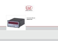
Dimensional drawing of the ASP5500 (dimensions in mm, not to scale)Weight approx. 5.6 kg11.3. Stainless steel housingThe stainless steel housing is designed for mechanical protection, but not as a sole means of heat dissipation in a hotenvironment.Please note• Ensure sufficient scavenging air in rolling mills.• Be careful opening it when it is in mounted condition. The cover of the protective case is heavy <strong>and</strong> not locked!• Do not fit the tube if it is in a twisted condition! Pay attention to the dimensional drawing• Keep a distance of 265 mm from the protective case to the target (plate)Dimensional drawing of the ASP5500 (dimensions in mm, not to scale), weight: approx. 33 kg70115126530050050506020547570160115Assembly <strong>instructions</strong> ASCO_en_03.doc, Status as of: 05.11.2010 10:45:00