Manual induSENSOR Serie EDS - Micro-Epsilon
Manual induSENSOR Serie EDS - Micro-Epsilon
Manual induSENSOR Serie EDS - Micro-Epsilon

Create successful ePaper yourself
Turn your PDF publications into a flip-book with our unique Google optimized e-Paper software.
Instruction <strong>Manual</strong><strong>induSENSOR</strong>, <strong>EDS</strong><strong>EDS</strong>-75-S<strong>EDS</strong>-100-S/F<strong>EDS</strong>-160-S/F<strong>EDS</strong>-200-S/F<strong>EDS</strong>-220-Z<strong>EDS</strong>-250-S/F<strong>EDS</strong>-260-Z<strong>EDS</strong>-300-S/F/Z<strong>EDS</strong>-370-Z<strong>EDS</strong>-400-S/F/Z<strong>EDS</strong>-500-S<strong>EDS</strong>-630-S/F
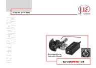
Long-Stroke sensors, <strong>Serie</strong>s <strong>EDS</strong>MICRO-EPSILONMESSTECHNIKGmbH & Co. KGKönigbacher Strasse 1594496 Ortenburg / GermanyTel. 08542/168-0Fax 08542/168-90e-mail info@micro-epsilon.dewww.micro-epsilon.comCertified acc. to DIN EN ISO 9001: 2008
Contents1. Safety......................................................................................................................................... 51.1 Symbols Used.................................................................................................................................................. 51.2 Warnings........................................................................................................................................................... 51.3 Notes on CE Identification................................................................................................................................ 61.4 Proper Use........................................................................................................................................................ 61.5 Proper Environment.......................................................................................................................................... 72. Functional Principle, Technical Data........................................................................................ 82.1 Measuring Principle.......................................................................................................................................... 82.2 Structure........................................................................................................................................................... 92.3 Technical Data................................................................................................................................................ 103. Delivery.................................................................................................................................... 123.1 Unpacking....................................................................................................................................................... 123.2 Storage........................................................................................................................................................... 124. Installation and Assembly....................................................................................................... 134.1 Precautionary Measures................................................................................................................................. 134.2 Measuring Tube Guide and Fastening........................................................................................................... 134.3 Sensor Mounting............................................................................................................................................ 154.3.1 Model <strong>EDS</strong>- ... -S........................................................................................................................... 154.3.2 Model <strong>EDS</strong>- ... -F........................................................................................................................... 224.3.3 Model <strong>EDS</strong>- ... -Z........................................................................................................................... 244.4 Power Supply and Display/Output Device..................................................................................................... 274.4.1 Model <strong>EDS</strong>- ... -S........................................................................................................................... 274.4.2 Model <strong>EDS</strong>- ... -F........................................................................................................................... 294.4.3 Model <strong>EDS</strong>-...-Z............................................................................................................................. 304.4.4 Load Resistor, Maximum Operating Temperature........................................................................ 32<strong>induSENSOR</strong>, <strong>EDS</strong>
5. Operation................................................................................................................................. 336. Operation and Maintenance................................................................................................... 337. Warranty................................................................................................................................... 348. Decommissioning, Disposal................................................................................................... 349. Appendix.................................................................................................................................. 35<strong>induSENSOR</strong>, <strong>EDS</strong>
1. SafetyThe handling of the system assumes knowledge of the instruction manual.1.1 Symbols UsedThe following symbols are used in this instruction manual:Indicates a hazardous situation which, if not avoided, may result in minor or moderateinjury.Indicates a situation which, if not avoided, may lead to property damage.i1.2 WarningsIndicates a user action.Indicates a user tip.Connect the power supply according to the safety regulations for electrical operating equipment.> > Danger of injury> > Damage to or destruction of the sensorThe supply voltage must not exceed specifiedlimits.> > Damage to or destruction of the sensorAvoid banging and knocking the sensor.> > Damage to or destruction of the sensorSensorhousingSensor rodAlu tubeAvoid bending the sensor rod or the alu tube.> > Damage to or destruction of the sensorSensorhousingDo not transport the sensor on the sensor rod.> > Damage to or destruction of the sensor<strong>induSENSOR</strong>, <strong>EDS</strong>Page 5
1.3 Notes on CE IdentificationThe following applies to <strong>EDS</strong> eddy current long stroke displacement sensors:EMC regulation 2004/108/ECProducts which carry the CE mark satisfy the requirements of the EMC regulation 2004/108/EC‘Electromagnetic Compatibility’ and the European standards (EN) listed therein. The EC declaration of conformityis kept available according to EC regulation, article 10 by the authorities responsible atMICRO-EPSILON MESSTECHNIK GmbH & Co. KGKoenigbacher Straße 15D94496 OrtenburgThe eddy current long stroke displacement sensors are designed for use in industry and satisfy there requirementsof the standards:--DIN EN 61326-1: 2006-10--DIN 61326-2-3: 2007-05The sensors satisfy the requirements if they comply with the regulations described in the instruction manualfor installation and operation.1.4 Proper Use--The sensors are used for• displacement measurement in presses, punches, rolling mills, et cetera• position determination of piston in hydraulic and pneumatic cylinders--The sensors may only be operated within the limits specified in the technical data, see Chap. 2.3.--Use it in such a way that with malfunctions or total failure of the sensor, persons are not endangered andmachines are not damaged.--Take additional precautions for safety and damage prevention for safety-related applications.<strong>induSENSOR</strong>, <strong>EDS</strong>Page 6
1.5 Proper Environment--Protection class for sensor• Sensor rod IP 69K• Electronics: IP 67 1--Operating temperature: -40 °C to +85 °C (-40 to +185 °F), R L= 500 Ohm--Storage temperature: -40 °C to +100 °C (-40 to +212 °F)--Humidity: 5 - 95 % (no condensation)--Ambient pressure: 450*10 5 Pa (1 Pa = 1 N/m 2 ) max. 2--EMC: According to: DIN EN 61326-1: 2006-10DIN 61326-2-3: 2007-051) Models with male plug connection only with gasketed female plug2) Confined on sensor rod<strong>induSENSOR</strong>, <strong>EDS</strong>Page 7
2. Functional Principle, Technical Data2.1 Measuring PrincipleThe eddy current long stroke displacement sensors transform a linear motion (for example piston position inhydraulic cylinders) into a linear, electrical signal. An aluminium tube, moving concentrically around a sensorrod, is used as target. Energy is transferred from the coil by inducing of eddy currents in the aluminium tubeand it is detuned as a result. The integrated, miniaturized electronics convert the tube position into a linear,electrical output signal. The eddy current measuring principle works without contact between moving partsand is therefore free of wear.Output signal (mA)201240 1/2 Measuring range 1/1SensorhousingSensor rodAlu tubeFig. 1 Measuring Principle of an eddy current long stroke displacement sensor, alu tube at the start of themeasuring range<strong>induSENSOR</strong>, <strong>EDS</strong>Page 8
2.2 StructureA coil is mounted inside the sealed rod, protected against environmental influences. The micro-electronics isintegrated in the sensor housing. A pressure-proof, stainless steel housing is available as an option. The sensorsare used for measuring lengths from 100 to 630 mm.Electrical connection:--Connector 4-pins, type Amphenol C164P compact (Model <strong>EDS</strong>-...-S...) 1--Connector 7-pins, type Binder 712 (Model <strong>EDS</strong>-...- S ...7...)--Connector 5-pins, CA02COM-E14S with bayonet connection (Model <strong>EDS</strong>-...-F...)--Wire, axial (model <strong>EDS</strong>-...-Z...)1) Previous model no longer available<strong>induSENSOR</strong>, <strong>EDS</strong>Page 9
2.3 Technical DataModel<strong>EDS</strong>-75<strong>EDS</strong>-100<strong>EDS</strong>-160Connections S S, F S, F S, F Z S, F Z S, F, Z Z S, F, Z S S, FMeasuring range mm 75 100 160 200 220 250 260 300 370 400 500 630<strong>EDS</strong>-200Linearity ±0.3 % FSO mm 0.23 0.3 0.48 0.6 0.66 0.75 0.78 0.9 1.1 1.2 1.5 1.89Resolution 0.05 % FSO mm 0.038 0.05 0.08 0.1 0.11 0.125 0.13 0,15 0.18 0.2 0.25 0.315Repeatability<strong>EDS</strong>-220<strong>EDS</strong>-250<strong>EDS</strong>-2600.05 % FSOTemperature range -40 °C ... +85 °CTemperature stability ±200 ppm / °C<strong>EDS</strong>-300Frequency response -3 dB 150 Hz, optional up to 300 HzOutput signalOutput loadPower supplyCurrent consumptionConnectorModel SModel FModel Z4 - 20 mA≤ 500 Ohm18 - 30 VDCmax. 40 mA<strong>EDS</strong>-370<strong>EDS</strong>-4007-pin connector (sensor cable as an option), options radial or axial output5-pin radial bayonet-connector with mating plugWire axialPressure resistance 450*10 5 Pa max. (Sensor rod, flange) 1Protection class Sensor rod: IP 69K, elektronics: IP 67 2ElektromagneticDIN EN 61326-1: 2006-10compatibility (EMC) 3 DIN 61326-2-3: 2007-05Shock 4 IEC 68-2-29IEC 68-2-27Vibration EC 68-2-640 g, 3000 shocks per axis100 g radial, 300 g axial5 Hz ... 44 Hz ±2.5 mm44 Hz ... 500 Hz ±23 g<strong>EDS</strong>-500<strong>EDS</strong>-630<strong>induSENSOR</strong>, <strong>EDS</strong>Page 10
Model<strong>EDS</strong>-75<strong>EDS</strong>-100<strong>EDS</strong>-160Connections S S, F S, F S, F Z S, F Z S, F, Z Z S, F, Z S S, F<strong>EDS</strong>-200<strong>EDS</strong>-220<strong>EDS</strong>-250<strong>EDS</strong>-260Sensor material V4A-Steel 1.4571Tube materialSensor weight<strong>EDS</strong>-...-SAlMgSi, enodized<strong>EDS</strong>-300<strong>EDS</strong>-370<strong>EDS</strong>-400<strong>EDS</strong>-500<strong>EDS</strong>-...-Z --- --- --- --- 340 --- 370 370 570 570 --- ---gS 20 30 40 40 --- 50 --- 60 --- 90 115 140<strong>EDS</strong>-630150 170 160 220 --- 250 --- 280 --- 470 560 650<strong>EDS</strong>-...-F --- 1260 1270 1300 --- 1320 --- 1350 --- 1560 --- 1750Alu tubeFSO = Full Scale Output1) For all models confined on sensor rod2) With gasketed female plug.3) Model Z only when integrated.4) Half sinusoid 6 ms.F --- 40 40 40 --- 50 --- 60 --- 140 --- 210Z --- ---- --- --- 46 --- 54 60 92 90 --- ---<strong>induSENSOR</strong>, <strong>EDS</strong>Page 11
3. Delivery3.1 UnpackingDo not take and hold the sensor at the sensor rod.Check for completeness and shipping damage immediately after unpacking.SensorhousingThe delivery of an eddy current long stroke displacement sensor includes:1 Eddy current long stroke displacement sensor 1 O-ring (mounted on sensor) 11 Measuring tube 1 Test report1 Instruction manualIn case of damage or missing parts, please contact the manufacturer or supplier.3.2 Storage--Storage temperature: -40 °C up to +100 °C (-40 to +212 °F)--Humidity: 5 - 95 % (no condensation)--Atmospheric pressure1) For sensor models S and F only<strong>induSENSOR</strong>, <strong>EDS</strong>Page 12
4. Installation and Assembly4.1 Precautionary MeasuresThe measuring tube must not contact the sensor rod during operation.> > Damage to or destruction of the sensor through abrasion is possible.Do not deform or shorten the measuring tube.> > Loss of specified technical data.Do not crush the O-ring or damage through sharp-edged items.> > Loss of functionality4.2 Measuring Tube Guide and FasteningMount the measuring tube in the piston bore hold.The dimensions for the measuring tube are shown, see Fig. 8 et seq. When the piston is moved in the measuringtube must not touch the sensor shaft. Observe the measuring tube position at the zero point(= 4 mA output), see Fig. 2 et seq. A slightly eccentric mounting of the measuring tube has no negative influenceon the sensor signal.Mount the measuring tube in the piston by means of pressing or glueing.Spot clamping is not permissible.iThe specified technical data are valid only if the measuring tube is used supplied byMICRO-EPSILON!<strong>induSENSOR</strong>, <strong>EDS</strong>Page 13
aaFig. 2 Zero point of the measuring tube, <strong>EDS</strong>- ... -S Fig. 3 Zero point of the measuring tube, <strong>EDS</strong>- ... -FMeasuring range Dimension a75 15 (0.59)100 20 (0.79)160 20 (0.79)200 20 (0.79)220 20 (0.79)a250 20 (0.79)260 20 (0.79)Fig. 4 Zero point of the measuring tube, <strong>EDS</strong>- ... -Z 300 20 (0.79)370 25 (0.98)Dimensions in mm, not to scale 400 25 (0.98)500 25 (0.98)630 25 (0.98)<strong>induSENSOR</strong>, <strong>EDS</strong>Page 14
4.3 Sensor Mounting4.3.1 Model <strong>EDS</strong>- ... -SMount the sensor in the cylinder with a mounting ring (Appendix), see Fig. 12 and six cylinder head bolts(M5x10).Sealing is effected at the sensor shaft by means of an O-ring supplied.Displacementsensor O-ring Sensor rodCylinderPiston21HBM5x10Mounting ringSensor shaftAlu tubeFig. 5 Sensor mounting in a hydraulic cylinder, model <strong>EDS</strong>- ... -SSealingO-Ring: 18.5x1.5Material: VitonDiameter of the borehole: 21H8 dia.Borehole surface:R a= 0.8R max= 3.2Dimension21H8Fit toleranceµm+330<strong>induSENSOR</strong>, <strong>EDS</strong>Page 15
ø34 (1.4 dia.)15(.6)ø31(1.2 dia.)Use a connection piece for mounting,see Fig. 6. The bushing mustbe congruent with the connector formodels with radial connector.Bushing forconnector40 (1.6)Fig. 6 Mounting of an <strong>induSENSOR</strong>, model <strong>EDS</strong>- ... -SUse an extractor for dismounting,see Fig. 7.Dimensions of the flange groove:1.5 x 1.5 mm(.06 x .06 “,depth x width).GrooveFig. 7 Dismounting of an <strong>induSENSOR</strong>, model <strong>EDS</strong>- ... -SDimensions in mm, not to scale<strong>induSENSOR</strong>, <strong>EDS</strong>Page 16
Dimensional drawing, model <strong>EDS</strong>- ... -Smin 30(1.18)ABø30 (1.18 dia.)32.5 (1.28)4 +0.1(.16 +0.1 )ø34 -0.1(1.34 -0.004 dia.)ø21f7 (.83 dia.)ø10 (.39 dia.)d8 -0.1(.32 -0.004 )lAlu tube ISensor rod LL1.5 (.06)Fig. 8 <strong>induSENSOR</strong> with axial connector, model <strong>EDS</strong>- ... -SA7 - I,measuring range: 75 (2.95) / 100 (3.94) / 160 (6.29) / 200 (7.87) /250 ( 9.84) / 300 (11.81)Dimension21f7Fit toleranceµm-20-41Dimensions in mm (inches), not to scale1) Previous model no longer available.<strong>EDS</strong>-xxx-S-Sx-l 1 31 (1.2) 16 (.63)<strong>EDS</strong>-xxx-S-Sx7-l 51 (2.0) 47 (1.85)ABMeasuringrange100(3.93)160( 6.29)200(7.87)250(9.84)300(11.81)Sensor rod L140(5.51)200(7.87)240(9.45)290(11.42)340(13.39)Alu tube I Alu tube d140(5.51)200(7.87)240(9.45)290(11.42)340(13.39)16(.63)16(.63)16(.63)16(.63)16(.63)<strong>induSENSOR</strong>, <strong>EDS</strong>Page 17
A13(0.51)Fig. 9 <strong>induSENSOR</strong> with radial connector, model <strong>EDS</strong>- ... -SR7 - I, measuring range: 75 (2.95) / 100 (3.94) /160 (6.29) / 200 (7.87) / 250 (9.84) / 300 (11.81)A<strong>EDS</strong>-xxx-S-Sx-I 1 31(1.2)<strong>EDS</strong>-xxx-S-Sx7-I51(2.0)Dimensions in mm, not to scale1) Previous version no longer available.<strong>induSENSOR</strong>, <strong>EDS</strong>Page 18
min 30(1.18) ABø30 (1.18 dia.)32.5 (1.28)4 +0.1(.16 +0.1 )ø12(.47 dia.)ø21f7(.83 dia.)16 -0,1(.63 -0.004 )dlAlu tube ISensor rod LL1.5 (.06)Fig. 10 <strong>induSENSOR</strong> with axial connector, model <strong>EDS</strong>- ... -SA7 - I, measuring range: 400 (15.74) / 500 (19.69) /630 (24.80), dimensions in mm (inches), not to scaleDimension ToleranceµmA B21f7-20-41<strong>EDS</strong>-xxx-S-Sx-l 1 31(2.19)<strong>EDS</strong>-xxx-S-Sx7-l51(2.1)16(.63)47(1.85)1) Previous version no longeravailable.Measuring Sensor rodAlu tuberangeL I d400 (15.74) 450 (17.72) 450 (17.72) 18 (.71)500 (19.69) 550 (21.65) 550 (21.65) 18 (.71)630 (24.80) 680 (26.77) 680 (26.77) 18 (.71)<strong>induSENSOR</strong>, <strong>EDS</strong>Page 19
A13(0.51)Fig. 11 <strong>induSENSOR</strong> with radial connector, model <strong>EDS</strong>- ... -SR7 - I, measuring range: 400 (15.74) / 500 (19.69)/ 630 (24.80)A<strong>EDS</strong>-xxx-S-Sx-I 1 31 (1.2)<strong>EDS</strong>-xxx-S-Sx7-I 51 (2.0)Dimensions in mm (inches), not to scale1) Previous version no longer available.<strong>induSENSOR</strong>, <strong>EDS</strong>Page 20
ø80.0 (ø3.15)12.0 (.47)abcda ø6.2 (ø.24)b ø34.0 +0.05 (ø1.34 +0.002 )c ø31.0 +0.1 (ø1.22 +0.004 )d ø16.0 (ø.63)3.95 -0.05 (.16 -0.002 )1.0 (.04)30.0 °ø55.0 (ø2.17)8.0(.32)Fig. 12 Mounting ring, model <strong>EDS</strong>- ... -S, dimensions in mm (inches), not to scale<strong>induSENSOR</strong>, <strong>EDS</strong>Page 21
4.3.2 Model <strong>EDS</strong>- ... -FThe sensor is mounted in the cylinder by means of cylinder head bolts (6 x M8). The sealing is effected at thesensor shaft by means of an O-ring supplied.Cylinder headbolt M8Sensor rod Cylinder Piston42F7DisplacementsensorO-ringSensor shaftAlu tubeFig. 13 Sensor mounting in a hydraulic cylinder, model <strong>EDS</strong>- ... -FSealingO-Ring: 38x2.0Material: PURDiameter of the borehole: 42F7 dia.Borehole surface:R a= 0.8R max= 3.2Dimensions Fit toleranceµm42F7 +50+25<strong>induSENSOR</strong>, <strong>EDS</strong>Page 22
Dimensional drawing, model <strong>EDS</strong>- ... -Fø29 (1.14 dia)18.0 (.71)76.0 (2.99)ø42.0 -0.05 (2 99 -0.002 dia.)DdSensor rod LAlu tube I59 (2.32 )O-ring groove35.0(1.38)20.0(0.79)MeasuringrangeSensor rodAlu tubeL D I d100 (3.93) 140 (5.51) 10 (0.39) 140 (5.51) 16 (0.63)160 (6.29) 200 (7.87) 10 (0.39) 200 (7.78) 16 (0.63)200 (7.87) 240 (9.45) 10 (0.39) 240 (9.45) 16 (0.63)250 (9.84) 290 (11.42) 10 (0.39) 290 (11.42) 16 (0.63)300 (11.81) 340 (13.39) 10 (0.39) 340 (13.39) 16 (0.63)400 (15.74) 450 (17.72) 12 (0.47) 460 (18.11) 26 (1.02)630 ( 24.80) 680 (26.77) 12 (0.47) 690 (27.17) 26 (1.02)ø63.0 (2.48 dia.)ø80.0 (3.15 dia.)Fig. 14 <strong>induSENSOR</strong> with radial connector,model <strong>EDS</strong>- ... -F, dimensions in mm (inches),not to scale<strong>induSENSOR</strong>, <strong>EDS</strong>Page 23
4.3.3 Model <strong>EDS</strong>- ... -ZThe sensor is fixed in the cylinder with a grub screw and clamped from the back panel. Sealing is effected atthe sensor shaft by means of an O-ring.Feed the connecting wires in able duct outwards and connect them with the mounting plug.Sealing (not included inthe delivery)O-Ring:44.12x2.62material: VitonBack panelGrub screw Sensor rod Alu tube Piston>18 15Diameter of the borehole:48H8 dia.,borehole surface:R a= 0.8R max= 3.2> 2548H8<strong>induSENSOR</strong>, <strong>EDS</strong>O- ringAdapterM12x1 Mounting plug, 4-pin.Fig. 15 Sensor mounting in a hydraulic cylinder, model <strong>EDS</strong>- ... -ZDimension48H8Fit toleranceµm+390Alu tube must beflush with the pistonPage 24
Dimensional drawing, model <strong>EDS</strong>- ... -ZAlu tube I33 (1.3)21(0.82)12(0.47) 1 x 45 °dø48f7 (1.89 dia.)ø44 -0.3 (1.73 -0.12 dia.)ø44 -0.1 (1.73 -0.004 dia.)M24x1.5Sensor rod LDFig. 16 <strong>induSENSOR</strong> with axial wires,model <strong>EDS</strong>- ... -Z, dimensions in mm (inches),not to scaleDimension Fit toleranceµm48f7-25-50Measuring Sensor rodAlu tuberangeL D I d220 (8.66) 252 (9.92) 10 (.39) 250 (9.84 16 (.63)260 (10.23) 292 (11.50) 10 (.39) 290 (11.42) 16 (.63)300 (11.81) 341 (13.43) 10 (.39) 340 (13.39) 16 (.63)370 (14.57) 457 (17.99) 12 (.47) 450 (17.72) 18 (.71)400 (15.74) 457 (17.99) 12 (.47) 450 (17.72) 18 (.71)<strong>induSENSOR</strong>, <strong>EDS</strong>Page 25
Use an extractor pipe for dismounting, see Fig. 17.Female thread in the extractor pipe: M24 x 1.5Proceeding:1. Unplug the adapter.2. Release the grub screw3. Screw on the extractor pipe on the sensor shaft and pull out the sensor from the cylinder.2 3Extractor pipe1Fig. 17 Dismounting of the <strong>induSENSOR</strong>, model <strong>EDS</strong>- ... -Z<strong>induSENSOR</strong>, <strong>EDS</strong>Page 26
4.4 Power Supply and Display/Output Device4.4.1 Model <strong>EDS</strong>- ... -SThe power supply and the signal output are effected through 7-pin connector on the sensor’s electronichousing. The pin assignment is shown, see Fig. 19.View on solder pinside, female cableconnectorPin Assignment ColorC703-51 Power supply + (18 ... 30 VDC) white2 0 V Ground brown3 I OUT4 ... 20 mA 1 green4 Signal ground yellow5 SCL (Sensor calibration) grey6 SCL (Sensor calibration) pink7 n.c. bluePin 2 is connected withpin 4 on the electronicsboard. The screen of thesensor cable is connectedwith the connector housing.Connect the screen ofthe sensor cable with theprotective earth conductoron power side.Fig. 18 Binder connectorType 702Fig. 19 Connection pin assignment, 7-poleThe sensor cable C703-5 and C704-5, length 5 m, are available as an accessory.1) Output voltage of 1 up to 5 V with the C703-5/U supply and output cable.<strong>induSENSOR</strong>, <strong>EDS</strong>Page 27
<strong>EDS</strong>-...-S118...30 VDC+R Lcan be inserted as an option for adaptationof the power loss to high ambienttemperatures, see Chap. 4.4.4.23R LU B_+I OUTA4_Fig. 20 Signal monitoring with amperemeter<strong>EDS</strong>-...-S123I S18...30 VDCU+B_+If the signal is monitored with a voltmeterthe load resistor R Lis sized to give the desiredoutput voltage U OUT.Formula: U OUT= R L* I SignalR LU OUTV4_Fig. 21 Signal monitoring with load resistorand voltmeter<strong>induSENSOR</strong>, <strong>EDS</strong>Page 28
ConnectorType CA02COM-G14SThe C705-5 sensorcable is available as anaccessory.4.4.2 Model <strong>EDS</strong>- ... -FPower supply and signal output are effected through the 5-contact connector on the sensor’s electronichousing. The pin assignment is shown, see Fig. 22.Pin Assignment A 5-pin cable socket for the user-side assemblyof your own connecting cable isA Power supply + (18 ... 30 VDC)part of the delivery scope.BGroundC4 ... 20 mAD Housing Fig. 22 Table connection pin assignment,E ---bayonet connection, view of solder pinside female cable connector<strong>EDS</strong>-...-FAEB18...30 VDC+U B_R Lcan be inserted as an option for adaptationof the power loss to high ambienttemperatures, see Chap. 4.4.4.CDR LIOUTA+_Fig. 23 Signal monitoring with amperemeter<strong>induSENSOR</strong>, <strong>EDS</strong>Page 29
<strong>EDS</strong>-...-FAEB18...30 VDC+U B_If the signal is monitored with a voltmeterthe load resistor R Lis dimensioned in accordancewith the desired output voltageU OUT.Formula: U OUT= R L* I SignalCDI SR LU OUTFig. 24 Signal monitoring with load resistorand voltmeter4.4.3 Model <strong>EDS</strong>-...-ZPower supply and signal output are effected through the 4-contact connector on the hydraulic cylinder. Thepin assignment is shown, see Fig. 25.Pin Assignment Color A 4-pin cable socket for the1 Signal ground brown user-side assembly of yourown connecting cable is2 Power supply + (18 ... 30 VDC) whitepart of the delivery scope.3 Signal (4 ... 20 mA) blue4 Supply ground blackFig. 25 Connection pinassignment, view of solderpin side female cable connectorV+<strong>induSENSOR</strong>, <strong>EDS</strong>Page 30
<strong>EDS</strong>-...-ZR Lcan be inserted as an option for adaptationof the power loss to high ambienttemperatures, see Chap. 4.4.4.Fig. 26 Signal monitoring with amperemeter<strong>EDS</strong>-...-ZIf the signal is monitored with a voltmeterthe load resistor R Lis dimensioned in accordancewith the desired output voltageU OUT.Formula:U OUT= R L* I SignalFig. 27 Signal monitoring with load resistorand voltmeter<strong>induSENSOR</strong>, <strong>EDS</strong>Page 31
4.4.4 Load Resistor, Maximum Operating TemperatureThe sensors are connected according to the pin assignment shown, see Fig. 18 et seq. (all series). Notice thedifferent criterias:--R L max= (U B- 10 V) / 20 mA--R L min= 82.5 * 1/V * U B- 1625 Ohm--T max= 150 °C - 3.3 °C/V * U B+ 0.04 °C/W * R LThe maximum load resistor R Lis limited by the operating voltage U B.(U - 10 V)R BL max =20 mAA small load resistor loads the sensor electronics more thermical. With a maximum operating temperature of85 °C (+185 °F) the minimum load resistor R Lpermitted is calculated as:82.5 * UR L min = B - 1625 OhmV(If the result is negative: R L= 0 Ω)With a preset load resistor the maximum operating temperature permitted is calculated as:3.3 * UT max= 150 °C - B +VR L= Load resistorU B= Operating voltageT max= Maximum operating temperature0.04 * R LOhm ; and T max≤ 85 °C<strong>induSENSOR</strong>, <strong>EDS</strong>Page 32
5. OperationThe sensors have no adjustment and setting elements.After assembly and connection of display/output device the sensor should warm-up 10 minutes to be readyfor operation.Output signal: 4 mA (start of measuring range) up to 20 mA (end of measuring range)iThe sensor is ready for measuring without adjustment.Warm-up time: 10 min.Output signal: 4 ... 20 mA6. Operation and MaintenanceObserve the notes on measuring tube guiding during operation, see Chap. 4.2.Imperfect measuring tube guiding can lead to increased wear and premature defects.The warranty and all liability claims are null and void if the device is worked on by unauthorized persons.Repairs are to be made exclusively by MICRO-EPSILON.<strong>induSENSOR</strong>, <strong>EDS</strong>Page 33
7. WarrantyAll components of the device have been checked and tested for perfect function in the factory.In the unlikely event that errors should occur despite our thorough quality control, this should be reportedimmediately to MICRO-EPSILON MESSTECHNIK.The warranty period lasts 12 months following the day of shipment.Defective parts, except wear parts, will be repaired or replaced free of charge within this period if you returnthe device free of cost to MICRO-EPSILON MESSTECHNIK.This warranty does not apply to damage resulting from abuse of the equipment and devices, from forcefulhandling or installation of the devices or from repair or modifications performed by third parties.No other claims, except as warranted, are accepted. The terms of the purchasing contract apply in full.MICRO-EPSILON will specifically not be responsible for eventual consequential damages.MICRO-EPSILON always strives to supply the customers with the finest and most advanced equipment.Development and refinement is therefore performed continuously and the right to design changes withoutprior notice is accordingly reserved.For translations in other languages, the data and statements in the German language operation manual areto be taken as authoritative.8. Decommissioning, DisposalDisconnect the power supply and output cable at the sensor respectively the cylinder.The sensor is produced according to the directive 2011/65/EU, „RoHS“.Do the disposal according to the legal regulations (see directive 2002/96/EC).<strong>induSENSOR</strong>, <strong>EDS</strong>Page 34
9. AppendixAccessoriesDD241 PC (10)DD245 PC (10)DD241 PC (11)Digital process readout, power supply: 12 ... 30 VDC, sensor supply: 10 ... 26 VDCDigital process readout, power supply: 18 ... 30 VDC, sensor supply: 18 VDC+/-10 %, max. 350 mA, digital output: RS422; analog output: 3x programmable,0 ... 10 V, 2 programmable limit switch; Tara functionDigital process readout, power supply: 12 ... 30 VDC ; sensor supply: 10 ... 26 VDC,max. 85 mA; digital output: RS232; 2 programmable limit switch; Tara functionC704/90-5 Supply and output cable, 90 °-connector, 4-pole, 5 m long, (Model <strong>EDS</strong>- ... - S ...)C704-5 Supply and output cable, straight connector, 4-pole, 5 m long, (Model <strong>EDS</strong>- ... - S ...)PS2020Power supply for mounting on DIN rail, output 24 VDC, input 230 VAC, switchable for110 VACC703-5 Supply and output cable, 7-pole, 5 m long, (Model <strong>EDS</strong>- ... - S ...7...)C703/90-5 Supply and output cable, 90 °-plug, 7-pole, 5 m long, (Model <strong>EDS</strong>- ... - S ...7...)C703-5/USupply and output cable, 7-pole, 5 m long, voltage output 1 ... 5 VDC,(Model <strong>EDS</strong>- ... - S ...7...)C705-5 Supply and output cable, 5-pole, 5 m long, (Model <strong>EDS</strong>- ... - F)<strong>EDS</strong> mounting ring, (Model <strong>EDS</strong>- ... - S ...)<strong>induSENSOR</strong>, <strong>EDS</strong>Page 35
MICRO-EPSILON MESSTECHNIK GmbH & Co. KGKönigbacher Str. 15 · 94496 Ortenburg / GermanyTel. +49 (0) 8542 / 168-0 · Fax +49 (0) 8542 / 168-90info@micro-epsilon.de · www.micro-epsilon.comX9751051-B071123HDRMICRO-EPSILON MESSTECHNIK*X9751051-B07*