Manual induSENSOR Serie EDS - Micro-Epsilon
Manual induSENSOR Serie EDS - Micro-Epsilon
Manual induSENSOR Serie EDS - Micro-Epsilon

Create successful ePaper yourself
Turn your PDF publications into a flip-book with our unique Google optimized e-Paper software.
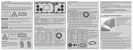
<strong>EDS</strong>-...-FAEB18...30 VDC+U B_If the signal is monitored with a voltmeterthe load resistor R Lis dimensioned in accordancewith the desired output voltageU OUT.Formula: U OUT= R L* I SignalCDI SR LU OUTFig. 24 Signal monitoring with load resistorand voltmeter4.4.3 Model <strong>EDS</strong>-...-ZPower supply and signal output are effected through the 4-contact connector on the hydraulic cylinder. Thepin assignment is shown, see Fig. 25.Pin Assignment Color A 4-pin cable socket for the1 Signal ground brown user-side assembly of yourown connecting cable is2 Power supply + (18 ... 30 VDC) whitepart of the delivery scope.3 Signal (4 ... 20 mA) blue4 Supply ground blackFig. 25 Connection pinassignment, view of solderpin side female cable connectorV+<strong>induSENSOR</strong>, <strong>EDS</strong>Page 30