LOCATOR® BAR ATTACHMENT SYSTEM - Proscan
LOCATOR® BAR ATTACHMENT SYSTEM - Proscan
LOCATOR® BAR ATTACHMENT SYSTEM - Proscan

You also want an ePaper? Increase the reach of your titles
YUMPU automatically turns print PDFs into web optimized ePapers that Google loves.
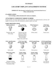
TECHNIQUE<br />
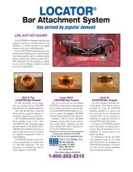
LOCATOR ® <strong>BAR</strong> <strong>ATTACHMENT</strong> <strong>SYSTEM</strong><br />
IMPORTANT: This document contains the most current instructions for use.<br />
Please, read and retain.<br />
CLASSIFICATION:<br />
Universal hinge, resilient attachment for bar splinted endosseous implants.<br />
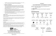
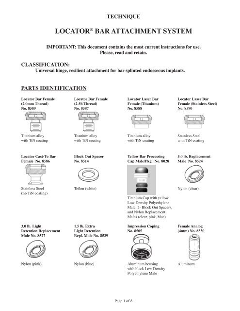
PARTS IDENTIFICATION<br />
Locator Bar Female Locator Bar Female Locator Laser Bar Locator Laser Bar<br />
(2.0mm Thread) (2-56 Thread) Female (Titanium) Female (Stainless Steel)<br />
No. 8589 No. 8587 No. 8588 No. 8590<br />
Titanium alloy Titanium alloy Titanium alloy Stainless Steel<br />
with TiN coating with TiN coating with TiN coating with TiN coating<br />
Locator Cast-To Bar Block Out Spacer Yellow Bar Processing 5.0 lb. Replacement<br />
Female No. 8586 No. 8514 Cap Male/Pkg. No. 8028 Male No. 8524<br />
Stainless Steel Teflon (white) Nylon (clear)<br />
(no TiN coating)<br />
Titanium Cap with yellow<br />
Low Density Polyethylene<br />
Male, 2- Block Out Spacers,<br />
and Nylon Replacement<br />
Males (clear, pink, blue)<br />
3.0 lb. Light 1.5 lb. Extra Impression Coping Female Analog<br />
Retention Replacement Light Retention No. 8505 (4mm) No. 8530<br />
Male No. 8527 Repl. Male No. 8529<br />
Nylon (pink) Nylon (blue) Aluminum housing Aluminum<br />
with black Low Density<br />
Polyethylene Male<br />
Page of 8
Parallel Post Yellow Bar Processing Locator Core Tool Locator Paralleling<br />
No. 8517 Replacement Male No. 8393 Mandrel No. 9107<br />
No. 8026<br />
(Male Removal Tool,<br />
Male Seating Tool, &<br />
gold-plated Abutment Driver)<br />
Low Density<br />
Polyethylene (black)<br />
Low Density<br />
Polyethylene (yellow)<br />
1.7mm Bar Drill 2.0mm Bar Tap 1.8mm Bar Drill 2-56 Bar Tap<br />
(2.0mm Thread) (2.0mm Thread) (2-56 Thread) (2-56 Thread)<br />
No. 9102 No. 9104 No. 9103 No. 9105<br />
Drill & Tap Holder 2.0mm Castable 2-56 Castable<br />
No. 8016 Threaded Insert Threaded Insert<br />
No. 8014 No. 8013<br />
INDICATIONS<br />
The Locator Bar Attachment System is designed for use with overdentures or partial dentures retained in<br />
whole or in part by bar splinted endosseous implants in the mandible or maxilla.<br />
CONTRAINDICATIONS<br />
Not appropriate where a totally rigid connection is required.<br />
CAUTION<br />
Federal (U.S.A.) law restricts this device to sale by or on the order of a licensed dentist.<br />
STERILIZATION<br />
All components and instruments are supplied NON-STERILE. Tools and metal instruments may be<br />
sterilized following standard clinical procedures, prior to use.<br />
FEATURES<br />
1. LOWEST VERTICAL HEIGHT: The total height of the Locator Bar Attachment (abutment plus<br />
male) is only 2.5mm on a cast alloy bar.<br />
2. LOCATING DESIGN: Self-locating design allows a patient to easily seat their overdenture without the<br />
need for accurate alignment of the attachment components.<br />
3. RETENTION INSIDE AND OUT: The patented Dual Retention innovation provides the Locator<br />
Attachment with greater retention surface area than ever before available with other attachments. A<br />
combination of inside and outside retention ensures the longest lasting performance.<br />
4. ROTATIONAL PIVOTING ACTION: The design of the pivoting Locator Male allows a resilient<br />
connection for the prosthesis without any resulting loss of retention. The retentive nylon male remains<br />
Page of 8
completely in contact with the abutment socket while its metal denture cap has a full range of rotational<br />
movement over the male.<br />
5. CHOICE OF FOUR TECHNIQUES: The Locator Bar Attachment can be placed by any of the four<br />
popular techniques used by Dental Laboratories to fabricate an implant retained bar with attachments:<br />
1. Cast a Castable Threaded Insert into a bar for a removable threaded Locator Bar Female connection.<br />
2. Drill and tap the bar for a threaded Locator Bar Female.<br />
3. Laser weld a Locator Laser Bar Female to the bar.<br />
4. Cast-to the stainless steel Locator Cast-To Bar Female with gold alloy.<br />
A. PLACEMENT OF THE LOCATOR <strong>BAR</strong> <strong>ATTACHMENT</strong><br />
The Locator Bar Attachment can be placed by any choice of the four following techniques used by a Dental<br />
Laboratory to fabricate a bar with dental attachments. CAUTION: The most critical consideration in the<br />
proper placement of the Locator Bar Attachment on a milled or cast bar is that a minimum of 1.0mm<br />
of bar material remains between the edge of a UCLA type screw retaining the bar and the Locator<br />
Bar Female, or a minimum of 5.0mm between the edges of multiple placed Locator Bar Females<br />
that is required to avoid interference of the Locator Titanium Denture Caps. (Locator Bar Female =<br />
4.0mm Diameter, Locator Denture Cap = 5.5mm Diameter).<br />
Technique to cast a Castable Threaded Insert into a bar for a removable threaded Locator Bar Female<br />
1. A) Parts needed – New Case:<br />
(8014) 2.0mm Castable Threaded Insert<br />
(8589) Locator Bar Female (2.0mm Thread)<br />
(9104) 2.0mm Bar Tap (2.0mm Thread)<br />
(8016) Drill and Tap Holder<br />
B) Parts needed – Replace TSB Ball Attachment:<br />
(8013) 2-56 Castable Threaded Insert<br />
(8587) Locator Bar Female (2-56 Thread)<br />
(9105) 2-56 Bar Tap (2-56 Thread)<br />
(8016) Drill and Tap Holder<br />
2. The 2.0mm Castable Threaded Insert (Zest order #8014) and a 2.0mm Bar Tap (Zest order #9104) are<br />
used for creating the threaded site in a cast alloy bar.<br />
3. Survey and set a delrin Castable Threaded Insert into the wax pattern of the bar at each site where a<br />
Locator Bar Attachment is needed. The top of the Threaded Insert should be flush with the top surface of<br />
the surrounding bar pattern.<br />
4. The delrin Castable Threaded Insert will become part of the cast alloy bar when the bar pattern is cast<br />
using standard casting procedures.<br />
5. Insert and tighten the 2.0mm Bar Tap into the Drill & Tap Holder (Zest order #8016) and position it into<br />
the handpiece of a precision drilling device. Use the Bar Tap to chase and clean out the cast internal<br />
threads of the attachment site.<br />
6. A special Locator Gold-Plated Abutment Driver (contained in the Locator Core Tool, Zest order #8393)<br />
is designed to engage the inside diameter of the threaded Locator Bar Female and thread it into the bar.<br />
7. Final torque tightening of the Locator Bar Female to prevent screw loosening is achieved using the<br />
20Ncm Torque Wrench (Zest order #4391 Kit). In addition, Locator Torque Wrench Drivers that fit<br />
directly into the Locator Bar Female are available for most brands of torque wrenches.<br />
Technique to drill and tap a bar for a removable threaded Locator Bar Female<br />
1. A) Parts needed – New Case:<br />
(8589) Locator Bar Female (2.0mm Thread)<br />
(9102) 1.7mm Bar Drill (2.0mm Thread)<br />
(9104) 2.0mm Bar Tap (2.0mm Thread)<br />
Page of 8
(8016) Drill & Tap Holder<br />
B) Parts needed – Replace TSB Ball Attachment:<br />
(8587) Locator Bar Female (2-56 Thread)<br />
(9103) 1.8mm Bar Drill (2-56 Thread)<br />
(9105) 2-56 Bar Tap (2-56 Thread)<br />
(8016) Drill & Tap Holder<br />
2. The 1.7mm Bar Drill (Zest order #9102) and a 2.0mm Bar Tap (Zest order #9104) are used for creating<br />
the threaded site in a titanium bar or cast alloy bar. First use a round carbide bur to create a dimple into<br />
the top of the bar at the exact site of the planned preparation.<br />
3. Insert and tighten the 1.7mm Bar Drill into the Drill & Tap Holder (Zest order #8016) and position<br />
it into the handpiece of a precision drilling device. Use the 1.7mm Bar Drill to create the exact size<br />
diameter hole to a depth of 2.8mm that is needed for tapping the site.<br />
4. Place the 2.0mm Bar Tap into the Drill & Tap Holder and position it into the handpiece of a precision<br />
drilling device to create internal threads within the drilled site. The use of tapping fluid while cutting<br />
the threads is required to reduce the chance of breaking the tap off in the preparation.<br />
5. A special Locator Gold-Plated Abutment Driver (contained in the Locator Core Tool, Zest order #8393)<br />
is designed to engage the inside diameter of the threaded Locator Bar Female and thread it into the bar.<br />
6. Final torque tightening of the Locator Bar Female to prevent screw loosening is achieved using the<br />
20Ncm Torque Wrench (Zest order #4391 Kit). In addition, Locator Torque Wrench Drivers that fit<br />
directly into the Locator Bar Female are available for most brands of torque wrenches.<br />
Technique to laser weld a Locator Laser Bar Female on top of a bar<br />
1. A) Parts needed – Laser welding to a titanium bar:<br />
(8588) Locator Laser Bar Female (Titanium)<br />
(9107) Locator Paralleling Mandrel<br />
B) Parts needed – Laser welding to a cast gold alloy bar:<br />
(8590) Locator Laser Bar Female (Stainless Steel)<br />
(9107) Locator Paralleling Mandrel<br />
2. Use the Locator Paralleling Mandrel (Zest order #9107) in a surveyor to place the Laser Bar Female<br />
into position. Insert the split end of the Paralleling Mandrel into the socket of the Laser Bar Female and<br />
tighten the knurled set screw to spread the split portion of the mandrel that will secure the Laser Bar<br />
Female to the mandrel.<br />
3. Tack the Laser Bar Female into place on top of the bar by placing a spot of laser weld on opposite sides<br />
of the female.<br />
4. Remove the Paralleling Mandrel by loosening the knurled set screw. Form a bead of weld around the<br />
entire base circumference of the Laser Bar Female, welding the attachment to the top of the bar.<br />
5. Snap a Locator Yellow Bar Processing Cap Male (Zest order #8028 package) onto the welded Laser Bar<br />
Female to make sure the laser weld does not interfere with the seating of the Locator Denture Cap Male.<br />
Technique for casting-to a Locator Cast-To Bar Female into a gold alloy bar<br />
1. Parts needed – New Case:<br />
(8586) Locator Cast-To Bar Female<br />
(9107) Locator Paralleling Mandrel<br />
2. Use the Locator Paralleling Mandrel (Zest order #9107) in a surveyor to place the Cast-To Bar Female<br />
into the waxed bar in a position that is parallel with other Locator Bar attachments. Insert the split end<br />
of the Paralleling Mandrel into the socket of the Cast-To Bar Female and tighten the knurled set screw to<br />
spread the split portion of the mandrel that will secure the Cast-To Bar Female to the mandrel.<br />
Note: For accurate positioning of the Cast-To Bar Female the Locator Paralleling Mandrel is preferred<br />
to be used in place of the plastic Parallel Post that comes with the attachment, and is removed to use the<br />
Paralleling Mandrel instead.<br />
Page of 8
3. Wax the Cast-to Bar Female directly into the bar. The wax should be built up to the bottom outside<br />
corner on the base of the female, leaving the majority of the outer surface on the base above the top level<br />
of the bar.<br />
4. Remove the Paralleling Mandrel by loosening the knurled set screw, leaving the stainless steel<br />
attachment open for investment material to flow into.<br />
5. Spruing. Run the sprue at a 45 degree angle to the Cast-To Bar Female so the molten gold will flow<br />
down along one side of the female, around and up to the other side. The sprue should not be directed at<br />
the female that could possibly dislodge it when casting.<br />
6. It is recommended to use debubblizer to reduce surface tension during investing procedures.<br />
7. Investing. The most successful castings have been accomplished by using Ceramigold Investment by<br />
Whip Mix Corp. or an equivalent High Heat Investment. Use a casting ring at all times. (Do not use the<br />
ringless technique of investing and casting for the Cast-To Bar Female.)<br />
8. Mix a liquid/powder ratio of Ceramigold using 12ml to 60 grams of powder for each packet of mix<br />
needed. Hand mix for 15 seconds and vacuum mix for 90 seconds at 350-450 RPM. The investment<br />
material should be carefully painted into each attachment cavity to avoid trapping bubbles and to prevent<br />
gold from going inside the female. The remainder of the investment poured into the ring will stabilize<br />
the female during burnout. Place the ring in a water bath for one hour, then bench set for a half hour.<br />
9. Burnout. Place ring in a cold furnace (sprue side down) and raise the temperature to 1500° F maximum.<br />
Use a rate of climb of 0° F to 1500° F maximum over a time period of one hour. Hold at 1500° F<br />
maximum until burnout is complete. (Refer to investment manufacturer’s instructions for suggested<br />
burnout duration.)<br />
10. Casting. Use only precious or semi-precious alloys for casting the stainless steel female into a bar.<br />
Non-precious alloys should not be used. Cast the bar using recommended temperatures of the alloy<br />
manufacturer. The stainless steel Cast-To Bar Female will withstand a temperature of up to 2000° F<br />
without any dimensional change. Do not allow casting temperature to raise above 2000° F which will<br />
melt the stainless steel Bar Female!<br />
11. Divesting. After casting, allow the casting to bench cool for 20 minutes. Be careful to push out the<br />
casting and investment with proper tools. It is not recommended to hammer or bang on rings that may<br />
distort the castings. To remove the investment material from the Cast-To Bar Female without damage to<br />
the stainless steel, use an acid-free investment and porcelain remover solution in an ultrasonic unit for a<br />
period of 30-45 minutes. (Do not use a bur to remove the investment, sandblasting with aluminum<br />
oxide, or an acid pickling solution, all of which can damage the retention surfaces of the Bar<br />
Female attachment.) Clean the bar containing the Locator Cast-To attachment in an ultrasonic cleaner<br />
solution.<br />
12. Finishing and Polishing. When polishing with a rubber wheel, use caution not to damage the Cast-To<br />
Bar Female attachment. Polish the surface of the bar to make a smooth surface. The Locator Parallel<br />
Post (Zest order #8517) can be placed on the female to protect the attachment while polishing. [If<br />
additional polishing of the female attachment is required, it is recommended to only use glass beads at a<br />
low pressure (40 PSI) or a fiberglass or bristle polishing brush.]<br />
13. After polishing the bar, place a Locator Yellow Bar Processing Cap Male (Zest order #8028 package)<br />
onto each Cast-To Bar Female and check for proper fit. Clean again in an ultrasonic solution and deliver<br />
to the dental office.<br />
B. LOCATOR MALE PLACEMENT BY THE DENTIST<br />
1. Placement of the desired type of Locator Bar Female into the bar (see Section A) and delivery of the bar<br />
to the patient must be completed before beginning the procedure for placement of the Locator Male.<br />
2. Place a White Block-Out Spacer (Zest order #8519 Package) over the head of each Locator Bar Female.<br />
The spacer is used to block out the area immediately surrounding the attachment. The space created will<br />
allow the full resilient function of the pivoting metal denture cap over the Locator Male.<br />
Page of 8
NOTE: Due to the additional height required for the Laser Bar Females (Zest order #8588 and<br />
#8590), they require the use of 2 White Block-Out Spacers stacked on top of each other for proper<br />
block out. It is also necessary to block out all undercuts beneath the bar to prevent the added<br />
acrylic resin from locking the denture onto the bar.<br />
3. Insert a Locator Titanium Cap with Yellow Bar Processing Male (Zest order #8028 Package) onto each<br />
Locator Bar Female, leaving the White Block-Out Spacer beneath it. The Yellow Bar Processing Male<br />
will maintain the overdenture in the upper limit of its vertical resiliency during the processing procedure.<br />
4. Prepare a recess in the denture to accommodate the protruding Locator Denture Cap Male. There must<br />
be no contact between the denture and the titanium cap. If the denture rests on the metal cap, excess<br />
pressure on the implant will result.<br />
5. Use the Chairside Dental Attachment Light Cure Kit (Zest order #9403) to light cure bond the Locator<br />
Yellow Bar Denture Cap Male into the denture, or mix a permanent self-curing acrylic and place a small<br />
amount in the recess of the denture and around the metal cap of the Yellow Bar Processing Cap Male.<br />
6. Insert the denture into position in the oral cavity. Guide the patient into occlusion, maintaining a<br />
proper relationship with the opposing arch. Maintain the denture in a passive condition, without<br />
compression of the soft tissue, while the acrylic sets. Excessive occlusal pressure during the setting<br />
time may cause tissue recoil against the denture base and could contribute to dislodging and wear<br />
of the nylon males.<br />
7. After the acrylic resin has cured, remove the denture and discard the white spacer. Use a bur to remove<br />
excess acrylic, and polish the denture base before changing to the final resilient nylon male.<br />
8. Use the Locator Male Removal Tool (attached to the Locator Core Tool, Zest order #8393) to remove<br />
the Yellow Bar Processing Male from the metal denture cap. The sharp circular edge on the end of the<br />
removal tool should be wedged tightly down into the bottom of the Yellow Bar Processing Male so that<br />
it will catch the inside of the yellow plastic insert and pull it at an angle out of the metal housing.<br />
9. The Locator Male Seating Tool (contained in Locator Core Tool, Zest order #8393) is used to firmly<br />
push a Locator Replacement Male into the metal denture cap. The replacement male must seat securely<br />
into place, level with the rim of the cap. Use of multiple Locator attachments (3 or more) in the same<br />
dental arch may require use of the 3.0 lbs. (light retention) pink colored Replacement Male No. 8527,<br />
or 1.5 lbs. (extra light retention) blue colored Replacement Male No. 8529, for easier removal of the<br />
prosthesis by the patient.<br />
NOTE: The Replacement Male will not stay on the tool when it is turned upside down due to the<br />
varying sizes of males available. It is best to hold the denture with the base side down and snap the<br />
male into the metal denture cap.<br />
10. Instruct the patient in the path of insertion. Have the patient insert and remove the appliance several<br />
times.<br />
C. LOCATOR MALE PLACEMENT BY THE LABORATORY<br />
1. Placement of the desired type of Locator Bar Female into the bar must be completed (see Section A)<br />
before beginning the procedure for placement of the Locator Male.<br />
2. Place a Locator Impression Coping with Black Processing Male (Zest order #8505) onto each Locator<br />
Bar Female.<br />
3. Take an impression using a firm body impression material, exercising caution not to compress the<br />
soft tissue. The Locator Impression Coping is designed with minimum retention to be picked up with<br />
the impression material.<br />
4. Snap a Locator Female Analog (Zest order #8530) onto each Impression Coping in the impression. The<br />
analog female must not fall off when turned upside-down with vibration.<br />
5. Pour the master cast. Upon separation, the Locator Female Analog is a part of the master cast replicating<br />
the position of the Locator Bar Female on the bar.<br />
Page of 8
6. Before waxing and processing the appliance, place a Locator Cap with Yellow Bar Processing Male<br />
(Zest order #8028 package) onto each Female Analog in the master cast. Make sure the male is fully<br />
seated.<br />
7. Set the teeth and wax the appliance. Proceed with the processing technique of your choice through the<br />
boil-out step.<br />
8. After the boil-out, remove the Yellow Bar Processing Cap Male. Place a White Block-Out Spacer<br />
(Zest order #8028 package) over the head of each Female Analog. The spacer is used to block out the<br />
immediate area surrounding the Locator Bar Female. The space created will allow the full resilient<br />
function of the pivoting metal denture cap over the Locator Male.<br />
NOTE: Due to the additional height required for the Laser Bar Females (Zest order #8588 and<br />
#8590), they require the use of 2 White Block-Out Spacers stacked on top of each other for proper<br />
block out.<br />
9. Re-insert the Locator Yellow Bar Processing Cap Male onto each Female Analog, leaving the White<br />
Block-Out Spacer beneath it. The Yellow Bar Processing Male will maintain the overdenture in the<br />
upper limit of its vertical resiliency during the processing procedure.<br />
10. Complete the processing and discard the white spacer. Avoid damage to the final male by polishing the<br />
denture base before changing to the final resilient nylon male.<br />
11. Use the Locator Male Removal Tool (attached to the Locator Core Tool, Zest order #8393) to remove<br />
the Yellow Bar Processing Male from the metal denture cap. The sharp circular edge on the end of the<br />
removal tool should be wedged tightly down into the very bottom of the Yellow Bar Processing Male so<br />
that it will catch the inside of the yellow plastic insert and pull it at an angle out of the metal housing.<br />
12. The Locator Male Seating Tool (contained in Locator Core Tool, Zest order #8393) is used to firmly<br />
push a Locator Replacement Male into the empty metal denture cap. The replacement male must seat<br />
securely into place, level with the rim of the cap. Use of multiple Locator attachments (3 or more) in the<br />
same dental arch may require use of the 3.0 lbs. (light retention) pink colored Replacement Male No.<br />
8527, or 1.5 lbs. (extra light retention) blue colored Replacement Male No. 8529, for easier removal of<br />
the prosthesis by the patient.<br />
NOTE: The Replacement Male will not stay on the tool when it is turned upside down due to the<br />
varying sizes of males available. It is best to hold the denture with the base side down and snap the<br />
male into the metal denture cap.<br />
D. HOW TO CHANGE THE LOCATOR MALE<br />
1. The Locator Core Tool, (Zest order #8393) which contains a Locator Male Removal Tool and Locator<br />
Male Seating Tool is used to remove the nylon male from the metal denture cap and replace it with a<br />
Locator Replacement Male.<br />
2. Use the Male Removal Tool attached to the Locator Core Tool to remove the nylon male from the metal<br />
denture cap. The sharp circular edge on the end of the removal tool should be wedged tightly down into<br />
the very bottom of the resilient nylon male so that it will catch the inside of the plastic insert and pull it<br />
at an angle out of the metal housing. To discard the nylon male from the new tip on the Core Tool, point<br />
the tool down and away from you and tighten the new Male Removal Tool clockwise back onto the<br />
Core Tool. This will activate the removal pin and dislodge the nylon male from the tip end of the Male<br />
Removal Tool.<br />
3. The Male Seating Tool is used to firmly push a Locator Replacement Male into the empty metal denture<br />
cap. The replacement male must seat securely into place, level with the rim of the cap. Use of multiple<br />
Locator attachments (3 or more) in the same dental arch may require use of the 3.0 lbs. (light retention)<br />
pink colored Replacement Male No. 8527, or 1.5 lbs. (extra light retention) blue colored Replacement<br />
Male No. 8529, for easier removal of the prosthesis by the patient.<br />
NOTE: The Replacement Male will not stay on the tool when it is turned upside down due to the<br />
varying sizes of males available. It is best to hold the denture with the base side down and snap the<br />
male into the metal denture cap.<br />
Page of 8
E. RELINE AND REBASE<br />
1. Remove each existing nylon male from its metal denture cap following the steps in HOW TO CHANGE<br />
THE LOCATOR MALE (Section D). Replace them with Yellow Bar Processing Replacement Males<br />
(Zest order #8026). The built-in spacer of the Yellow Processing Male will maintain the overdenture in<br />
the same position on the bar as with the original processing, during the reline process.<br />
2. Take a reline impression using the existing overdenture as a tray.<br />
3. The Yellow Bar Processing Males will engage the Locator Bar Females and hold the prosthesis in place<br />
while the impression material sets. When the impression is withdrawn, the Yellow Bar Processing<br />
Replacement Males will remain in the metal denture caps.<br />
4. Snap a Locator Female Analog (Zest order #8530) into each Yellow Bar Processing Male in the<br />
impression and pour a master model.<br />
5. After processing the reline and polishing the denture base, replace the Yellow Bar Processing Males with<br />
the final resilient nylon Locator Replacement Males.<br />
F. PATIENT CARE<br />
Good oral hygiene is vital to implant bar success. The Locator Bar Females must be thoroughly cleaned<br />
daily. The use of a soft nylon bristle or end-tufted toothbrush to clean the attachment, and superfloss to<br />
keep the bar clean of plaque should be taught. A non-abrasive gel toothpaste, and an irrigation system is<br />
recommended to keep the socket of the Locator Bar Female clean.<br />
RETURN POLICY<br />
Check with your Distributor for their policy on returns.<br />
WARRANTY<br />
Zest Anchors, Inc. provides a limited warranty for its products, to the original purchaser, to be free from<br />
defects in workmanship and materials under normal use for a period of one year from the date of purchase.<br />
Zest Anchors, Inc. will, at its option, substitute the returned product that proves to be defective with a<br />
similar product, free of charge.<br />
Zest Anchors, Inc. continually strives to improve its products, and therefore, reserves the right to improve,<br />
modify or discontinue products and components at any time without notice or incurring obligation.<br />
Purchaser assumes all risks and liability resulting from the use of Zest Anchors, Inc. products, whether used<br />
separately or in combination with other products not of Zest Anchors, Inc. manufacture.<br />
ZEST ANCHORS, INC.<br />
2061 Wineridge Place / Escondido, CA 92029 USA<br />
EU AUTHORIZED REPRESENTATIVE<br />
VENTURA IMPLANT AND <strong>ATTACHMENT</strong> <strong>SYSTEM</strong>S<br />
69 The Avenue, Ealing, London, W13 8JR, England<br />
LOCATOR U.S. Patent No. 6,030,219 and 6,299,447.<br />
LOCATOR is a registered trademark of Zest Anchors, Inc.<br />
Illustrations by Ted Suggs<br />
L8003-TM REV D<br />
Page of 8