Zest LOCATOR ROOT ATTACH.qxd - Proscan
Zest LOCATOR ROOT ATTACH.qxd - Proscan
Zest LOCATOR ROOT ATTACH.qxd - Proscan

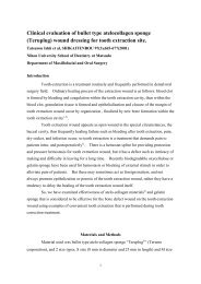
Create successful ePaper yourself
Turn your PDF publications into a flip-book with our unique Google optimized e-Paper software.
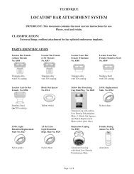
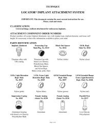
DENTIST). If processing of the denture component by the laboratory is desired, followsteps in “<strong>LOCATOR</strong> MALE PLACEMENT BY THE LABORATORY”.F. RELINE AND REBASE1. Remove each existing nylon male from its metal denture cap following the steps inHOW TO CHANGE THE <strong>LOCATOR</strong> MALE (Section D). Replace them with BlackProcessing Replacement Males (<strong>Zest</strong> order #8515). The built-in spacer of the BlackProcessing Male will maintain the overdenture in its upper level of vertical resiliencyduring the reline process.2. Take a reline impression using the existing overdenture as a tray.3. The Black Processing Males will engage the Locator Females and hold the prosthesis inplace while the impression material sets. When the impression is withdrawn, the BlackProcessing Replacement Males will remain in the metal denture caps.4. Snap a Locator Female Analog (<strong>Zest</strong> order #8516) onto each Black Processing Cap Malein the impression and pour a master model.5. After processing the reline and polishing the denture base, replace the Black ProcessingMales with the final <strong>LOCATOR</strong> Replacement Males.PATIENT CAREExperts recommend that overdenture abutments should be brushed at least once a day with a geltoothpaste to remove plaque and to stimulate gingival tissues, followed by applying a 0.4%Stannous Fluoride gel.The patient should be instructed to periodically visit their dentist for professional cleanings andattachment evaluation. Use plastic instruments for scaling the attachments. Do not use metalinstruments which may create scratches.RETURN POLICYCheck with your Distributor for their policy on returns.WARRANTY<strong>Zest</strong> Anchors, Inc provides a limited warranty for its products, to the original purchaser, to be free fromdefects in workmanship and materials under normal use for a period of one year from the date ofpurchase. <strong>Zest</strong> Anchors, Inc. will, at its option, substitute the returned product that proves to be defectivewith a similar product, free of charge.<strong>Zest</strong> Anchors, Inc. continually strives to improve its products, therefore, reserves the right to improve,modify or discontinue products and components at any time without notice or incurring obligation.Purchaser assumes all risks and liability resulting from the use of <strong>Zest</strong> Anchors, Inc. products whetherused separately or in combination with other products not of <strong>Zest</strong> Anchors, Inc. manufacture.2061 Wineridge Place / Escondido, CA 92029 USAEU AUTHORIZED REPRESENTATIVEVENTURA IMPLANT AND <strong>ATTACH</strong>MENT SYSTEMS69 The Avenue, Ealing, London, W13 8JR, England<strong>LOCATOR</strong> U.S. Patent No. 6,030,219 and 6,299,447. <strong>LOCATOR</strong> is a registered trademark of <strong>Zest</strong> Anchors, Inc.Illustrations by Ted SuggsL8001-TM REV. CTECHNIQUE®<strong>LOCATOR</strong> <strong>ROOT</strong> <strong>ATTACH</strong>MENT SYSTEMIMPORTANT: This document contains the most current instructions for use.Please, read and retain.CLASSIFICATION:Supra-radicular, universal hinge, resilient attachment for endodonticallytreated roots.PARTS IDENTIFICATION0 Degree Female 10 Degree Female 20 Degree Female Cast-to Female Block Out SpacerNo. 8520 No. 8521 No. 8522 No. 8528 No. 8514Stainless Steel Stainless Steel Stainless Steel Stainless Steel Teflonwith TiN coating with TiN coating with TiN coating (no TiN coating) (white)Processing Cap 5.0 lb. Repl. 3.0 lb. Light 1.5 lb. Extra Parallel Post Female AnalogMale/Pkg. No. 8519 Male No. 8524 Retention Repl. Light Retention No. 8517 (5mm) No. 8516Male No. 8527 Repl. Male No. 8529Titanium Cap Nylon (clear) Nylon (pink) Nylon (blue) Low Density Aluminumwith black LowPolyethyleneDensity Polyethylene(black)Male, Block Out Spacer,and Nylon Repl.Males (clear, pink, blue)Pilot Drill Spotface Diamond <strong>LOCATOR</strong>No. 8924 Bur No. 8922 Core Tool No. 8393(Male Removal Tool,Male Seating Tool, &Gold-plated Abutment Driver)Page 1 of 8
INDICATIONSThe <strong>LOCATOR</strong> Root Attachment System is designed for use with overdentures or partialdentures, retained in whole or in part by endodontically treated roots in the mandible or maxilla.CONTRAINDICATIONSNot appropriate where a totally rigid connection is required.CAUTION: Federal (U.S.A.) law restricts this device to sale by or on the order of alicensed dentist.STERILIZATIONAll components and instruments are supplied NON-STERILE. Drills and metal instrumentsmay be sterilized following standard clinical procedures, prior to use.FEATURES1. LOCATING DESIGN: Self-locating design allows a patient to easily seat theiroverdenture without the need for accurate alignment of the attachment components.2. RETENTION INSIDE AND OUTSIDE: The unique Dual Retention innovationprovides the <strong>LOCATOR</strong> attachment with greater retention surface area than ever beforeavailable with other attachments. A combination of inside and outside retention ensuresthe longest lasting performance.3. CHOICE OF ANGLES AND RETENTION: The <strong>LOCATOR</strong> attachment is a supraradiculardesign which consists of the choice of a straight post and two angles (10 and20 degrees) to accommodate divergent roots. Three different retentive males allow foryour choice of regular, light, or extra-light retention according to the needs of thepatient.4. ROTATIONAL PIVOTING ACTION: The design of the pivoting <strong>LOCATOR</strong> Maleallows a resilient connection for the prosthesis without any resulting loss of retention.The retentive nylon male remains completely in contact with the female socket while itsmetal denture cap has a full range of rotational movement over the male.A. PLACEMENT OF THE <strong>LOCATOR</strong> FEMALE1. Prepare and measure study casts to determine the space available in the root for the<strong>LOCATOR</strong> Female. Width of root surface must equal or exceed 4.0mm.2. Decoronate the root and perform endodontic therapy. Remove the desired depth of guttapercha following standard clinical procedures.3. Finish the contouring of the roots. The final reduction should place the root surfacesupragingivally within 1mm of the gingiva. When divergent roots are selected, theocclusal root surfaces should be prepared along the same plane, perpendicular to theintended path of insertion.4. Set the plastic Depth Reference Ring on the Pilot Drill (<strong>Zest</strong> order #8924) to a depthslightly exceeding the length of the female post. (Fig. 1) The post can be shortened ifdesired.5. Size the canal with the Pilot Drill. The alignment of this initial preparation will generallyfollow the direction of the canal. On a non-parallel root, the resulting divergence can becorrected by using an angled <strong>LOCATOR</strong> Female.8. Remove the Parallel Post, leaving the stainless steel attachment open for investmentmaterial to flow into.9. Spruing. Run the sprue at a 45 degree angle to the Cast-To Female so the molten goldwill flow down along one side of the female, around and up to the other side. The sprueshould not be directed at the female which could possibly dislodge it when casting.10. It is recommended to use debubblizer to reduce surface tension during investingprocedures.11. Investing. The most successful castings have been accomplished by using CeramigoldInvestment by Whip Mix Corp. or an equivalent High Heat Investment. Use a castingring at all times. (Do not use the ringless technique of investing and casting for theCast-To Female.)12. Mix a liquid/powder ratio of Ceramigold using 12ml to 60 grams of powder for eachpacket of mix needed. Hand mix for 15 seconds and vacuum mix for 90 seconds at (350-450 RPM). The investment material should be carefully painted into each attachmentcavity to avoid trapping bubbles and to prevent gold from going inside the female. Theremainder of the investment poured into the ring will stabilize the female duringburnout. Place the ring in a water bath for one hour, then bench set for a half hour.13. Burnout. Place ring in a cold furnace (sprue side down) and raise the temperature to1500 F maximum. Use a rate of climb of 0 F to 1500 F maximum over a time period ofone hour. Hold at 1500 F maximum until burnout is complete. (Refer to investmentmanufacturer’s instructions for suggested burnout duration.)14. Casting. Use only precious or semi-precious alloys for casting root copings. Base metalalloys should not be used. Cast the coping using recommended temperatures of the alloymanufacturer. The stainless steel female will withstand a temperature of up to 2000 Fwithout any dimensional change. Do not allow casting temperature to raise above2000 F which will melt the stainless steel female!15. Divesting. After casting, allow all castings to bench cool for 20 minutes. Be careful topush out the casting and investment with proper tools. It is not recommended to hammeror bang on rings which may distort the castings. To remove the investment material fromthe Cast-To Female without damage to the stainless steel, use an acid-free investmentand porcelain remover solution in an ultrasonic unit for a period of 30-45 minutes. (Donot use a bur to remove the investment, sandblasting with aluminum oxide, or anacid pickling solution, all of which can damage the internal socket of the femaleattachment.) Clean the coping containing the <strong>LOCATOR</strong> Cast-To attachment in anultrasonic cleaner solution.16. Finishing and Polishing. When polishing with a rubber wheel, use caution not to damagethe Cast-To Female attachment. Polish the surface of the coping to make a smoothsurface. The <strong>LOCATOR</strong> Parallel Post can be placed on the female to protect theattachment while polishing. (If additional polishing of the female socket is required, it isrecommended to only use glass beads at a low pressure (40 PSI) or a fiberglass or bristlepolishing brush.)17. After polishing the coping, place a <strong>LOCATOR</strong> Processing Cap Male (<strong>Zest</strong> order #8519Package) onto each Cast-To Female and check for proper fit. Clean again in ultrasonicsolution and deliver to the dental office.18. The finished copings containing the <strong>LOCATOR</strong> Cast-To Female are cemented in placeintra-orally on the prepared tooth root.19. For chairside pick-up into the denture of the Locator Black Processing Cap Male (<strong>Zest</strong>order #8519 Package) follow steps in “<strong>LOCATOR</strong> MALE PLACEMENT BY THEPage 2 of 8 Page 7 of 8
Cast-toFemale#8528D. HOW TO CHANGE THE <strong>LOCATOR</strong> MALE1. The <strong>LOCATOR</strong> Core Tool (<strong>Zest</strong> order #8393) which contains a <strong>LOCATOR</strong> MaleRemoval Tool and <strong>LOCATOR</strong> Male Seating Tool is used to remove the nylon male fromthe metal denture cap and replace it with another <strong>LOCATOR</strong> Replacement Male.2. Use the <strong>LOCATOR</strong> Male Removal Tool attached to the Locator Core Tool to remove thenylon male from the metal denture cap. The sharp circular edge on the end of the removaltool should be wedged tightly down into the very bottom of the plastic male so that it willcatch the inside of the plastic insert to pull it at an angle out of the metal housing. Todiscard the nylon male from the new tip on the Core Tool, point the tool down and awayfrom you and tighten the new Male Removal Tool clockwise back onto the Core Tool.This will activate the removal pin and dislodge the nylon male from the tip end of theMale Removal Tool.3. The <strong>LOCATOR</strong> Male Seating Tool is used to firmly push a <strong>LOCATOR</strong> ReplacementMale into the empty metal denture cap. The replacement male must seat securely intoplace, level with the rim of the cap. (Use of multiple Locator attachments (3 or more) inthe same dental arch may require use of the 3.0 lbs. (light retention) pink coloredReplacement Male No. 8527 or 1.5 lbs. (extra light retention) blue colored ReplacementMale No. 8529, for easier removal of the prosthesis by the patient).NOTE: The Replacement Male will not stay on the tool when it is turned upside downdue to the varying sizes of males available. It is best to hold the denture with the baseside down and snap the male into the metal denture cap.E. <strong>LOCATOR</strong> CAST COPINGA special <strong>LOCATOR</strong> Cast-To Female, assembled with Black Parallel Post (<strong>Zest</strong> order#8528) is used for cases where a gold coping is desired to cover and protect the rootsurface. The following procedure is recommended.CAUTION: The danger of root perforation exists when the full length of the PilotDrill is used. Pre-operative radiographic measurement of root length is advised tocompare with the depth set on the Pilot Drill.6. Spotface the root surface using the Diamond Bur (<strong>Zest</strong> order #8922) to a depth where afull 360 degree recessed seat first appears on the occlasal surface of the root. (Fig. 2)When making a countersunk preparation into a divergent root, the depth of thecountersink will vary across the surface of the root. On the shallow side of thepreparation, create the minimum possible recessed seat using the Spotface DiamondBur. (Fig. 3)NOTE: The majority of the outer surface on the base of the <strong>LOCATOR</strong> Female mustremain above the face of the root to allow the male to snap in without interference. (Fig. 4)7. A portion of the original depth from the Pilot Drill canal preparation will be lost due tocountersinking. Re-establish the full depth of the canal preparation by re-preparingwith the Pilot Drill using the original Depth Reference Ring setting.8. Using the <strong>LOCATOR</strong> Parallel Post (<strong>Zest</strong> order #8517) as a handle, place a 0 DegreeFemale into each of the completed preparations to visually approve the proper fit andthe parallel alignment of the multiple attachments. If the alignment of any of theattachments can be improved, select the most suitable angled female (10 or 20 degrees)and rotate it in the preparation to determine its position of optimum parallelism. (Fig. 5)NOTE: A small indexing mark on the female base and the root surface will help toreturn the angle female to the exact position during cementation.9. Cement the <strong>LOCATOR</strong> Females in place with composite resin cement or a strongadhesion material of your choice.10. After the cement has set, round off and polish the root surface from the metal flange tothe tissue. The Parallel Post can be placed over the female to protect it during thepolishing.Pilot Drill#8924Fig. 1SpotfaceDiamondBur #8922Fig. 21. The endodontic treatment must be completed and the remaining tooth structure reducedto the level of the gingiva before beginning the procedure for placement of the<strong>LOCATOR</strong> Cast-To Female. It is desirable that the root be prepared with a beveledshoulder or a chamfer margin.2. Set the plastic Depth Reference Ring on the Pilot Drill (<strong>Zest</strong> order #8924) to a depthslightly exceeding the length of the Cast-To Female post.3. Size the canal with the Pilot Drill. The alignment of this initial preparation will generallyfollow the direction of the canal. On a non-parallel root, the resulting divergence can becorrected by using an angled <strong>LOCATOR</strong> Female.4. Complete the preparation of the site with dental burs of preference to ensure that the castgold coping will completely surround the <strong>LOCATOR</strong> Cast-To Female.NOTE: The majority of the outer surface on the base of the <strong>LOCATOR</strong> Cast-ToFemale must remain above the level of the coping to allow the male to snap inwithout interference.5. An impression is taken being sure to include other attachments or enough anatomy toshow the line of insertion of the denture. The master cast and dies are prepared.6. Using a surveyor, place the plastic Parallel Post with attached Cast-To Female parallelwith other <strong>LOCATOR</strong> attachments.7. Wax the Cast-to Female directly into the die. The wax should be built up to the bottomcorner on the base of the female, leaving the majority of the outer surface on the baseabove the level of the coping.B. <strong>LOCATOR</strong> MALE PLACEMENT BY THE DENTIST1. Cementing of the <strong>LOCATOR</strong> Females and the final root contouring must be completedbefore beginning the procedure for placement of the <strong>LOCATOR</strong> Male.2. Place a White Block-Out Spacer (<strong>Zest</strong> order #8519 Package) over the head of eachcemented female. The spacer is used to block out the remaining exposed surfacesof the root, so that when the denture acrylic is added and cured, it will not come incontact with the root. The space created between the root and the denture base willallow the full resilient function of the pivoting metal denture cap over the <strong>LOCATOR</strong>Male.3. Insert a <strong>LOCATOR</strong> Black Processing Cap Male (<strong>Zest</strong> order #8519 Package) into eachcemented female, leaving the White Block-Out Spacer beneath it. (Fig. 6) The BlackProcessing Male will maintain the overdenture in the upper limit of its verticalresiliency during the processing procedure.Fig. 4 Fig. 5ParallelPost#8517Fig. 3Page 6 of 8 Page 3 of 8
White Block-OutSpacer & ProcessingCap Male#8519 PackageDenture BaseFig. 6Male Removal Tool/Locator Core Tool#8393Fig. 9Male Seating Tool/Locator Core Tool#8393Fig. 104. Prepare a recess in the denture to accommodate the protruding Processing Cap Male.There must be no contact between the denture and the titanium cap. If the denture rests onthe metal cap, excess pressure on the root will be the result.5. Use the Chairside Lightcure Acrylic Resin Kit (<strong>Zest</strong> order #9403) to light cure bond theProcessing Cap Male into the denture (Fig. 7 and 8), or mix a permanent self-curingacrylic and place a small amount in the recess of the denture and around the metal cap ofthe Processing Cap Male.Fig. 7Fig. 86. Insert the denture into position in the oral cavity. Guide the patient into occlusion,maintaining a proper relationship with the opposing arch. Maintain the denture in apassive condition, without compression of the soft tissue while the acrylic sets.Excessive occlusal pressure during the setting time may cause tissue recoil againstthe denture base and could contribute to dislodging and wear of the nylon males.7. After the acrylic resin has cured, remove the denture and discard the white spacer. Use abur to remove excess acrylic and polish the denture base before changing to the final male.8. Use the <strong>LOCATOR</strong> Male Removal Tool (attached to the Locator Core Tool, <strong>Zest</strong> order#8393) to remove the Black Processing Male from the metal denture cap. The sharpcircular edge on the end of the removal tool should be wedged tightly down into the verybottom of the plastic male so that it will catch the inside of the black plastic insert to pullit at an angle out of the metal housing. (Fig. 9) To discard the nylon male from the newtip on the Core Tool, point the tool down and away from you and tighten the new MaleRemoval Tool clockwise back onto the Core Tool. This will activate the removal pin anddislodge the nylon male from the tip end of the Male Removal Tool.9. The <strong>LOCATOR</strong> Male Seating Tool (contained in Locator Core Tool, <strong>Zest</strong> order #8393) isused to firmly push a <strong>LOCATOR</strong> Replacement Male into the empty metal denture cap.(Fig. 10) The replacement male must seat securely into place, level with the rim of thecap. (Fig. 11) Use of multiple Locator attachments (3 or more) in the same dental archmay require use of the 3.0 lbs. (light retention) pink colored Replacement Male No. 8527or 1.5 lbs. (extra light retention) blue colored Replacement Male No. 8529, for easierremoval of the prosthesis by the patient.NOTE: The Replacement Male will not stay on the tool when it is turned upside downdue to the varying sizes of males available. It is best to hold the denture with the baseside down and snap the male into the metal denture cap.10. Instruct the patient in the path of insertion. Have the patient insert and remove theappliance several times.C. <strong>LOCATOR</strong> MALE PLACEMENT BY THE LABORATORY3. Take an impression using a firm body impression material, exercising caution notto compress the soft tissue. (Fig. 12) When the impression is withdrawn, theProcessing Cap Males will remain on the cemented females.4. Remove the Processing Cap Male from each female and snap it onto a <strong>LOCATOR</strong>Female Analog (<strong>Zest</strong> order #8516). Reposition this assembly back into the impressionmaking sure it is fully seated. (Fig. 13)In the Laboratory:5. Pour the master cast. Upon separation, the Female Analog is a part of the master castreplicating the position of the cemented <strong>LOCATOR</strong> Female in the oral cavity.6. Before waxing and processing the appliance place a <strong>LOCATOR</strong> Cap with BlackProcessing Male into each Female Analog in the master cast (Fig. 14). Make sure themale is fully seated.7. Set the teeth and wax the appliance. Proceed with the processing technique of yourchoice through the boil-out step.8. After the boil-out, remove the Processing Cap Male. Place a White Block-Out Spacer(<strong>Zest</strong> order #8519 Package) over the head of each Female Analog. The spacer isused to block out the remaining exposed surfaces of the root, so that the processedacrylic will not come in contact with the root. The space created between the rootand the denture base will allow the full resilient function of the pivoting metal denturecap over the <strong>LOCATOR</strong> Male.9. Re-insert the <strong>LOCATOR</strong> Black Processing Cap Male onto each Female Analog, leavingthe White Block-Out Spacer beneath it. The Black Processing Male will maintain theoverdenture in the upper limit of its vertical resiliency during the processing procedure.10. Complete the processing and discard the white spacer. Avoid damage to the final maleby polishing the denture base before changing to the final male.11. Use the <strong>LOCATOR</strong> Male Removal Tool (attached to the Locator Core Tool, <strong>Zest</strong> order#8393) to remove the Black Processing Male from the metal denture cap. The sharpcircular edge on the end of the removal tool should be wedged tightly down into thevery bottom of the plastic male so that it will catch the inside of the black plastic insertto pull it at an angle out of the metal housing. (Fig. 15)12. The <strong>LOCATOR</strong> Male Seating Tool (contained in Locator Core Tool, <strong>Zest</strong> order #8393)is used to firmly push a <strong>LOCATOR</strong> Replacement Male into the empty metal denturecap. (Fig. 16) The replacement male must seat securely into place, level with the rim ofthe cap. (Fig. 17) Use of multiple Locator attachments (3 or more) in the same dentalarch may require use of the 3.0 lbs. (light retention) pink colored Replacement MaleNo. 8527 or 1.5 lbs. (extra light retention) blue colored Replacement Male No. 8529,for easier removal of the prosthesis by the patient.NOTE: The Replacement Male will not stay on the tool when it is turned upsidedown due to the varying sizes of males available. It is best to hold the denture withthe base side down and snap the male into the metal denture cap.Processing CapMale #8519PackageImpressionMaterialFig. 12Female Analog(5mm) #8516Fig. 13Denture BaseProcessingModelFig. 14Fig. 11In the Operatory:1. Cementing of the <strong>LOCATOR</strong> Females and the final root contouring must be completedbefore beginning the procedure for placement of the <strong>LOCATOR</strong> Male.2. Insert a <strong>LOCATOR</strong> Cap with Black Processing Male (<strong>Zest</strong> order #8519 Package) intoeach cemented female. The built-in spacer of the Black Processing Male will maintain theoverdenture in its upper limit of vertical resiliency during the processing procedure.Fig. 15Page 4 of 8 Fig. 16Page 5 of 8Fig. 17