Research Dossier
Research Dossier
Research Dossier
- No tags were found...

Create successful ePaper yourself
Turn your PDF publications into a flip-book with our unique Google optimized e-Paper software.
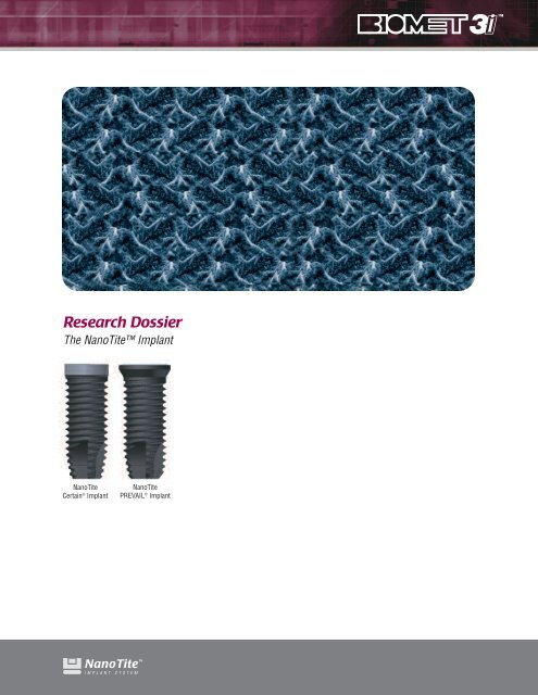
<strong>Research</strong> <strong>Dossier</strong>The NanoTite ImplantNanoTiteCertain ® ImplantNanoTitePREVAIL ® Implant
We are proud to present in this dossier a body of data documenting theperformance of the NanoTite Implant.For more than ten years we have utilized the dual-acid-etchedOSSEOTITE ®Surface treatmenttoimproveourimplant’ssuccess, and more importantlychange the way our customersareabletotreattheirpatients. Before thelaunch of the OSSEOTITE Implant, a two-stageimplantplacementandrestoration procedure requiring a four to six month submerged healing protocolwas the standard approach. The clinical and preclinical studies conducted andpublished on the OSSEOTITE Implant provided insights as to the nature of how dental implantsheal and function general. Clinical investigators found that “early loading” in which implantswere placed in a single-stageapproachandputintofunctionateightweekswasjustassuccessfulasfordelayed-loadingcases. The growing demand by patients and clinicians forimmediatelyloadedrestorationssuggestedthatadditionalsurfaceimprovementsmightbeofclinical benefit.Steve SchiessIn early 2003, research efforts at the UCLA Weintraub Center brought to our attention a nanotechnologythat we have used to further enhance the OSSEOTITE Surface. Throughout the pastfour years, the combined efforts of researchers and clinicians around the globe have allowed forthe accumulation of data to help characterize the effects of the new surface. Contributions fromresearchers at the Universities of Toronto, UCLA, D’Anunzio in Chieti, Italy and elsewhereprovided the product development group at BIOMET 3i the means to validate this technology andlaunch it into commercial introduction as a new dental implant known as the NanoTite Implant.These NanoTite Implant results are compelling and as much as we are interested in the nature ofthese results, we are more concerned with keeping a focus on the benefits we believe can beappreciated by patients and clinicians. By increasing the early fixation of the implant in theosteotomy, we are looking to show that a greater patient sample can be qualified for immediate orearly loading cases, that the overall number of unexplainable failures can be greatly reduced andthat otherwise challenging cases may be made more routine. We hope you find the studies andresults presented herein of interest and helpful for considering how this new technology maybenefit patient care.Steve Schiess, PresidentBIOMET 3i1
Table Of ContentsSurface Characterization StudiesDissolution Of Discrete Calcium Phosphate Crystals From Candidate Ti-based Implant Surfaces ....................................3Surface Area Increase Due To Discrete-Crystalline-Deposition Of Nanometer-scale CaP Crystals ....................................5Roughness Characterization Of Surface With Discrete-Crystalline-Deposition Of Nanometer-scale CaP Crystals..............5Adhesion Shear Strength Of Nanometer-scale CaP Crystals Applied By Discrete-Crystalline-Deposition ..........................6Determination Of CaP Crystal Shear Strength Using Contact-Mode Atomic Force Microscopy (AFM) ..............................7Qualitative Evaluation Of Crystal Adhesion During Implant Placement In Simulated Bone Medium ..................................9Preclinical Animal StudiesDiscrete Calcium Phosphate Nanocrystals Render Titanium Surfaces Bone Bonding ......................................................11Discrete Calcium Phosphate Nanocrystals Enhance Osteoconduction On Titanium-based Implant Surfaces ..................13Nanometer-scale CaP Enhances Early Implant-Bone Fixation In An Animal Model ..........................................................15Discrete Calcium Phosphate Nanocrystalline Deposition Enhances Osteoconduction On Titanium-based Implant Surfaces ..15Discrete Calcium Phosphate Nanocrystals Render Titanium Surfaces Bone Bonding ......................................................16Human Histological StudiesRandomized/Controlled Histological And Histomorphometric Evaluation Of NanoTiteAnd Control Site Evaluation Implants (SEI) In The Human Posterior Maxilla ..................................................................17Overview: Studies In Progress ..............................................................................................................................................18Manuscript Authors....................................................................................................................................................................202
Dissolution Of Discrete Calcium Phosphate Crystals From CandidateTi-based Implant SurfacesPadina Pezeshki, Stanley Lugowski, John E. Davies, Faculty of Dentistry, Institute of Biomaterials andBiomedical Engineering, Faculty of Engineering, University of TorontoCanadian Biomaterials Society25th Annual Meeting (May 26–28, 2006, Calgary, Alberta,Canada)IntroductionPlasma-spraying of dental and orthopedic implants withcalcium phosphate (CaP) was introduced in the mid-1980sas a means of accelerating early peri-implant bone healingand rendering the implant surface bonebonding [1]. While some success has been,and continues to be, achieved clinically;problems have also been identified due todisintegration and delamination of suchrelatively thick (approx. 50 micron) coatings.The latter, due to the high temperature plasmaspraymethod, results in a heterogeneous CaPcoating composition comprising severalpossible CaP phases of differing solubilities.Thus, the solubility of these and other coatingsachieved through biomimetic strategies or solgeltechnology has been a subject ofconsiderable study and different fabricationmethods have aimed to modify the propertiesthat influence the CaP dissolution rate such asphase, particle size, surface area, and porosity[2,3]. Recently, a new means of modifyingmetallic surfaces with CaP has been developedthat comprises the deposition of discretecrystals of CaP from solution onto the metaloxide surface. In suspension the CaP crystalsare of the order of 20-100nms, which can bedeposited on the surface as a function ofimmersion time. Our current study wasdesigned to quantify the amount anddissolution kinetics of these discrete CaPcrystals from Ti6Al4V alloy dental implantsurfaces and compare their behavior withcommercially-available plasma sprayed CaPcoated implants of a similar size. Sinceactivated macrophages and osteoclasts canlocally reduce the extracellular pH to four, wechose an investigational pH range of 4-7 forour experiments.Materials And MethodsTwo Ti6Al4V implant types were employed. TheDCD-treated implants were IOSS615 (6mmdiameter x 15mm length) and plasma sprayedCaP implants were HT 613 (6mm diameter x1.501.000.500.0035.0030.0025.0020.0015.0010.005.000.0013mm length): both supplied by BIOMET 3i in Palm BeachGardens, Florida. Experiments were carried out to (i) measurethe total amount of Ca on the surface of the implants and (ii)the amount of Ca released in pH-specific solutions. In orderto measure the traces of Ca, all experimental equipment wasinitially cleaned to clear Ca contamination. For determinationof total amount of Ca on the surfaces, each DCD-treatedimplant was immersed in 10ml of 1 M Ultrex Grade HCl (pHFigure 1: Comparison of total [Ca] on plasma sprayed and DCD-treated implants4.003.503.002.502.00Ca = -1.9205 pH 3 + 32.805 pH 2 - 188.26 pH + 383.04Ca = 0.0826 pH 3 - 0.9697pH 2 + 1.8537pH + 6.27783 3.5 4 4.5 5 5.5 6 6.5 7 7.5pH3 3.5 4 4.5 5 5.5 6 6.5 7 7.5pHFigure 2: Comparison of different implants’ dissolution response3
0, by JT Baker, Phillipsburg, NJ) for 15minutes and each plasma sprayed samplefor 16 hrs, (n=8). For the second part of theexperiment, samples were placed in 10ml ofsaline solution with fixed pH of 4, 5, 6 or 7(by adding clean HCl or NaOH in a drop-wisefashion) for 15 minutes (n=3). The sampleswere then removed and the total Ca in theremaining solution was measured usingatomic absorption spectrophotometry.Furthermore, the morphology of the surfaceswas qualitatively analyzed using fieldemission scanning electron microscopy(FESEM).4.504.003.503.002.502.001.501.000.500.001 2 3Sample #pH4pH5pH6pH735.00Results And Discussion30.00The results revealed a reproducible25.00difference of three orders of magnitude less20.00in the amount of calcium removed from15.00DCD-treated implants when compared to10.00plasma-sprayed implants (3.81 vs.5.0011551.29 µg respectively) (Figure 1).0.00Moreover, the dissolution of Ca in aspecified time as a function of pHdemonstrated a clear trend between themeasured Ca and the pH of the solution(Figure 2). This is relevant to initial steps ofbiological healing, where activated macrophages, which mayrandomly contact the implant surface, could reduce the localpH to four. Moreover, as the body pH proceeds to its naturalpH of 7.4, the dissolution of CaP from DCD implants isalmost zero, while dissolution does occur from multi-phaseplasma-sprayed implants. Finally, the pH-dependentdissolution of the two implant types were compared and avariation was observed (Figure 3), which demonstrated amore consistent CaP phase for the DCD samples and multiphaseCaP surface for the plasma sprayed samples.ConclusionDCD-treatment provides implants with a more consistent andstable phase of CaP as well as lower amounts of CaP thatwould not invoke the known problems associated withdissolution of CaP from plasma-sprayed coatings.1 2 3Sample #Figure 3: Comparison of distribution of data for the two implant typesReferences1. Sun et al., J Biomed Mater Res. 2001;58(5):570-922. Yang et al., J Biomaterials 2005;26;327-337.3. Zeng et al., J Biomaterials 1999;20(5):443-351pH4pH5pH6pH74
Surface Area Increase Due To Discrete-Crystalline-DepositionOf Nanometer-scale CaP CrystalsZach Suttin, Prabhu Gubbi, BIOMET 3i, Palm Beach Gardens, Florida, USAEuropean Association ForOsseointegration15th Annual Meeting (October 5–7, 2006, Zurich, Switzerland)IntroductionThis study estimates the increase in surface area (SA) dueto the deposition of nano-scale calcium phosphate (CaP)crystals onto a dual-acid-etched (DAE) implant surface.Materials And MethodsAtomic Force Microscopy (AFM) is used to quantify surfacemeasurement parameters of surfaces with nanometertopographical characteristics. In addition to the AFM datacurrently being generated, this study uses theoretical 3-Dmodeling to estimate the SA increase due to the depositionof nano-CaP crystals onto a DAE surface. The size, shapeand distribution of the nano-CaP crystals were based on thedimensions obtained from FESEM (JEOL Model 6700F)images. The crystals were modeled as ellipsoids with sizesranging from 20-80nm on the long axis and 10-39nm on theshort axis. Based on the FESEM imaging, the distributionsof crystal coverage considered for the analysis were classifiedas light (25-30%), medium (55-60%) and heavy (65-70%).Results And DiscussionThe calculated estimates for SA increase due to nano-CaPdeposition were 84%, 152% and 264% for the light, mediumand heavy crystal coverage, respectively. Furthermore,compared to a machined surface, the DAE treatment increasesthe implant SA > 50% (data on file), and it was estimated thatthe increase in implant SA with the addition of nano-CaP ontothe DAE surface ranges from 176% to 446%.ConclusionDeposition of nano-scale CaP crystals over a micron-scaleDAE surface significantly increases the overall SA andtopographical complexity.Percent30025020015010050084%SA Increase152%264%Light Medium HeavyCrystal CoverageRoughness Characterization Of Surface WithDiscrete-Crystalline-Deposition Of Nanometer-scale CaP CrystalsPrabhu Gubbi, Zach Suttin, Alexis Goolik, BIOMET 3i, Palm Beach Gardens, Florida, USAAcademy Of Osseointegration22nd Annual Meeting (March 8-10, 2007, San Antonio, Texas)IntroductionThe objective of this study was to characterize the surfaceroughness of polished titanium disks with nanometer-scalecalcium phosphate (CaP) crystals deposited by a newproprietary surface treatment called discrete-crystallinedeposition(DCD).Materials And MethodsTi (Ti-6Al-4V-ELI) disks, 20mm in diameter and 1.5mm inthickness, were machined and polished on one side to amirror finish (Control group). A group of polished diskswere deposited with nano-scale CaP crystals using the DCDprocess (CaP group). Atomic Force Microscopy (AFM),widely employed to quantify surface measurementparameters of surfaces with nanometer topographicalcharacteristics, was used to obtain surface maps. UsingAFM (Model MMAFM-2, Digital Instruments) in tappingmode, two disks from each group were analyzed withvarious spot sizes. The data were post-processed using a3x3 low filter, with background subtraction, and line by lineaveraging with a 3x3 degree polynomial. The key roughnessparameters obtained were Sq (root mean square variationover the surface) and Sa (absolute mean height deviation).Results And DiscussionThe calculated overall means for the Control group (N = 20data points) were Sq = 5.04nm ± 3.62nm and Sa = 3.29nm± 2.37nm. For the CaP group (N = 18 data points), thecorresponding values were Sq = 19.3nm ± 6.4nm and Sa =14.8nm ± 5.1nm.ConclusionThe surface roughness characterization using AFM suggeststhat the deposition of nanometer-scale CaP crystals over apolished surface substantially increases the topographicalcomplexity.NCM302520151050SqOverall MeansControlCaPSa5
Adhesion Shear Strength Of Nanometer-scale CaP Crystals AppliedBy Discrete-Crystalline-DepositionZach Suttin, Prabhu Gubbi, BIOMET 3i, Palm Beach Gardens, Florida, USAEuropean Association ForOsseointegration15th Annual Meeting (October 5–7, 2006, Zurich, Switzerland)IntroductionIn this study, the adhesion shear strength of nano-scalecalcium phosphate (CaP) crystals deposited onto dual-acidetched(DAE) surfaces was evaluated using Atomic ForceMicroscopy (AFM) and was compared to the shear stress atthe implant-bone interface during implant placement.Materials And MethodsCaP crystals deposited onto CP Ti (n=30) and Ti Alloy(n=30) DAE surfaces were dislodged using contact modeAFM (Model MMAFM-2, Digital Instruments). The adhesionshear strength of each crystal-surface bond was calculatedas the ratio of the maximum shear force supported by thecrystal before separation to the contact area between thecrystal and the surface. In a separate experiment, the torquerequired to place 6mm diameter implants into simulatedbone (polyurethane foam of density 640kg/m 3 ) wasmeasured (n=30) with a Mark-10 digital torque indicator.The average and maximum shear stresses generated at theimplant-bone interface were calculated from the implantinsertion torque values. For additional details, see pages 7-10.Results And DiscussionThe average crystal-surface adhesion shear strength fromAFM analysis was 1.75GPa for CP Ti and 1.52GPa for TiAlloy. The maximum torque for implant placement was17N-Cm, which resulted in an average shear stress of3.61x10 -4 GPa at the implant-bone interface. The maximumshear stress, occurring at the fore threads in the apicalzone, was 5.14x10 -1 GPa.ConclusionThe average crystal-surface adhesion shear strength wasthree orders of magnitude greater than the averageimplant-bone interface shear stress. The results indicatethat the nano-scale CaP crystals deposited onto either CPTi or Ti Alloy DAE surfaces will not dislodge duringimplant placement.Topography of one particleTopography of removed particle(resulting crater)contact areaShear Strength Analysis Using Contact-mode Atomic Force Microscopy (AFM)6
Determination Of CaP Crystal Shear Strength Using Contact-ModeAtomic Force Microscopy (AFM)Gajendra Shekhawat, PhD - <strong>Research</strong> Assistant Professor, Northwestern University Institute of Nanotechnology,Northwestern University, Zach Suttin , BIOMET 3i, Palm Beach Gardens, Florida, USABench TestingAbstractIn a new surface treatment process, discrete nanometer-scalecalcium phosphate (CaP) crystals are bonded to anOSSEOTITE ® Implant surface. The strength of the bondbetween the implant surface and the CaP crystals can be usedas an indicator of the likelihood of the discrete crystalsbecoming dislodged during implant placement. The objectiveof this experiment was to determine the shear strength of thesecrystals deposited on an OSSEOTITE Implant surface usingcontact-mode AFM analysis.BackgroundContact-mode AFM analysis can be used to determine theadhesion strength (e.g., shear strength) of a discretenanometer-scale particle (such as a CaP crystal) bonded toa surface. This analysis uses a nanometer length scale SilicaNitride (SiN) calibrated beam with a diamond coated probe(or tip). The probe is displacement-controlled and theequivalent force is calculated using beam mechanics. Thecontact-mode AFM analysis is initiated by placing the probeon a discrete particle. The beam displacement is slowlyincreased until the displacement load dislodges the particle.For shear strength and compressive strength analysis, theprobe is moved tangential and normal to the surface onwhich the crystal is adhered to. Figure 1 depicts an exampleshear strength contact-mode AFM assay.The results can be used to determine the shear strength ofthe crystal. The shear strength ( s) is a function of:• Force (F)• Contact area (A c )The shear strength can be equated as:s = ___ F ........equation (1)A cThe results for the above experiment shown in (Figure 1) canbe interpreted as follows:Contact Area (A c ) – Since the particle appears to beapproximately 20nm in diameter (relative to the scale), thecontact area between the particle and the surface can,therefore, be reasonably estimated to be between 7.85e -17 m 2and 3.14e -16 m 2 (based on a contact radius of 5nm to 10nm).Shear Force (F) – A 150nN shear force was required todislodge the particle.Shear Strength ( s) – Using equation (1), the shear strengthof the particle can be estimated to be between 4.7x10 -1 GPaand 1.91GPa. The range in shear strength is due to theestimated range of the contact area as described above.Topography of one particleTopography of removed particleFigure 1: Shear strength contact-mode AFM assay7
Materials• Three (3) nanometer-scale CaP crystal processed CP TiOSSEOTITE ® 20mm disks (Control #4543 / Batch #115-72-B)• Three (3) nanometer-scale CaP crystal processed Ti-AlloyOSSEOTITE 20mm disks (Control #4544 / Batch #115-72-B)• Contact-mode AFM (Multimode PicoForce Scanning ProbeMicroscope)Methods• Shear thirty (30) crystals from the CP Ti disks using contactmodeAFM. Acquire the shear force and contact area valuesfor each data point.• Shear thirty (30) crystals from the Ti-Alloy disks contactmodeAFM. Acquire the shear force and contact area valuesfor each data point.The experimental analysiswas conducted by Dr.Gajendra Shekhawat atNorthwestern University’sAtomic and NanoscaleCharacterization ExperimentalCenter (NUANCE).ResultsTable 1 lists the results forthe contact-mode AFManalysis. The force values,which are a function ofbeam displacement, areoutput by the AFM software.The contact area values aremeasured with the AFMfollowing the removal ofeach crystal. The shearstrength was calculatedusing equation (1).The mean, standarddeviation, low and highshear strength valuesfor the nanometer-scaleCaP crystals bonded toboth types of OSSEOTITEsubstrates are shown inTable 2. The crystals on theCP Ti substrate had anaverage strength 15%higher than the crystals onthe Ti Alloy substrate.Table 1: AFM Analysis ResultsCrystal No.Force (nN)Ti AlloyArea (nm^2)Although the main objective of this assay was to determinethe shear strength of the nanometer size CaP crystals, anabbreviated compressive strength assay was subsequentlyconducted. The purpose of this secondary experiment was toverify that the compressive strength of the crystals exceededthe shear strength of the crystals bonded to the OSSEOTITESurface. Four crystals, two from each substrate type, werecompressively loaded with the probe until they fractured. Thecompressive force values required to fracture the crystalsranged from 3.8µN to 6.60x10 2 µN. The 3.8µN value is morethan one order of magnitude greater than the shear force valuesrequired to shear the crystals from the substrate.Shear Strength (GPa)Shear Strength (GPa)Force (nN)Substrate Average Standard Deviation Low HighTi Alloy 1.52 0.29 0.91 1.96CP Ti 1.75 0.3 1.15 2.52CP TiArea (nm^2)Shear Strength (GPa)1 128 137.2 0.93 241 114.3 2.112 166 162.6 1.02 242 141.4 1.713 228 128.2 1.78 236 137.6 1.724 167 143.5 1.16 243 142.3 1.715 188 141.6 1.33 241 167.6 1.446 232 118.4 1.96 242 171.4 1.417 187 118.6 1.58 238 154.6 1.548 202 108.4 1.86 240 124.7 1.929 224 141.7 1.58 231 148.9 1.5510 230 148.4 1.55 242 179.4 1.3511 222 146.6 1.51 243 119.6 2.0312 207 133.5 1.55 236 122.4 1.9313 206 145.5 1.42 241 113.4 2.1314 222 115.6 1.92 237 121.4 1.9515 201 129.6 1.55 242 136.4 1.7716 191 123.3 1.55 252 138.5 1.8217 218 112.7 1.93 237 142.2 1.6718 188 118.2 1.59 256 120.4 2.1319 187 117.2 1.60 254 175.4 1.4520 193 113.4 1.70 253 172.2 1.4721 175 132.6 1.32 296 117.4 2.5222 200 115.6 1.73 258 126.4 2.0423 184 106.6 1.73 269 132.4 2.0324 196 114.7 1.71 241 129.6 1.8625 209 129.5 1.61 222 132.7 1.6726 219 149.5 1.46 249 126.4 1.9727 232 131.2 1.77 221 156.4 1.4128 204 166.8 1.22 219 144 1.5229 222 225 0.99 238 162 1.4730 236 258.8 0.91 279 242 1.15Table 2: Shear Strength Statistics From Table 18
Qualitative Evaluation Of Crystal Adhesion During ImplantPlacement In Simulated Bone MediumZach Suttin, BIOMET 3i, Palm Beach Gardens, Florida, USABench TestingAbstractThe implant-bone interface experiences shear stress duringimplant placement. The objective of this test was toqualitatively measure whether or not nanometer-scale CaPcrystals discretely bonded to OSSEOTITE ® Implants woulddislodge during placement and removal in a simulated bonematerial. Ti- Alloy and CP Ti OSSEOTITE Implants withdiscretely bonded nanometer-scale CaP crystals were placedin and removed from a simulated bone medium. The implantswere then imaged with a field emission scanning electronmicroscope (FE SEM) to determine if the nanometer-scaleCaP crystals had become dislodged. Based on the imagingresults, it is evident that the nanometer-scale CaP crystals didnot become dislodged during implant placement and removal.Materials• Six (6) nanometer-scale CaP crystal processed Ti-Alloy4mm TG FOSS CaP implants (Control #P-84 / Batch #115-68-B)• Six (6) nanometer-scale CaP crystal processed CP Ti 4mmTG FOSS CaP Implants (Control #P-83 / Batch #115-68-B)• 3740 LAST-A-FOAM ®• Medium stiffness toothbrushSTEP 1: Eight (8) blind holes in the 3740 LAST-A-FOAM weredrilled using a 3.25mm twist drill.Figure 1: 3740 LAST-A-FOAM with eight (8) 3.25mm blind holesSTEP 2: Four (4) implants from each group were screwedinto one of the blind holes and then removed.MethodsThe two groups of six (6) implants were used in the experimentas follows:1) Control2) Brush3) Polymer4) Polymer + Brush (1)5) Polymer + Brush (2)6) Polymer + Brush (3)Figure 2: An implant placed in and then removed from a blind holeSTEP 3: Three (3) of the four (4) implants from each groupwhich were screwed into the bone were lightly brushed toremove the polymeric debris.Two of the implants in each group (1 & 2) were not screwedinto the simulated bone medium. The number (1) implantwas used as a control and the number (2) implant was usedto determine if the toothbrush alone would remove the CaPcrystals. Four of the implants from each group (3, 4, 5 & 6)were screwed into and removed from the simulated bonemedium. Implants (4), (5) and (6) were then brushed to tryand remove the simulated bone medium (polymeric material).The number (3) implant was not brushed off so it could beused for comparison to the other implants.Figure 3: An implant placed in a fixture for brushing and thenremoved9
STEP 4: The implants were then imaged using a FESEM atthe apical (in red) and coronal (in green) aspects. The imageswere taken on surfaces at a 45 degree angle relative to theelectron beam direction. The FESEM imaging was performedby Materials Analytical Services, Inc. in Raleigh, NC.Figure 4: Location of acquired FESEM imagesResultsBelow is an example of a 100kX image for the apical andcoronal aspects of one of the twelve (12) implants:“polymer + brush” implants, but it turned out to be difficultto remove the polymer with the brush in most instances.Another difference is that polymeric material can be seenin the “Ti-Alloy + Polymer + Brush (1)” coronal image. Soin this one case some polymeric material agglomerated inthe coronal aspect of the implant (as opposed to just theapical aspect) as well.ConclusionThis assay indicates qualitatively that nanometer-scale CaPcrystals discretely bonded to OSSEOTITE ® Implant surfaceswill not become dislodged during implant placement.Although the nanometer-scale CaP crystals could not be seenon the apical aspect post screw in/out, it is reasonable toassume that the crystals have been covered by the polymer(instead of being sheared off by the polymer) in this area.This argument is supported by considering the image of theapical aspect from the “CP Ti polymer + brush (1)” implant.Ti-Alloy + PolymerApicalCoronalObservations• The “control” implant images show nanometer-scale CaPcrystals in both the apical and coronal aspects.• The “brush” implant images show nanometer-scale CaPcrystals in both the apical and coronal aspects. Thebrushing, therefore, did not remove the nanometer-scaleCaP crystals.• The “polymer” implant images show nanometer-scale CaPcrystals at the coronal aspect and not at the apical aspect.The polymer, therefore, agglomerated at the apical aspectduring implant placement (meaning that the nanometerscaleCaP crystals sheared/collected the polymer). Thenanometer-scale CaP crystals in the coronal aspect did notshear the polymeric material as much as in the apicalaspect since the threads in the coronal aspect are justfollowing the geometry created by the apical threads versusshearing the simulated bone medium.• The “polymer + brush” implant images were similar to the“polymer” implant images. One difference is that in the “CPTi polymer + brush (1)” images the nanometer-scale CaPcrystals in both the apical and coronal aspects can be seen.It was anticipated that this would be the case for all10
Discrete Calcium Phosphate Nanocrystals Render Titanium SurfacesBone Bonding*Vanessa C. Mendes, John E. Davies, Institute of Biomaterials and Biomedical Engineering, Faculty of Dentistry,University of Toronto, OntarioCanadian Biomaterials Society25th Annual Meeting (May 26–28, 2006, Calgary, Alberta,Canada)IntroductionThe surfaces of titanium dental implants have evolved witha variety of microtextures that have been shown to accelerateearly bone healing and increase implant stability [1,2].Specifically, microtextured surfaces of either metallic orcalcium phosphate (CaP) implants have been shown toimprove healing by upregulation of platelet activation [3,4]and increasing fibrin retention to the implant surface; whichare elements necessary to signal, and provide a transientbiological matrix for, osteogenic cell migration to the implantsurface that results in contact osteogenesis [5]. An additionalbenefit of CaP coatings – usually ≥ 50 microns thick – is thatthey have been shown to not only accelerate early healingbut also permit bone bonding to their surfaces. The latter isa benefit unobtainable with metallic surfaces [6].Nevertheless, CaP plasma-sprayed implants also havedemonstrated clinical problems due to delamination andresultant particulate formation in vivo which have led toinflammatory responses and implant failure under loading.For this reason, particularly in the dental implant field, CaPcoatedsurfaces have been largely replaced by microtexturedmetallic surfaces.Recently, it has been shown that it is possible to modify analready clinically successful microtextured metallic surfaceby the deposition of discrete nano-crystals of CaP. Thesedeposited crystals have little effect on the micron-scale textureof the metallic surface, but do superimpose upon it a nanoscaletopographical complexity. Indeed, we show elsewhereat this conference that such discrete CaP crystalline deposits(DCD) can significantly accelerate osteoconduction. Thepurpose of the present study was to design an experimentto ask the question: Can such CaP/DCD render a metallicimplant surface bone-bonding? To address the question, wedesigned custom implants to measure the strength ofattachment of bone to a candidate implant surface.particulate sol-gel deposition method). Thus, a total of fourgroups: cp, cpDCD, alloy, and alloyDCD were generated. Fortyeight implants (12 per group) were placed antero-posteriorlyinto the distal metaphyses of both femora of male Wistar ratsfor nine days. The femora of the sacrificed animals weretrimmed to the width of the implant and placed in sucrosebuffer. The resulting samples consisted of two cortical archesof bone attached to each implant (n=96). For each sample,nylon lines were passed through the marrow spaces betweenthe implant and each cortical arch and the implant wassecured in a vice attached to an Instron Testing Machine(model 8501) (Figure 1).Each nylon line was thenattached to the InstronFrame, displaced at acrosshead speed of30mm/min, and the force torupture the sample wasrecorded. Thus, for eachimplant, two force/displacementresults were generated,one for each femoral arch(medial or lateral). Scanningelectron microscopy (SEM)Figure 1: Preparation of samplefor the tensile test.was used as a qualitative method to analyze the bone/implantinterface following the detachment assay.Results And DiscussionThe post-operative period was uneventful for all rats, exceptone, which had problems load-bearing and was excludedfrom the study. One sample was compromised while beingpositioned in the Instron Machine. Thirty two arches (16 cp,2 cpDCD, 12 alloy and 2 alloyDCD) were insufficientlyattached to the surface of their implant to withstand samplehandling. These data were included in the study. The resulting63 samples were tested as described above. DCD implantsurfaces, either cp or alloy, had statistically significantlygreater average values of detachment force (cp 7.08N andalloy 11.30N) than controls (cp 0.60N and alloy 1.90N)(Figure 2). Furthermore, DAE alloy surfaces exhibitedMaterials And MethodsCustom designed rectangular implants, 6x4x1.5mm, werefabricated from either commercially pure (“cp”) or titaniumalloy (Ti6Al4V or “alloy”). Each implant had a central holedown the long axis to enable suture fixation at surgery. Allimplants were dual-acid-etched (DAE) using either H 2SO 4/HClor HCl/HF for cp and alloy implants respectively. Half of thecp and alloy implants were modified by the CaP/DCD (nominalcrystal size 20nm; surface coverage approx. 50%; modifiedForceTensile Force ValuesFigure 2: Tensile force values for all four groups.*Bone Bonding is the interlocking of bone with the implant surface.11
statistically significant higher detachment force results thanDAE cp. This was expected and could be explained by theenhanced microtopographical complexity of the alloy surfaceas compared to the cp surface.The bone-bonding phenomenonwas demonstrated inthis study by visual inspectionof the samples (Figure 3) andSEM. In samples with high“detachment” forces, thebone arches had fracturedwhile the bone in contact withthe implant surface was notdetached. No such bonebondingwas observed in theDAE samples.Figure 3: Bone-bondingphenomenon.ConclusionDAE implant surfaces can be improved and rendered bonebondingby nano-structured CaP surface modification; andDAE alloy demonstrates greater bone attachment than DAEcp titanium.References1. Buser D, Schenk RK, Steinemann S, Fiorellini JP, FoxCH, Stich H. Influence of surface characteristics onbone integration of titanium implants. Ahistomorphometric study in miniature pigs. J BiomedMater Res 1991;25:889-9022. Gotfredsen K, Wennerberg A, Johansson C, SkovgaardLT, Hjorting-Hansen E. Anchorage of TiO2-blasted,HA-coated, and machined implants: an experimentalstudy with rabbits. J Biomed Mater Res1995;29:1223-313. Park JY, Davies JE. Red blood cell and plateletinteractions with titanium implant surfaces. Clin OralImplant Res 2000;11:530-94. Kikuchi L, Park JY, Victor C, Davies JE Plateletinteractions with calcium phosphate coated surfaces.Biomaterials 2005;26:52855. Davies JE. Understanding peri-implant endosseoushealing. J Dent Educ 2003;67:932-496. Jarcho M, Kay JI, Gummaer RH, Drobeck HP Tissue,cellular and subcellular events at a bone-ceramichydroxylapatite interface. J. Bioeng 1977;1:79Acknowledgements: CIHR Fellowship (VCM), Grants from ORDCFand BIOMET 3i, Palm Beach Gardens, Florida (JED)12
Discrete Calcium Phosphate Nanocrystals EnhanceOsteoconduction On Titanium-based Implant SurfacesVanessa C. Mendes, John E. Davies, Institute of Biomaterials and Biomedical Engineering, Faculty of Dentistry,University of Toronto, OntarioCanadian Biomaterials Society25th Annual Meeting(May 26–28, 2006, Calgary, Alberta, Canada)IntroductionContact osteogenesis, or the apparent growth of bone on (oralong) an implant surface, is the result of bothosteoconduction, which we have defined as the “recruitmentand migration of osteogenic cells”, and the subsequentsecretory activities of these migrated cells which results inthe elaborated bone matrix. The surface microtopography ofimplants has been demonstrated to influence biologicalresponse in the peri-implant compartment and, specifically,to enhance early peri-implant healing and promote increasedbone-implant contact when compared to smooth surfaces. 1,2,3These mechanisms have now been thoroughly documented. 4,5We have previously described a bone-ingrowth chambermodel to quantitatively measure osteoconduction, normallyreferred to as Bone Implant Contact (BIC). 2 However, withoutfurther refinements of the model, we have not, until now,employed this method to compare osteoconduction onmetallic surfaces of essentially similar microtopography. Wedescribe herein, the detailed design of, and refinements to,this miniature bone ingrowth chamber model; the processingtechniques we have developed to derive histological data frommultiple samples in parallel; the block face preparation andback-scattered electron imaging techniques we employ toderive multiple planes of examination from each multiplesample group; and the means of quantitatively analyzing theexperimental results.modified before assembly. On one external surface, a notchwas laser-etched in an angle of 45°, to enable calculation ofthe height of each cross section of the chamber duringsample analysis. All implants were dual-acid-etched (DAE)using either H 2 SO 4 /HCl or HCl/HF for cp and alloy implantsrespectively. Half of the cp and alloy implants were modifiedby the CaP/DCD (nominal crystal size 20nm; surface coverageapprox. 50%; modified particulate sol-gel deposition method).Thus, a total of four groups: cp, cpDCD, alloy and alloyDCDwere generated. Four groups of 25 Tplants of eachexperimental group (total=100), were placed anteroposteriorlyinto the distal metaphyses of both femora of maleWistar rats for nine days (Figure 2). After harvesting,individual samples (Figure 3) were mounted in groups of 10on custom plate holders (Figure 4) and resin embedded forblock-face microscopy (Figure 5). The block surface wasrepeatedly ground (automated polishing machine, EcoMet3000 & AutoMet 200 Power Head, Buehler, IL, USA) toproduce back-scattered electron images (BSEI), followingplatinum sputter coating, of different planes of the implantchamber (Figures 6 and 7). Quantitative analysis of BIC wasperformed with the software Sigma Scan Pro 4 (SPSS Inc.)on >450 micrographs. Single and multiple analysis of variance(ANOVA) were applied to bone contact measurements as afunction of metal (cp vs. alloy) and modification with CaP. Allstatistical analysis were conducted using JMP v5.0.1 software(SAS Institute, Inc., Cary, NC). Statistical significance wasconsidered at p < 0.05 and a Tukey-Kramer HSD post hocanalysis was applied to mean comparisons where indicatedby an overall statistical influence.Our results show that etched titanium alloy is moreosteoconductive than commercially pure titanium. Whenmodified by nano-scale deposits of calcium phosphatecrystals, osteoconduction on both metals is furthersignificantly increased.Materials And MethodsCustom designed T-shaped implants (“Tplants”), 5 x 3 x2mm, were fabricated by BIOMET 3i in Palm Beach Gardens,Florida, USA, from either commercially pure (“cp”) or titaniumalloy (Ti6Al4V or “alloy”). The stem of the “T” is hollow witha cavity 3x2x1mm into which bone could grow followingimplantation (Figure 1). The Tplants are constructed inmodular parts so that their inner walls can be surfaceFigure 1Figure 3Figure 2Figure 413
Figure 5Figure 6 Figure 7Results And DiscussionThe post-operative period was uneventful. In a total of 100femurs, there were 3 fractures. Those samples were excludedfrom the study. Our initial analysis indicated osteoconductionin all groups. Osteoconduction was identified by bone growthalong the walls of the implant. Osteoconduction on both DAE-DCD groups (cpTi and Ti6Al4V) was significantly enhancedin all levels of analysis. This was statistically significant whencompared to the results of DAE groups in all levels of analysis(independent measurements and aggregate measurementsper layer and per implant). Interestingly, when the metals(cpTi or Ti6Al4V) were isolated, it was demonstrated thatthere was no statistical difference between both metals in ananalysis of aggregate measurements per implant. However,statistically significant differences were verified, with respectto increased values of osteoconduction on Ti6Al4V, in ananalysis of either aggregate measurements per layer orindependent bone contact measurements.References1. Buser D, et al (1991) J Biomed Mater Res 25:889-9022. Dziedzic, DM & Davies, JE. 20th Ann Meeting of theSoc. for Biomaterials. April 1994, Boston, USA3. Lazzarra, R.J. et al. (1999) Int. J. PeriodonticsRestorative Dent. 19:117-294. Davies, J.E. (2003) J. Dent. Educ. 67:932-949.5. Davies JE & Hosseini, MM (2000) in: Davies J. E.,Bone Engineering. Toronto: em squared Inc, p. 1-14Acknowledgements: CIHR Fellowship (VCM), Grants from ORDCFand BIOMET 3i, Palm Beach Gardens, Florida (JED)This study has also shown, in a consistent manner, a variationof the amount of bone-implant contact dependent onanatomical location. The proximal side of the chamber hadsignificantly higher bone-implant contact than the distal side.It is suggested that the direction of the vascular supply flow(from proximal to distal) in the rat femur would have beenresponsible for that.ConclusionOur results show that this bone ingrowth model can beemployed to demonstrate the osteoconductive behavior alongsurfaces which display only minor differences in complexityof their microtopography.14
Nanometer-scale CaP Enhances Early Implant-Bone Fixation In AnAnimal ModelJames N. Kenealy, PharmD, Bruce Berckmans, Renée M. Stach, DDS, BIOMET 3i, Palm Beach Gardens,Florida, USAEuropean Association ForOsseointegration15th Annual Meeting (October 5–7, 2006, Zurich, Switzerland)IntroductionThis study used an established rabbit tibia pull-out modelto demonstrate early bone fixation of implants treated witha discrete crystalline deposition (DCD) of nano-scale calciumphosphate (CaP) on a dual-acid-etched (DAE) surface.Materials And MethodsTwenty six-month-old New Zealand white rabbits wereassigned to two treatment groups. Control implants were3.3mmx4mm Ti-6Al-4V-alloy with the DAE surface. Testimplants were of the same design with the addition of DCDnano-scale CaP. One of each implant was surgically placedin the right antereomedial tibia of each rabbit 15mm apart,alternating medial and distal sites between animals.Radiographs were obtained to demonstrate uniformity ofimplant placement. The first treatment group was sacrificedafter two weeks and the second group after three weeks.Each tibia was dissected in whole, mounted and stabilizedin a precision alignment apparatus. A standard Instronmachine (Model #TTMBL)was attached to applytensile forces along thelong axis of the implant.The peak pull-out force todetach the implant frombone was electronicallymeasured and recorded.Results And DiscussionMean peak pull-out forcesfor Test implants were94.0±33.6 N at two weeks17016015014013012011010090807060504030Mean Peak Pull-Out ForcesTestControlTwo WeeksThree Weeksand 145.6±19.8 N at three weeks. Mean forces for Controlimplants are 53.2±24.1 N at two weeks and 93.2±44.9 N atthree weeks and P
Discrete Calcium Phosphate Nanocrystals Render Titanium SurfacesBone BondingVanessa C. Mendes, John E. Davies, Institute of Biomaterials and Biomedical Engineering, Faculty ofDentistry, University of Toronto, OntarioAcademy Of Osseointegration22nd Annual Meeting (March 8-10, 2007, San Antonio, Texas)IntroductionRecently, an already clinically successful microtexturedmetallic surface has been modified by the discrete crystallinedeposition (DCD) of nano-crystals of calcium phosphate(CaP). These deposited crystals have little effect on themicron-scale texture of the metallic surface, but dosuperimpose upon it a nano-scale topographical complexity.The purpose of the present study was to design anexperiment to answer the question: Can such DCD render ametallic implant surface bone-bonding?Materials And MethodsCustom designed rectangular implants, 1.3x2.5x4mm, werefabricated from either commercially pure (cp) or titaniumalloy (Ti6Al4V or Ti64). Implants were either dual-acid-etched(DAE) or treated by a citric acid based process (CAE), andhalf of the implants were modified by the DCD. Eight groupswere generated and implants were placed bilaterally into thefemora of 48 male Wistar rats for nine days. After harvesting,the femora were trimmed to the width of the implant,resulting in two cortical arches of bone attached to eachimplant. The implant was attached an Instron TestingMachine and the arches of bone were distracted at30mm/min. The force to rupture the sample was recorded.Field emission scanning electron microscopy (FE-SEM) wasused to analyze the bone/implant interface followingdetachment.The post-operative period was uneventful except for one rat,which had problems load-bearing and was excluded fromthe study. Two samples were compromised while beingpositioned in the Instron machine. Sixty one arches (16cpDAE, 2 cpDAE-DCD, 12 Ti64DAE, 2 Ti64DAE-DCD, 13cpCAE, 14 Ti64CAE and 2 cpCAE-DCD) were insufficientlyattached to the surface of their implant to withstand handling,and thus were included as zero. The resulting 129 archeswere mechanically tested. DCD surfaces had statisticallysignificantly greater average values of detachment force(cpDAE-DCD 7.08N, Ti96DAE-DCD 11.30N, cpCAE-DCD11.19, Ti64CAE-DCD 9.74) than non-DCD (cpDAE 0.60N,Ti64DAE 1.90N, cpCAE 1.49, Ti64CAE 9.74). The bonebondingphenomenon was visually evident when the corticalarches were fractured and the bone/implant interfaceremained intact. Globular accretions similar to those ofcement lines were observed microscopically, by FE-SEM,interdigitating with the surface of the implant. We concludethat titanium implant surfaces can be improved and renderedbone-bonding by nano-structured CaP surface modification.20181614121086420ControlDCDTensile TestDAE TiCP CAE Ti64 DAE Ti64 CAE TiCP16
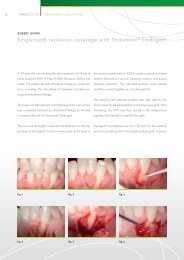
Randomized/Controlled Histological And HistomorphometricEvaluation Of NanoTite TM And Control Site Evaluation Implants (SEI)In The Human Posterior Maxilla*Giovanna Orsini, Maurizio Piattelli, Antonio Scarano, Giovanna Petrone, James Kenealy, Adriano Piattelli,Sergio Caputi - Accepted for Oral Presentation University Foundation and Department of Stomatology andOral Science, University of Chieti-Pescara, ItalyAcademy Of Osseointegration22nd Annual Meeting (March 8-10, 2007, San Antonio, Texas)IntroductionPlacement of dental implants in the posterior maxilla has beenassociated with higher rates of failure due in part to the poorbone quality in this region. Implant osseointegration has beenimproved by introducing different surface treatments. Thepurpose of the present study is the histological andhistomorphometric evaluation of bone formed around a newimplant surface that is created by a deposition of nanometersizedcalcium phosphate particles added to the OSSEOTITE ®Dual-acid-etched surface.Materials And MethodsOne Test (NanoTite) and one Control (OSSEOTITE) custom-made2mm x 10mm site evaluation implants (SEI) were placed in theposterior maxilla of 15 patients. All SEIs were retrieved after twomonths and evaluated under light microscopy and confocal laserscanning microscopy (CLSM) for histomorphometric analysisof the bone-implant contact (BIC).Results And DiscussionThe mean BIC values for Test and Control SEIs are 32.2±18.5%and 19±14.2% respectfully. A statistical analysis of this 70%difference between BIC values for Test and Control implants issignificant at the p
Overview: Studies In ProgressThe following clinical protocols are either ongoing or about to be launched. A brief description of theproject and its goals and objectives are described:NanoTite Clinical <strong>Research</strong> Activity - translating preclinical results to clinical benefitsPreclinical and bench-top studies offer opportunities for determining differences between various prototype designs. Thepreclinical studies from UCLA and The University of Toronto go a long way to confirming that the addition of the DiscreteCrystalline Deposition Treatment imparts a substantive improvement as compared to standard OSSEOTITE ® .But will this matter in clinical cases? What exactly can we look to offer in terms of benefits to the clinician and patient?These and other studies to follow will provide evidenced-based data to allow clinicians to understand how they can deriveadditional benefit from BIOMET 3i NanoTite Implants. What follows are the various ongoing research activities beingconducted on the NanoTite Implant.Immediate Loading – Study 2601 is a prospectiveobservational study of NanoTite PREVAIL ® Implants usedfor immediate loading of single tooth restorations andunilateral bridge cases. The goal of this project is to recruit,treat and monitor the progress of a large group of patientshaving a provisional restoration attached within 48 hours.Fifteen study centers located in North America, Europeand Australia participate in this five year clinical trial. Theenrollment phase is now complete and the interim resultsare providing the reassurance that was hoped for inbringing the benefits of immediate loading with the sameoverall implant success rates observed for early- anddelayed-loading cases. A manuscript of the initial resultsis being prepared for publication.As of Dec 31, 2006, 145 patients having 189 casessupported by 282 implants are being monitored withover 74 patients having exceeded 12 weeks of on-goingevaluation. Case distribution is: short-span bridgerestorations (53%), single tooth replacements (24%)and long-span unilateral bridges of five units or greater(13%). Six implants have been reported as failuresresulting in a 97.8% overall success rate. As three of thesix were the result of an immediate post-surgicalinfection in one patient, the cumulative success rate postrestorationis 98.9%.100%95%90%85%80%75%70%65%60%55%50%97.8%CumulativeSuccess Rate –All Implants98.9%CumulativeSuccess Rate –Post-RestorationLong-spanUnilateral Bridges13%Single ToothReplacements24%Short-span BridgeRestorations63%Cumulative Success RatesNanoTite PREVAIL Implant Cases Under Evaluation18
Overview: Studies In ProgressHuman Clinical StudiesFully Edentulous Maxilla – Study 2607 is a prospective,randomized-controlled study of fully edentulous maxillapatients where cases will be randomly assigned to receiveeither the NanoTite or OSSEOTITE ® Surface Implant. Thestudy will assess the integration success and duration offailure-free function of all implants to determine if theNanoTite Surface enhancement can improve performance infully edentulous maxillary cases.Placement In Augmented Bone – Study 2604 is aprospective, randomized-controlled comparison of NanoTitePREVAIL ® Implants used in sinus lift augmentation sites. Thegoal of this multicenter study is to determine if the NanoTiteSurfaced Implants placed simultaneously with the sinusaugmentation graft material have the same success outcomesas do NanoTite Implants placed into healed sinusaugmentation grafts. When this is established, there will bethe opportunity to avoid four months of delay in functionalizingsuch sinus augmentation cases.Immediate Replacement In Extraction Sites – Study2605 is a prospective, randomized-controlled study ofpatients with multiple tooth extractions where at least twosites will be randomly assigned to receive either the NanoTiteor OSSEOTITE Surface PREVAIL Implant. The study willassess the integration success and duration of failure-freefunction of all implants to determine if the NanoTite Surfaceenhancement can improve performance in these morechallenging cases.Sinus Augmentation Avoidance Trials – Studies 2611and 2612 will utilize a 7mm length NanoTite Surface Implant(actual length – other “short implants are actually 7mm orlonger) to be used in thin maxillary cases where a sinusaugmentation (and standard length implants) would beutilized. In addition to assessing integration and duration offailure-free performance of these short implants, a specificeffort will be made to quantify the amount of resources(clinician and patient time and discomfort, surgical costs,materials costs) that can be preserved by obviating the needfor an augmentation surgery.Clinical Comparisons Of NanoTite Vs. OSSEOTITEHistomorphometric Outcomes –University G. d’Annunzio, Chieti-Pescara University, ItalyMiniplants of 2mm diameter and 10mm length are placed inthe posterior maxilla at sites that will later receive clinicalimplants are retrieved after about two months healing andsubjected to histological analysis of bone-to-implant contact.NanoTite and OSSEOTITE Surfaced Miniplants are placed inthe same patient to provide patient-controlled outcomes.Results of this accepted for presentation at the upcomingAcademy of Osseointegration 2007 Symposia in San Antonio.Biomaterials Clinical <strong>Research</strong> Association, Pescara, ItalyNanoTite and OSSEOTITE Surfaced Miniplants placed in theposterior maxilla and retrieved after two months healing areprocessed for histological analysis of bone-to-implant contact.Animal Pre-Clinical StudiesSoft And Hard Tissue Analysis Of NanoTite AndOSSEOTITE Implant Surfaces –The Sahlgrenska Academy at Göteborg UniversityEight implant sites in each of six canine animals are randomlyassigned to receive either NanoTite or OSSEOTITETransgingival Implants where the surfaces extend from theapex to the coronal seating platform. After two and fourweeks of healing, the interfacial tissues are examined byground section and by a fractionation method that allowsobservation of microcellular structures.Soft And Hard Tissue Analysis Of NanoTite AndOSSEOTITE Implant Surfaces –A collaborative research effort of the Universities of Madrid,Sienna and GöteborgFour implant sites in each of six canine animals are randomlyassigned to receive either NanoTite or OSSEOTITE Implantsthat are placed in a single-stage manner with correspondingNanoTite and OSSEOTITE Healing abutments. After two andfour weeks of healing, the interfacial tissues are examinedby ground section and by a fractionation method that allowsobservation of microcellular structures.Implant Stability – Study 2610 is a randomized, doubleblindevaluation of the impact of a surface modification on theImplant Stability Quotient during the initial implant healingperiod. This prospective, double blind, randomized-controlledclinical study will evaluate changes in the implant stabilityquotient (ISQ) that take place within the first eight weeksfollowing implant placement in the posterior mandible andmaxilla to determine if a difference in the ISQ measurementsare detected between OSSEOTITE and NanoTite Implants.19
Manuscript Authors:Operative Unit of Stomatology and OralScience of Ce.S.I.“G. d’Annunzio” University Foundation andDepartment of Stomatology and Oral Science,University of Chieti-Pescara, ItalyGiovanna Orsini, DDS, PhD<strong>Research</strong> FellowMaurizio Piattelli, MD, DDSProfessor of Oral SurgeryAntonio Scarano, DDS, MD<strong>Research</strong>erGiovanna Petrone, DD, PhD<strong>Research</strong>erAdriano Piattelli, MD, DDSProfessor of Oral Pathology and MedicineSergio Caputi, MD, DDSProfessor of ProsthodonticsUniversity of TorontoInstitute of Biomaterials & Biomedical Engineering,Toronto, CanadaVanessa C. Mendes, DDS, PhDPostdoctoral <strong>Research</strong> FellowJohn E. Davies, BDS, PhD, DScProfessorPadina Pezeshki, BScGraduate StudentStanley Lugowski, PhD<strong>Research</strong> ScientistNorthwestern UniversityNorthwestern University Institute of Nanotechnology,Evanston, IllinoisGajendra Shekhawat, PhD<strong>Research</strong> Assistant ProfessorBIOMET 3iPalm Beach Gardens, Florida, USABruce BerckmansDirector, <strong>Research</strong> and DevelopmentAlexis Goolik, MSEEngineer, Product DevelopmentDr. Prabhu Gubbi, PhDSenior Materials ScientistJames N. Kenealy, PharmDDirector, Clinical <strong>Research</strong> DepartmentDr. Renée M. Stach, DDSMedical Writer, Clinical <strong>Research</strong> DepartmentZach Suttin, MSMEProject Manager, Product Development20
21NOTES
NOTES22
Global Headquarters4555 Riverside DrivePalm Beach Gardens, FL 334101-800-342-5454Outside The U.S.: +1-561-776-6700Fax: +1-561-776-1272www.biomet3i.comSign Up For BIOMET 3i’s Electronic Newsletter “3innovations.”Simply Go Online To www.3i-online.com/signupOSSEOTITE is a registered trademark and Bone Bonding and NanoTite are trademarks of Implant Innovations, Inc. BIOMET 3i andART990design are trademarks and BIOMET is a registered trademark of BIOMET, Inc. LAST-A-FOAM is a registered trademark of GeneralPlastics Manufacturing Company. ©2007 Implant Innovations. All rights reserved. REV A 02/07