HR100-CT Installation Instructions - Hotron
HR100-CT Installation Instructions - Hotron
HR100-CT Installation Instructions - Hotron

Create successful ePaper yourself
Turn your PDF publications into a flip-book with our unique Google optimized e-Paper software.
<strong>HR100</strong>-<strong>CT</strong><br />
User Manual (Original)<br />
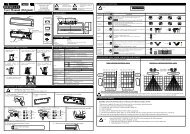
1. DESCRIPTION<br />
Depth Adjustment<br />
Lever Arm<br />
(Inner 3 Rows)<br />
Mounting height of<br />
3m (9.84ft) or lower<br />
Potentiometer<br />
(Sensitivity Volume)<br />
Connector<br />
Indicator LED<br />
(Red & Green)<br />
3.0m<br />
(9.84ft)<br />
English<br />
Area Mask<br />
(Inner 3 Rows)<br />
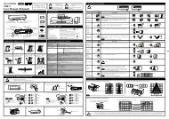
4. MOUNTING PRECAUTIONS<br />
If the sensor is exposed<br />
to excessive rain install<br />
with a <strong>Hotron</strong> weather<br />
cover<br />
Mount within 50mm of the<br />
bottom of the door engine<br />
cover<br />
Max 50mm<br />
If possible ensure no<br />
accumulation of snow or<br />
water on the floor.<br />
Attach the mounting template so that its bottom<br />
edge is flush with the bottom edge of the door engine<br />
cover.<br />
Cover<br />
Dip Switch Y<br />
Dip Switch X<br />
50mm<br />
Detection Window<br />
Area Mask<br />
(Outer 2 Rows)<br />
Ensure there are no<br />
moving objects in the<br />
detection zone<br />
6. MOUNTING & WIRING INFORMATION<br />
Drilling may cause electric shock.<br />
Be careful of hidden wires inside the door engine cover.<br />
50mm<br />
COMPLIED STANDARDS<br />
DIN18650-1:2005<br />
EN 12978:2003<br />
Depth Adjustment<br />
Lever Arm<br />
(Outer 2 Rows)<br />
Ensure the minimum of<br />
reflected sunlight from<br />
the floor<br />
Base<br />
Drill mounting (3.5mmφ) and<br />
wiring (10mmφ) holes.<br />
Accessories<br />
Mounting Template<br />
<strong>Installation</strong><br />
Instruction<br />
Green<br />
Standby<br />
Green blinking<br />
Doorway Learning (When dip switch X 7 is ON)<br />
Red<br />
Detecting<br />
Orange<br />
Detection row “ROW1”(“ROW2” when doorway<br />
Learning is turned ON) is detecting door movement.<br />
Orange blinking (Fast) Indicates a change of dip switch settings<br />
Orange blinking (Slow) Setting Mode is turned ON (When dip switch Y 7 is ON)<br />
Green/Red blinking (Fast) Internal Sensor Error<br />
Green/Red blinking (Slow) Reflected infrared signal from the floor is very low<br />
If you need to remove the sensor body from its base<br />
then lift the sensor body from the base and tilt it<br />
forward to remove as illustrated.<br />
1<br />
5-1 Wiring to a door controller that can test the sensor 5-2 Wiring to a door controller that cannot test the sensor<br />
Red<br />
AC/DC Power<br />
Red<br />
12 to 24 [V]<br />
Sensor’s<br />
Cable Black<br />
±10% (Non Pole)<br />
Sensor’s<br />
Cable Black<br />
Cable<br />
Cable<br />
White<br />
N.O. R2,3,4,5<br />
White<br />
Green<br />
COM Output<br />
Green<br />
Note DIN<br />
Note<br />
Yellow(+)<br />
Collector R1,2<br />
Yellow(+)<br />
Set “Test input” dip switch<br />
Emitter Output<br />
Set “Test input” dip switch<br />
setting Y 4 to “Low”<br />
Blue(-)<br />
setting 4 to “High”<br />
Blue(-)<br />
Y<br />
Ref section 7, Dip Switch High<br />
Gray(+)<br />
Test-P<br />
Ref section 7, Dip Switch High<br />
Gray(+)<br />
Settings.<br />
Y<br />
Test Input<br />
Settings.<br />
Test-N<br />
Low<br />
Brown(-)<br />
Y<br />
Low<br />
Brown(-)<br />
4<br />
4<br />
Cable<br />
Mounting Screws<br />
(2 pcs.)<br />
Ensure no condensation<br />
gets onto the sensor.<br />
Use different frequency<br />
settings for sensors in<br />
close proximity<br />
A B<br />
To maximize the effectiveness of doorway detection, install the <strong>HR100</strong>-<strong>CT</strong> outside and inside as shown below.<br />
Side View<br />
A B<br />
Plan View<br />
A<br />
!<br />
WARNING<br />
6 House connectors in the space provided.<br />
Moving Door Leaf<br />
7 Replace Cover.<br />
B<br />
Moving Door Leaf<br />
Depth<br />
Adjustment<br />
Lever Arm<br />
!<br />
WARNING Disregarding this<br />
symbol may result in<br />
serious injury or death<br />
Special attention is required<br />
Note<br />
when this symbol is shown<br />
2. DIMENSIONS<br />
3. LED INDICATORS<br />
DIN<br />
5. TECHNICAL SPECIFICATIONS<br />
Model Name<br />
Detection Method<br />
<strong>Installation</strong> Height<br />
Supply Voltage<br />
Power Consumption<br />
Output Holding Time<br />
Response Time<br />
Presence Timer<br />
Output<br />
2<br />
!<br />
CAUTION<br />
!<br />
75mm(2.95") = Standard Mounting Pitch<br />
230mm(9.06")<br />
Disregarding this symbol may<br />
CAUTION<br />
result in injury or damage to<br />
equipment<br />
Setting required to conform with<br />
DIN18650<br />
<strong>HR100</strong>-<strong>CT</strong><br />
Active Infrared Reflection<br />
3.0[m] (9.84 [ft]) Max<br />
AC/DC 12 to 24 [V] ±10% 50/60Hz<br />
AC12V-2.1 [VA] (Max) AC24V-2.1 [VA] (Max)<br />
DC12V-110 [mA] (Max) DC24V-60 [mA] (Max)<br />
Approx 0.5s<br />
0.1s ~ 0.2s<br />
Outer 2 Rows 1 [seconds]<br />
Inner 3 Rows 2s,30s,60s or ∞<br />
ROW 1,2<br />
44mm<br />
(1.73")<br />
Attach the sensor with the<br />
mounting screws provided<br />
AC/DC Power<br />
12 to 24 [V]<br />
±10% (Non Pole)<br />
N.O. R2,3,4,5<br />
COM Output<br />
Collector R1,2<br />
Emitter Output<br />
do not connect<br />
do not connect<br />
Be careful not to inadvertantly move the Depth Adjustment<br />
Lever Arms when replacing the cover.<br />
66.5 mm(2.62")<br />
33.5 mm<br />
(1.32")<br />
ROW 2,3,4,5 Form A Relay DC50 [V] 0.1[A] Resistor Load<br />
Test Input<br />
6 [mA] Max. @ 24 [VDC]<br />
Operating Temperature<br />
Operating humidity<br />
-20 to +60 [Deg.C],(-4 to 140 Deg.F)<br />
Below 80%<br />
IP Rate<br />
IP54 (With Base)<br />
Category 2 , performance level D according to EN ISO 13849-1:2008<br />
Weight<br />
Color<br />
0.55 [lb.] (0.25 [kg])<br />
Black, Silver<br />
Accessories<br />
Cable , Mounting Screw 2pcs.,<br />
Mounting Template, <strong>Installation</strong> Instruction<br />
Notice: Specification may be changed without prior notice.<br />
1<br />
Open collector: 7.5 [mA] (Max) Resistor Load<br />
Opto coupler (NPN)<br />
Voltage: 55 [VDC] Max. Current : 50 [mA] Max.<br />
Dark Current: 100 [nA] Max. (Resistance load)<br />
70.4 mm(2.77")<br />
7. DIP SWITCH SETTINGS<br />
!<br />
Function<br />
Presence<br />
Timer<br />
Quantity of<br />
Detection<br />
Rows<br />
Frequency<br />
Doorway<br />
Learn<br />
Doorway<br />
Sensitivity<br />
Function<br />
Direction<br />
Detection<br />
Relay<br />
Output<br />
Mode<br />
Test Input<br />
Setting<br />
from Door<br />
Controller<br />
Reflection<br />
Diagnostics<br />
Monitor<br />
Mode<br />
Setting<br />
Mode<br />
Inner 3<br />
rows<br />
adjustment<br />
lever arm<br />
Setting Mode: Turn ON the setting mode dip switch Y 7 to change all other dip switch<br />
CAUTION<br />
settings. This will cause the relay to activate, opening the door.<br />
Once dip switch settings are configured, Y 7 should be turned OFF.<br />
☆ = Default Setting<br />
Dip Switch X<br />
☆30s<br />
1 2<br />
☆R5<br />
3 4<br />
☆ A<br />
5 6<br />
☆ OFF<br />
7<br />
☆ Normal<br />
8<br />
☆ OFF<br />
☆ N.O.<br />
2<br />
☆ High<br />
☆ Normal<br />
☆ Normal<br />
1<br />
3<br />
4<br />
5<br />
6<br />
Description<br />
The sensor will detect a stationary object for the preset presence timer<br />
setting on the inner 3 rows.<br />
DIN<br />
The number of rows of detection can be set to 5, 4, 3, 2 depending on<br />
detection area requirements.<br />
When more than two sensors are installed in close proximity to each<br />
other select different frequency settings for each sensor to prevent<br />
cross interference.<br />
Doorway Learn allows the 1 st row of detection to be focused<br />
inside the door close area without the detecting door movement.<br />
Note<br />
When set to “OFF” once the door closes the sensitivity level on the<br />
inner most row of detection drops to zero.<br />
Note<br />
To comply with DIN18650 set the presence timer to 60s or<br />
more<br />
When Doorway Learn is turned ON, the sensitivity level<br />
of the inner row of detection is only at maximum when the<br />
outer rows of detection are activated<br />
Only selectable when “Doorway Learn” above is turned “ON”<br />
Description<br />
When set to ON, pedestrians moving away from the sensor will not be<br />
detected.<br />
For pedestrian safety purposes when “Doorway Learn” is set<br />
Note to ON the 1 st and 2 nd row of detection will detect pedestrian<br />
regardless of direction of movement.<br />
Refer to [11.Timing Chart of events] for full details on Output A and<br />
Output B<br />
When connected to a door controller without a TEST input, set to “High”.<br />
When connected to a door controller with a TEST input, set to “Low”<br />
Refer to [11.Timing Chart of events].<br />
DIN Set to “Low” to comply with DIN18650<br />
A low reflected infrared signal is indicated by a slow flashing Red/Green<br />
LED.<br />
To ignore this low reflection error state, set this dip switch to “Low<br />
Reflection”(ON).<br />
DIN To comply with DIN18650 set to “Normal”<br />
Set to snow in instances where false door activations can result from<br />
blowing snow, leaves or rubbish in the door close area.<br />
1.0 [m]<br />
0.5<br />
0<br />
1.0<br />
Door<br />
2.0<br />
2.2<br />
3.0<br />
Turn ON to configure all other dip switch settings.<br />
When ON the sensor will output a detection signal<br />
and the LED will be Orange blinking (Slow).<br />
Once all other dip switch settings are configured turn<br />
OFF again<br />
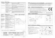
8.DETE<strong>CT</strong>ION AREA WIDTH AND DEPTH ADJUSTMENT<br />
1.5 1.0 [m] 0.5<br />
0 1.5<br />
1.0<br />
[0 degree] setting<br />
!<br />
Detection Area Depth Adjustment: Inner 3 Rows<br />
[m]<br />
0.5<br />
[0 degree] setting<br />
CAUTION<br />
Dip Switch Y<br />
☆ OFF<br />
1.0<br />
Door<br />
2.0<br />
2.2<br />
3.0<br />
0<br />
1.0<br />
Door<br />
2.0<br />
2.2<br />
3.0<br />
7<br />
!<br />
1.0 [m] 0.5<br />
CAUTION<br />
[-8 degree] setting<br />
[-8 degree] setting<br />
Door<br />
0<br />
1.0<br />
2.0<br />
2.2<br />
3.0<br />
With<br />
Base<br />
Without<br />
Base<br />
Detection Area Width Adjustment<br />
Area Mask<br />
(Inner 3 Rows)<br />
Width<br />
2s<br />
1 2<br />
☆R5<br />
3 4<br />
☆ A<br />
5 6<br />
☆ OFF<br />
☆ Normal<br />
☆ OFF<br />
☆ N.O.<br />
N.C.<br />
☆ High<br />
Low<br />
☆ Normal<br />
☆ Normal<br />
Area Mask<br />
(Outer 2 Rows)<br />
Narrow<br />
Wide<br />
2.0 1.0 0 1.0 2.0<br />
Narrow<br />
Wide<br />
1.0<br />
2.0<br />
3.0[m]<br />
ON<br />
5 Rows ON<br />
1 2 3 4 5 6 7 8 1 2 3 4 5 6 7<br />
Dip Switch X<br />
Dip Switch Y<br />
R4<br />
3 4<br />
Door<br />
Possible Setting Options<br />
4 Rows ON<br />
ON<br />
OFF<br />
ON<br />
☆30s<br />
60s<br />
∞<br />
1 2 1 2 1 2<br />
R3<br />
3 4<br />
B<br />
C<br />
D<br />
5 6 5 6 5 6<br />
7 7<br />
8<br />
1<br />
2<br />
4<br />
5<br />
6<br />
Output A (Safety,<br />
Opto-Coupler)<br />
Transmitter<br />
With<br />
Base<br />
Without<br />
Base<br />
IR Spot<br />
Possible Setting Options<br />
Receiver<br />
ON<br />
☆ N.O.<br />
N.C.<br />
Low Ref.<br />
Snow<br />
8<br />
1<br />
3<br />
5<br />
6<br />
3 Rows ON 2 Rows ON<br />
Transmitter<br />
Door<br />
R2<br />
3 4<br />
Output B (Activation,<br />
Mechanical Relay)<br />
IR Spot<br />
Sensitivity zero<br />
Receiver<br />
7<br />
Detection Area Depth Adjustment: Outer 2 Rows<br />
Outer 2 rows<br />
adjustment<br />
lever arm<br />
3.0<br />
2.0 1.0 [m]<br />
[+10 degree] setting<br />
2.0 1.0 [m]<br />
[+10 degree] setting<br />
0<br />
1.0<br />
2.0<br />
2.2<br />
3.0<br />
0<br />
1.0<br />
2.0<br />
2.2<br />
3.0<br />
LED<br />
2.0 1.0 [m]<br />
[0 degree] setting<br />
2.0 1.0 [m]<br />
[0 degree] setting<br />
The above illustrated detection areas represent the actual position of the infrared beams. The actual detection area observed will vary depending on the<br />
sensor installation environment, object been detected and sensor settings. Please ensure that the detection area is set to conform to DIN18650.<br />
☆ OFF<br />
7<br />
Without TEST<br />
High 0v<br />
Low 0v<br />
With TEST<br />
ON<br />
Without TEST<br />
7<br />
0<br />
1.0<br />
2.0<br />
2.2<br />
3.0<br />
0<br />
1.0<br />
2.0<br />
2.2<br />
3.0
9. APPLYING POWER AND THE “DOORWAY LEARN” SETTING<br />
12. DOOR MAINTENANCE WORK<br />
13. SELF DIAGNOSTICS ERRORS<br />
“Doorway Learn” is OFF<br />
Ref section 7, Dip Switch Settings.<br />
Upon power ON, the solid green LED turns on indicating<br />
that the sensor is in standby mode and ready to detect<br />
Green solid LED<br />
X<br />
7<br />
“Doorway Learn” is ON<br />
Ref section 7, Dip Switch Settings.<br />
Upon power ON, the Red LED<br />
indicates a door open relay output<br />
to begin the doorway learn process<br />
X 7<br />
Green LED blinks for 37s as the “door learn” process is carried<br />
out. Door opens/closes<br />
Red solid LED Green blinking LED Green blinking LED<br />
Door learn process complete,<br />
sensor in standby mode<br />
Green solid LED<br />
When carrying out door maintenance work with power applied to the<br />
sensor on door controllers that are wired to “test” the sensor ensure to<br />
set the dip switches as below.<br />
Note<br />
remember to return the dip switch settings to their original<br />
state once door maintenance work has been carried out.<br />
Dip Switch<br />
X<br />
Dip Switch<br />
Y<br />
Technical problems with the <strong>HR100</strong>-<strong>CT</strong> sensor are indicated by a flashing Green/Red LED. The frequency of<br />
flashing indicates the type of problem as explained below<br />
Flash<br />
Frequency<br />
Fast<br />
Green<br />
Red<br />
LED<br />
Cause<br />
Please replace the sensor.<br />
Presence Detection: It takes 10s after sensor power up<br />
for presence detection to be initiated on all rows of<br />
detection.<br />
If before 10s has elapsed someone walks into the detection<br />
area it will take about 5s after the person leaves the<br />
detection zone for presence detection to be functional.<br />
General Caution:<br />
Note<br />
CAUTION<br />
When carrying out the following work, turn off sensor power.<br />
※ When the floor condition is changed by placing a mat on the floor etc.<br />
※ When the detection area pattern or sensor sensitivity is adjusted.<br />
10. VERIFICATION OF OPERATION<br />
After installation is completed “walk test” the sensor detection area to verify its location. If the detection area is not as<br />
expected adjust the detection area as referred to in section 8 or increase the rows of detection using Dip switch X 3 & 4<br />
If the detection area is still not as expected then the sensor sensitivity can be increased by turning the potentiometer<br />
clockwise. When the sensor detects even though there is nothing in the detection area the sensor sensitivity can be<br />
decreased by turning the potentiometer in the anti-clockwise direction.<br />
11. TIMING CHART OF EVENTS<br />
Output A Row 1, 2 / Test Input<br />
Dip Switch Y<br />
Output A setting<br />
Dip Switch Y<br />
N.O.<br />
N.C.<br />
Test Input setting<br />
2<br />
5 4 3 2 1<br />
POWER OFF<br />
High<br />
Low<br />
!<br />
Yellow<br />
Blue<br />
Yellow<br />
Blue<br />
Presence Detection: During the “Doorway Learn” process the outer 4 rows of detection on the <strong>HR100</strong>-<strong>CT</strong> sensor<br />
switch from motion detection to presence detection 10s after power ON. The inner “door learn” row of detection will<br />
switch from motion to presence detection after the “doorway learn” process is carried out.<br />
When Doorway Learn is turned ON, the sensitivity level of the inner row of detection is only at maximum when the outer<br />
rows of detection are activated<br />
5 4 3 2 1<br />
NON-DETE<strong>CT</strong>ION<br />
Test Input<br />
“Doorway Learn” Failure & Recovery: If a person enters the detection area during the “doorway learn” process it<br />
may not be successfully completed. In this case the sensor will carry out the doorway learn process over three door<br />
activations by a person in order to build an accurate image of the door open and door close position.<br />
Yellow<br />
Blue<br />
Yellow<br />
Blue<br />
5 4 3 2 1<br />
DETE<strong>CT</strong>ION<br />
TEST<br />
NON-TEST<br />
Yellow<br />
Blue<br />
Yellow<br />
Blue<br />
5 4 3 2 1<br />
Yellow<br />
Blue<br />
Yellow<br />
Blue<br />
T1<br />
NON-TEST<br />
TEST<br />
Sensitivity<br />
L<br />
NON-DETE<strong>CT</strong>ION<br />
Yellow<br />
Blue<br />
Yellow<br />
Blue<br />
TEST RESPONSE<br />
H<br />
5 4 3 2 1<br />
T2<br />
DETE<strong>CT</strong>ION as<br />
response to TEST<br />
TEST<br />
NON-TEST<br />
Yellow<br />
Blue<br />
Yellow<br />
Blue<br />
ON<br />
1 2 3 4 5 6 7 8<br />
2s<br />
1 2<br />
ON<br />
Refer to [7.Dip Switch Settings].<br />
14. TROUBLESHOOTING<br />
Problem<br />
Door does not open when a<br />
person enters the detection<br />
area<br />
Door opens and closes for no<br />
apparent reason (Ghosting)<br />
When Door opens or closes,<br />
LED ORANGE<br />
Door opens and remains in the<br />
open position<br />
Dip switch settings do not seem<br />
to take effect<br />
1 2 3 4 5 6 7<br />
Low<br />
Ref. 5<br />
Slow<br />
Green<br />
Red<br />
LED Status Possible Cause Solution<br />
Sensor Connector not connected correctly<br />
Tighten or reconnect the connector.<br />
OFF Incorrect power supply voltage<br />
Apply proper voltage to the sensor. (AC/DC 12-24V)<br />
Incorrect sensor wiring<br />
Double check sensor wiring<br />
Remove moving object from detection area.<br />
Door Opens RED Sensitivity too high for the installation environment Reduce the sensor sensitivity setting<br />
Door Closes<br />
Dust, frost or water droplet on the sensor lens<br />
Wipe the sensor lens clean and install a weather cover if necessary<br />
GREEN Detection area overlaps with that of another sensor Ensure different frequency setting for each sensor.<br />
Detection of falling snow, insects, leaves etc<br />
Turn monitor mode Dip switch Y 6 to “snow”<br />
ORANGE<br />
RED<br />
GREEN/RED<br />
FAST FLASH<br />
GREEN/RED<br />
SLOW FLASH<br />
ORANGE blinking<br />
(Slow)<br />
Compiler of Technical File (EC Community)<br />
David Morgan<br />
<strong>Hotron</strong> Ireland Ltd<br />
26 Dublin Street, Carlow, Ireland<br />
Ph: +353-(0)59-9140345 Fax: +353-(0)59-9140543<br />
Above EC Type Directives Certified by:<br />
TUV NORD CERT GmbH<br />
30519 Hannover, Germany<br />
Identification No: 0044<br />
Detection row “ROW1” (“ROW2” when “Doorway<br />
Learn” is turned ON) is focused too close to the door.<br />
Detection area changed, while ∞ infinity<br />
presence timer setting is in use<br />
Incorrect sensor wiring<br />
Reflected signal saturation<br />
Internal sensor error<br />
Reflection of the transmitted infrared signal from<br />
the floor is too low<br />
Setting Mode (Dip switch Y 7 set to ON)<br />
Adjust detection depth for Inner 3 rows away from the door.<br />
Re-power the sensor or change the presence timer settings to 30 or 60 secs<br />
Double check sensor wiring<br />
Remove highly reflective objects from the detection<br />
area, or lower the sensor sensitivity setting<br />
Turn OFF the “setting mode” Dipswitch Y 7<br />
Not Applicable Setting Mode, Dip switch Y 7 not turned ON Turn the “Setting Mode” Dip switch Y 7 to ON<br />
15. <strong>HR100</strong>-<strong>CT</strong> EC DECLARATION OF CONFORMITY<br />
We <strong>Hotron</strong> declare that this sensor complies with all of the applicable EHSRs of Annex I of the Machinery Directive and that<br />
the appropriate conformity assessment procedure has been carried out.<br />
Description of Product:<br />
<strong>HR100</strong>-<strong>CT</strong> Combined motion and presence detection sensor for the activation and safety of automatic doors.<br />
Technology used is Active Infrared Technology<br />
Harmonized Standards Used:<br />
EN ISO 13849-1:2008<br />
Declaration made by<br />
Kaoru Musya<br />
General Manager. Honda Electron<br />
Replace the sensor<br />
Other Technical Standards Used:<br />
DIN 18650-1:2005<br />
Location of Declaration<br />
Honda Electron Co., LTD.<br />
1-23-19 Asahi-Cho, Machida-City,<br />
Tokyo, Japan<br />
Confirm that the sensitivity potentiometer is set to<br />
maximum and re-power the sensor.<br />
If the error persists, set<br />
Dip Switch Y 5 to “Low Reflection”.<br />
Increase sensor sensitivity or change the “Reflection Diagnostics”<br />
Dip switch Y 5 from “Normal” to “Low Ref”<br />
Date<br />
31th of May 2011<br />
Output B Row 2, 3, 4, 5<br />
4<br />
T1 : 10±1 [mSec] App<br />
T2 : 11±1 [mSec] App<br />
Gray<br />
Sensor<br />
Brown<br />
Supplying DC12 to 24V, make current flow from<br />
Gray to Brown.<br />
Gray<br />
Sensor<br />
Brown<br />
Break the current<br />
flow on test state.<br />
Gray<br />
Brown<br />
Sensor<br />
Directives Fulfilled:<br />
DIRE<strong>CT</strong>IVE 2006/42/EC<br />
DIN 18650-1:2005 Powered pedestrian doors Part 1: Product requirements chapter 5.7.4<br />
EN12978:2003 Industrial, commercial and garage doors and gates - safety devices for power operated doors and gates - Requirements and test methods<br />
EN62061:2005 Functional safety of electrical/electronic/programmable electronic safety-related systems<br />
EN ISO 13849-1:2008 Safety of machinery - Safety-related parts of control systems.<br />
< Disclaimer > The manufacturer cannot be held responsible for below.<br />
1. Misinterpretation of the installation instructions, miss connection, negligence, sensor modification and inappropriate installation.<br />
2. Damage caused by inappropriate transportation.<br />
3. Accidents or damages caused by fire, pollution, abnormal voltage, earthquake, thunderstorm, wind, floods and other acts of providence.<br />
4. Losses of business profits, business interruptions, business information losses and other financial losses caused by using the sensor or malfunction of the sensor.<br />
5. Amount of compensation beyond selling price in all cases.<br />
Dip Switch Y<br />
Output B setting<br />
5 4 3 2 1<br />
POWER OFF<br />
5 4 3 2 1 5 4 3 2 1<br />
NON-DETE<strong>CT</strong>ION<br />
DETE<strong>CT</strong>ION<br />
R<br />
N.O.<br />
N.C.<br />
3<br />
Green<br />
White<br />
Green<br />
White<br />
Green<br />
White<br />
Green<br />
White<br />
Green<br />
White<br />
Green<br />
White<br />
Manufacturer<br />
HOTRON CO.,LTD.<br />
1-11-26 Hyakunin-Cho, Shinjuku-Ku, Tokyo, Japan<br />
Phone: +81-(0)3-5330-9221<br />
Fax: +81-(0)3-5330-9222<br />
URL: http://www.hotron.com<br />
SALES Europe<br />
<strong>Hotron</strong> Ireland Ltd.<br />
26 Dublin Street (2nd Floor), Carlow, Ireland<br />
Phone: +353-(0)59-9140345<br />
Fax: +353-(0)59-9140543<br />
URL: http://www.hotron.com<br />
MP-10091-A '11.09<br />
PRINTED IN JAPAN