Domino 1100 Installation Instructions - Hotron
Domino 1100 Installation Instructions - Hotron
Domino 1100 Installation Instructions - Hotron

You also want an ePaper? Increase the reach of your titles
YUMPU automatically turns print PDFs into web optimized ePapers that Google loves.
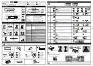
FITTING AND OPERATING INSTRUCTIONSDOMINO <strong>1100</strong> RCDOMINO 1XXX, other versionsRadar motion sensors for the detection of objects for automatic gates.SAFETY INFORMATIONThe unit is only to be operated with voltages that comply with theSafety Extra-Low Voltage (SELV) requirements in safetystandards based on IEC 60950. This unit is only to be installedand maintained by trained, qualified personnel.1. FITTING1.1 OPENING THE RADAR SENSOR UNIT 1.2 DRILLINGfrom the rear, prior to installation from the front, after installation Stick the drilling template in place and drillaccording to the instructions1.3 FASTENING AND CONNECTING-UPDraw the cable through the opening providedConnect the cable to the terminals1 power supply AC/DC brown2 power supply AC/DC green3 Main relay white4 Main relay yellowVehicle relayVehicle relaygreypinkFasten the base plate with the screws contained in the housing,to remove and insert the electronics, observe the instructions in point 2.31.4 OTHER INSTALLATION OPTIONSOptional accessory out of the 4tec accessory range.Ceiling-mounting with mounting bracketorWall fastening with weather-cap set
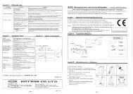
The printed circuit board can also be inserted at a slant angle.Turn maximum 3 steps to the right or to the left!2.5 SIZE OF THE DETECTION AREA / SENSITIVITYThe sensitivity potentiometer control enables the size of thedetection area to be adjusted.high sensitivity = big detection arealow sensitivity = small detection area2. 6 DESCRIPTION OF THE DIFFERENT CONFIGURATION CHARACTERISTICS OF THE RADAR SENSOR UNITDetection characteristicswithout direction recognition (mono)with direction recognition (stereo)mit Richtungserkennung (stereo)forwards / backwardsforwards (towards the radar sensor unit)backwards (away from the radar sensor unit)The direction recognition can completely be switched off. The radar sensor unit will not detect any movements and if the relay contact will be changed nowthe gate remains constant open or closed.Cross traffic fade-outSettings selectively: low, medium or highespecially suited to fittingangles of 25° to 40°If the cross traffic fade-out function is switched on, the gate will open only if themotion is towards the gate.
People- vehicle detectionThe radar is able to analyse motions from people or vehicles different and to switch, according to the settings,the main relay, the vehicle relay or both relay at the same time.Relay functionsThe main relay switches always, that means for people and vehicles detection.The vehicle relay switches only if the vehicle detection is activated and a vehicle will move inside the detection area.Examples of useGate with separate pedestrian door. Gate control unit with 1 input.Vehicle detection activated, only the vehicle relay is connected to the Gate control unitVehicle approaches,vehicle relay switches,(LED fast flashing green/red)gate opensPerson approaches,vehicle relay switches not,Gate remains closed,person uses the pedestrian doorGATE CONTROL UNITmain relaysvehicle relaysDOMINO <strong>1100</strong> RCGate without separate pedestrian door. Gate control unit with 2 inputs.Vehicle detection activated, vehicle relay and main relay are connected to the Gatecontrol unitPerson approaches,main relay switches,(LED lights red)gate opens halfVehicle approaches,vehicle relay switches,(LED fast flashing green/red)gate opens completelyGATE CONTROL UNITmain relaysvehicle relaysDOMINO <strong>1100</strong> RC2.7 LED STATUS DISPLAYgreenredgreen/red fast flashinggreen/red slow flashinggreen flashingred flashingunit ready for operationmain relay activevehicle relay activeinitialisation (for 10 seconds after switching on)command receivederrorLED
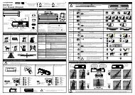
2.8 CONFIGURATION OF THE RADAR SENSOR UNITSETTINGS WITH BUTTONSButton VALUELED green/redButton MENUIR-transmitterIR-receiverProgramming modeThe programming mode allows to adjust the radar sensor unit with two push buttons. All settings can be read out the below programming table.The LED flashing order shows the respective settings.While the programming mode is activated the IR-communication is blocked but the sensor functions are still active.If during 10 minutes no settings have been done the programming mode will be quitted and all settings will be saved automatically.START: Activate programming modePush button MENU for approx. 2s, programming mode is activated LED is flashing. The flashing order shows the actual settings.LED flashing red number corresponding MENU nr. LED flashing green number corresponding VALUE nr.the LED does not flash if the VALUE is = 0STOP: Leave programming modePush button MENU for approx. 2s, programming mode is quitted all settings are automatically savedSet MENU or VALUE → watch programming tablepush button MENU 1x short = increase MENU 1 stepIs the maximum menu nr. reached, the programming starts again with the lowest menu nr., i.e. 1x push = 1 step forwardspush button VALUE 1x short = increase VALUE 1 stepIs the maximum value reached, the programming starts again with the lowest value, i.e. 1x push = 1 step forwardsWhen the MENU or VALUE buttons be pushed, the flashing code stops and restarts flashing with the new value.After each change the setting will be automatically saved.Programming sample: Change the output hold time from 1.0 s to 3.0 spush button MENU approx. 2s = start programmingLED flashing 1x red and 8x green = MENU sensitivity, VALUE 8push button MENU 3xLED flashing 4x red and 3x greenpush button VALUE 3xLED flashing 4x red and 6x greenpush button MENU approx. 2sProgramming table= output hold time VALUE 1.0 s= output hold time VALUE 3.0 s= stop programming, setting automatically savedMENUred LEDflashing according noe.g. 3x red = vehicledetection1Sensitivity2Detection mode3Vehicle detection4Output hold time5Relay contact6Fade out cross traffic7Sensor addressVALUEgreen LEDflashing according value012301230123456781201230 = LED not flashing!1 - 16offstereo forwardsstereo backwardsmonoofflowmediumhighoff0.2s0.5s1.0s1.5s2.0s3.0s4.0s5.0sN.O.N.C.offlowmediumhigh1 – 16DESCRIPTIONStart:push button MENU for approx. 2sStop:push button MENU for approx. 2sReset:push button MENU and VALUE at the same time for approx. 2sLED flashing for approx. 10s green/red1 = lowest sensitivity = small detection area16 = highest sensitivity = big detection areaoff = no detection possibledetects motion towards the radar sensor unitdetects motion away from the radar sensor unitdetects motion forwards and backwardsoff = no detection the vehicle relays does not switchonly vehicles will be detectedthe settings low, medium and high allow to set the sensor accurate according to the localizationoff = relay does not switch0.2s = smallest hold time1.0s = factory setting5.0s = biggest hold timecontact will close by detection detection mode switched off and the change of relay contactcontact will open by detection will keep the gate constant open or closedall movements well be detectedcross traffic will be fade outthe settings low, medium and high allow to set the sensor accurate according to the localizationThe sensor address is needed for the programming with remote control. The address can bechoose and changed with buttons. The sensor address must be changed only if there are morethan one sensor inside the range of the remote control.
SETTINGS WITH REMOTE CONTROL Domi-LINKThe Domi-LINK allows to set the radar sensor unit easy, fast and perfectly from the floor.While the programming the sensor functions are still active. The settings can be checked immediately.Low batteries (shown on the Domi-LINK display), sunlight, fluorescent lamps and wrong orientation of Domi-LINKcan reduce the range and cause transmission errors.For safety reasons the IR-programming mode will be intermitted after 30 min., alternatively completely blocked.To unlock the programming mode, push the MENU or VALUE button at the radar sensor unit or cut the power supply for a few seconds.Establish connectionBefore starting the programming please read the Domi-LINK operating instructions!Sensor switched of and ready for operation, LED is green.Domi-LINK must point frontal at the sensor.For a perfect transmission thesensor angle (0 – 40°) shouldalso be considered.Sensor list<strong>Domino</strong> 100X RC<strong>Domino</strong> 101X RC<strong>Domino</strong> 102X RC<strong>Domino</strong> 110X RC<strong>Domino</strong> 110X RCChoose the <strong>Domino</strong> 110X RC from the sensor list shown at the Domi-LINK LCD-display.After that select the address, only necessary if more than one sensor is inside the range of Domi-LINK.Programming the address → have a look at the settings with buttons.The address can be selected from the list or can be read out with “search address“.The mark show the selected address.√Push the select button to establish a connection to the radar sensor unit.If the connection is established, on LCD display will be shown a list with all settings.The mark shows the current settings.If the sensor is encoded, the display will show “enter code”.The code can be set with the for Domi-LINK push buttons.As soon as the fourth digit has been set the code will be transmitted.If the code is correct a selection list will appear on display.Start settingsThe four push buttons allow to select the desired settings shown on display.With “read value” the current setting can be read out and shown on display. The required value can beselected with the arrow push buttons and confirmed and transmitted with pushing the select button.The mark shows immediately the new value.If the transmission was not OK the error will appear on display and the transmission has to be repeated.The new setting can be read out immediately after the transmission.search addressaddress 1address 2address 3address 4enter code_ _ _ _<strong>Domino</strong> 110X RCSensitivityDetection modeVehicle detectionOutput hold timeRelays contactFade out cross trafficSensitivityread value1 min234Programming table Domi-LINKMENU SETTINGS DESCRIPTIONSensitivity 1 – 16 1 = lowest sensitivity = small detection area16 = highest sensitivity = big detection areaDetection modeVehicle detectionOutput hold timeRelay contactFade out cross trafficResetCodeDisconnectoffstereo forwardsstereo backwardsmonoofflowmediumhighoff0.2s0.5s1.0s1.5s2.0s3.0s4.0s5.0sN.O.N.C.offlowmediumhighaccess with code* lock accessaccess without codeoff = no detection possibledetects motion towards the radar sensor unitdetects motion away from the radar sensor unitdetects motion forwards and backwardsoff = no detection the vehicle relays does not switchonly vehicles will be detectedthe settings low, medium and high allow to set the sensor accurate according to the localizationoff = relay does not switch0.2s = smallest hold time1.0s = factory setting5.0s = biggest hold timecontact will close by detectiondetection mode switched off and the change of relay contactcontact will open by detectionwill keep the gate constant open or closedall movements well be detectedcross traffic will be fade outthe settings low, medium and high allow to set the sensor accurate according to the localizationput all values back on factory settingset an access codeaccess to programming mode only with code possiblecode and programming mode will be locked immediately, new access not possible anymore*code will be deleted, programming mode is free access to programming mode without code possibleleave programming mode, access is encoded, decoded or locked immediately, according to setting* lock accessIf you lock access, the programming mode will be locked immediately. The radar sensor unit will not accept any commands from the remote control.To unlock the programming mode, push the MENU or VALUE button at the radar sensor unit or cut the power supply for a few seconds.
3. DISTURBING INFLUENCES / INSTALLATION RECOMMENDATIONSThe radar sensor unit must be installed on a firm surface. The radar sensor unit must not be No moving objects (e.g. fans, plants, trees,It must not be subject to vibration. installed behind a panel or other cover. flags, etc.) are permitted in the detectionarea of the radar sensor unit.In this case the installation ofa weather-cap out of the 4tecaccessory range would berecommended.The radar sensor unit should be installed in a positionwhere it is protected from rain.The radar sensor unit should not be fittedclose to fluorescent lamps.4. FAULT RECTIFICATIONGate sees itself → reduce sensitivity, position radar sensor unit further forwardsLED fails to illuminate → no current, unit defective5. SCOPE OF DELIVERY 6. OPTIONAL ACCESSORIES- <strong>Domino</strong> <strong>1100</strong> - Domi-LINK (remote control)- connecting cable - ceiling-mounting bracket- fitting screws - weather-cap set (ceiling-mounting bracket included)- self-adhesive drilling template7. TECHNICAL DATASupply voltage12-36 V DC/ 12-28 V ACCurrent consumption approx. ca. 50 mA @ 24 V DC, 20°CTemperature rangeAtmospheric humidity-20°C to +60°C / -4°F to +140°F0 to 90 % RH, non-condensingPower< 1 WProtection classIP54Microwave moduleK-band 24.05 GHz–24.25 GHzHousing materialGround plate ABS, cover PolycarbonateTransmitting power< 20 dBmDimensions123 mm (W) x 65 mm (H) x 57 mm (D)2 Relay outputs NO or NCWeight120 gNominal power0.5 A 120 V AC / 1A 24 V DCmax. installation height7 mmax. breaking capacity24 W / 60 VAElectromagnetic compatibilityCE in accordance with EMC directive 89/336/EECmax. breaking voltage120 V AC / 60 V DCmin. detection speed0.1 m/smax. switching currentStop period1 A0.2 s – 5 sApproval CETECOM, test report no.: 2-3279-01-01/03QualityMade in SwitzerlandThis unit complies with the requirements of the European R&TTE directive.The declaration of conformity can be called up on the following website: www.4tec-ag.chCE0682 !4 TEC AG, Rietbergstrasse 49, CH-9403 Goldach, T +41 71 844 69 99, F +41 71 844 69 90, mailto:info@4tec-ag.ch, www.4tec-ag.ch