Receiver Installation - Hotron
Receiver Installation - Hotron
Receiver Installation - Hotron

Create successful ePaper yourself
Turn your PDF publications into a flip-book with our unique Google optimized e-Paper software.
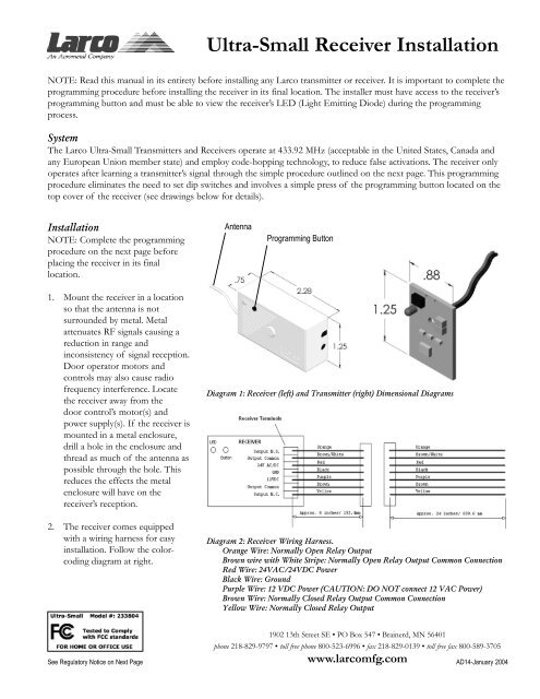
Ultra-Small <strong>Receiver</strong> <strong>Installation</strong>NOTE: Read this manual in its entirety before installing any Larco transmitter or receiver. It is important to complete theprogramming procedure before installing the receiver in its final location. The installer must have access to the receiver’sprogramming button and must be able to view the receiver’s LED (Light Emitting Diode) during the programmingprocess.SystemThe Larco Ultra-Small Transmitters and <strong>Receiver</strong>s operate at 433.92 MHz (acceptable in the United States, Canada andany European Union member state) and employ code-hopping technology, to reduce false activations. The receiver onlyoperates after learning a transmitter’s signal through the simple procedure outlined on the next page. This programmingprocedure eliminates the need to set dip switches and involves a simple press of the programming button located on thetop cover of the receiver (see drawings below for details).<strong>Installation</strong>NOTE: Complete the programmingprocedure on the next page beforeplacing the receiver in its finallocation.AntennaProgramming Button1. Mount the receiver in a locationso that the antenna is notsurrounded by metal. Metalattenuates RF signals causing areduction in range andinconsistency of signal reception.Door operator motors andcontrols may also cause radiofrequency interference. Locatethe receiver away from thedoor control’s motor(s) andpower supply(s). If the receiver ismounted in a metal enclosure,drill a hole in the enclosure andthread as much of the antenna aspossible through the hole. Thisreduces the effects the metalenclosure will have on thereceiver’s reception.2. The receiver comes equippedwith a wiring harness for easyinstallation. Follow the colorcodingdiagram at right.Diagram 1: <strong>Receiver</strong> (left) and Transmitter (right) Dimensional DiagramsDiagram 2: <strong>Receiver</strong> Wiring Harness.Orange Wire: Normally Open Relay OutputBrown wire with White Stripe: Normally Open Relay Output Common ConnectionRed Wire: 24VAC/24VDC PowerBlack Wire: GroundPurple Wire: 12 VDC Power (CAUTION: DO NOT connect 12 VAC Power)Brown Wire: Normally Closed Relay Output Common ConnectionYellow Wire: Normally Closed Relay OutputSee Regulatory Notice on Next Page1902 13th Street SE • PO Box 547 • Brainerd, MN 56401phone 218-829-9797 • toll free phone 800-523-6996 • fax 218-829-0139 • toll free fax 800-589-3705www.larcomfg.com AD14-January 2004
Ultra-Small <strong>Receiver</strong> <strong>Installation</strong>, Cont’dProgramming ProceduresNOTE: Prior to programming, makesure the receiver’s LED blinks redwhen power is applied. If thereceiver’s LED is not blinking red,disconnect then reconnect the power.Programming transmitter(s) intothe receiver’s memory:The receiver can learn up to 12transmitters. Follow the steps belowto program your receiver. Repeatsteps 1-3 for each transmitter.1. Press the receiver’s programmingbutton for less than 2 secondsand release. The LED shouldchange from blinking red to solidgreen, indicating the receiver hasentered its programming mode.2. Activate and release thetransmitter once and confirmthat the receiver’s LED changesto solid red. This indicates thereceiver is learning thetransmitter’s code.3. Wait a few seconds and thenactivate the transmitter a secondtime. The receiver’s LED shouldnow blink green several timesindicating that it is ending itslearning procedure. When theprocedure has ended, the LEDshould be blinking red.Programming the receiver’soutput activation time:When the receiver is activated, itsoutputs will stay in the minimumactivation state for approximately 1.5seconds (default). This time can beadjusted to stay in the activation statefor up to 4 hours. Follow the stepsbelow to adjust the receiver’s outputactivation time.1. Press the receiver’s programmingbutton for 4 seconds and release.The LED should be solid red.This indicates the receiver is inthe activation time programmingmode.2. Activate and release thetransmitter.3. When the desired time haselapsed (up to 4 hours) activatethe transmitter again. Thereceiver’s LED should blinkgreen several times indicating it isending the procedure. When theprocedure has ended, the LEDshould be blinking red.SpecificationsTransmitterFrequency:433.92 MHzDimensions:1.25” x 0.875” x 0.25”Security Code Method:Code HoppingBattery Life:60,000 cyclesCertifications:FCC, Industry Canada, CEOperating Temperature Range:-4 o F to 122 o F (-20 o C to 55 o C)<strong>Receiver</strong>Frequency:433.92 MHzDeleting all transmitters from thereceiver’s memory:You can clear the receiver’s memoryof all previously learned transmittersby following the steps below. NOTE:Deleting previously learnedtransmitters does not change thereceiver’s output activation time.1. Press the receiver’s programmingbutton for more than 8 secondsuntil the receiver’s LED startsblinking green. Releasethe programming button. TheLED should now be blinking red.2. The receiver’s memory is nowcleared. To learn newtransmitters, follow the steps forprogramming transmitters intothe receiver’s memory.Dimensions:2.25” x 1.25” x 0.75”Security Code MethodCode HoppingCan learn up to 12 differenttransmittersOperating Temperature Range:-4 o F to 122 o F (-20 o C to 55 o C)Electrical Rating:100,000 cycles at 2 Amps at either24 VDC or 120 VACInput Power:24 VAC, 24VDC or 12 VDCOutput:Two Relay Outputs: 1 NO 1 NCCertifications:FCC, Industry Canada, CEThe receiver and transmitter comply with FCC part 15/15.231-2001, Industry Canada RSS-210-2003, EN55022A-2000, EN55024-2001, EN300-220-3 V1.1.1-2000, and EN301-489-1V1.2.1-2000. Operation is subject to the following two conditions: (1) This device may not cause harmful interference, and (2) this device must accept any inerference received,including interference that may cause undesired operation. This product may be susceptible to local transmissions being generated near the transmitter’s fundamental frequency.Testing has shown some susceptibility in a frequency range of 416-440 MHz.NOTE: This equipment has been tested and found to comply with the limits for a Class B digital device, pursuant to part 15 of the FCC rules. These limits are designed to providereasonable protection against harmful interference in a residential installation. This equipment generates, uses and can radiate radio frequency energy and, if not installed and used inaccordance with the instructions, may cause harmful interference to radio communications. However, there is no guarantee that interference will not occur in a particular installation. Ifthis equipment does cause harmful interference to radio or television reception, which can be determined by turning the equipment off and on, the user is encouraged to try to correctinterference by one or more of the following measures: (a) Reorient or relocate the receiving antenna. (b) Increase the separation between the equipment and receiver. (c) Connect theequipment into an outlet on a circuit different from that to which the receiver is connected (d) Consult the dealer or an experienced radio/TV technician for help.The user is cautioned that any internal modifications, either replacement of or modification of any component, of the transmitter or receiver could violate the rules of compliance andauthority to operate the equipment.