HR94D-C1 Installation Guide - Hotron
HR94D-C1 Installation Guide - Hotron
HR94D-C1 Installation Guide - Hotron

You also want an ePaper? Increase the reach of your titles
YUMPU automatically turns print PDFs into web optimized ePapers that Google loves.
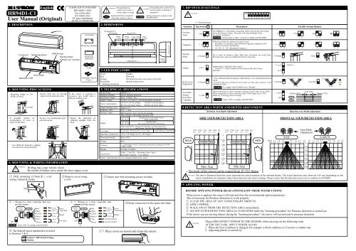
English<strong>HR94D</strong>1-<strong>C1</strong>User Manual (Original)1. DESCRIPTIONCOMPLIED STANDARDSDIN18650-1:2005EN 12978:2003EN 16005:2012EC type examination44 205 12 414283-001!NoteWARNING Disregarding thissymbol may result inserious injury or deathSpecial attention is requiredwhen this symbol is shown2. DIMENSIONS!EN16005Disregarding this symbol mayCAUTIONresult in injury or damage toequipmentSetting required to conform withEN16005:20127. DIP SWITCH SETTINGS!CAUTION☆ = Default SettingFunction Dip Switch XONDescription1 2 3 4 5 6 7 8Possible Setting OptionsConnectorMounting HolesCoverDIP SwitchPotentiometer(Sensitivity Volume)AccessoriesMounting Template<strong>Installation</strong>InstructionΦ10mm(0.39")-Wiring hole35mm(1.38")75mm(2.96")40mm(1.57")15mm 20mm(0.59") (0.79")210mm(8.27" )5mm(0.20")30mm(1.18")65mm(2.56")PresenceTimerFrequencyMonitorMode☆30s☆ ANormal ☆1 23 45The <strong>HR94D</strong>1-<strong>C1</strong> will detect a stationary object only for the time periodset by the Presence Timer. The timer will reset and begin if anymovement is detected.EN16005 Set the timer to 30sec. or more to comply with EN16005When more than two sensors are used in closeproximity to each other, select different frequency setting for eachsensors to prevent interference.( A + B + C + D = Maximum 4 sensors )Set to snow in instances where false door activations can result fromblowing snow, leaves or rubbish in the door close area.2s1 2☆ A3 4☆ Normal5☆30s60s1 21 2BC∞1 2D3 4 3 4 3 4Snow54. MOUNTING PRECAUTIONSMounting height of 3 m(9.8ft) or lower6. MOUNTING & WIRING INFORMATION1 Drill mounting (3.5mm φ ) a n dwiring (10mmφ) holes.Sensor’sCable3m (9.8ft)If possible ensure noaccumulation of snow orwater on the floor.Use different frequency settingsfor sensors in close proximity!Area MaskIndicator LEDWARNING50mmCableRedBlackYellowAC/DC Power12 to 24 [V]±10% (Non Pole)CollectorEmitterTest-PTest-N2 Remove cover usinga coin.OutputTest InputCableMounting Screws(2 pcs.)Drilling may cause electric shock.Be careful of hidden wires inside the door engine cover.4-1 Wiring to a door controller that cantest the sensor.Blue(-)GrayON8BrownEN16005 Set to “ON” to comply with EN16005Ensure there are no movingobjects in the detection zoneEnsure no condensation getsonto the sensor.6 Set desired sensor parameters as notedin Sections 7 & 8.ASection 7. DIP Switch SettingsSection 8. Detection Area Width andDepth AdjustmentBIf the sensor is exposed toexcessive rain install with a<strong>Hotron</strong> weather coverEnsure the minimum ofreflected sunlight from thefloor3. LED INDICATORSGreenRedOrangeGreen/Redblinking alternatelyStandbyDetectingThe detection area is too close to the doorInternal Sensor Error5. TECHNICAL SPECIFICATIONSModel NameDetection Method<strong>Installation</strong> HeightSupply VoltagePower ConsumptionOutput Holding TimeResponse TimePresence TimerOutputTest InputOperating TemperatureOperating humidityIP RateCategoryWeightAccessories4 -2 Wiring to a door controller thatcannot test the sensor.Sensor’sCableOFF8CableRedBlackYellowBlue(-)GrayBrown<strong>HR94D</strong>1-<strong>C1</strong>Active Infrared Detection3[m] (9.8[ft]) MaxAC/DC 12 to 24 [V] ±10% Red & Black (Nonpole)A<strong>C1</strong>2V-1.8 [VA] (Max) AC24V-2.8 [VA] (Max)D<strong>C1</strong>2V-100 [mA] (Max) DC24V-60 [mA] (Max)Approx 0.5s0.1s ~ 0.2sDIP Switch #1, #2 (2, 30, 60, ∞ seconds)Open collector 7.5[mA](Max) Resistor LoadDIP SWNormally Drive (Normally Close)#6 : N.C.Open on DetectionDIP SWNormally Open#6 : N.O.Drive on Detection (Close on Detection)Opto coupler(NPN) Voltage:55 [VDC] Max. Current:50 [mA] Max.Dark Current : 100 [nA] Max. (Resistance load)Non-Test : D<strong>C1</strong>2 to 24 V / Test : Open 6 [mA] Max.@ 24 [VDC]-20 to +60 [Deg.C],(-4 to 140 Deg.F)Below 80%IP542 , performance level C for presence detection according to EN ISO13849-1:20080.190kg, ( 0.42lbs.)Cable : 2.5m (8ft.) Mounting Screw (2pcs)Mounting Template User ManualNotice: Specification may be changed without prior notice.3 Fasten unit with mounting screws rovided.AC/DC Power12 to 24 [V]±10% (Non Pole)CollectorEmitterdo not connectdo not connectOutput5House connectors in the space provided.7 7. Place cover on sensor and clean the sensor.OutputReflectionDiagnosticsTest InputSettingfrom DoorController☆N.C.6Output logic is defined by this switch.In the N.C. , Opto-Coupler will be driven in the state of nondetection.8.DETECTION AREA WIDTH AND DEPTH ADJUSTMENTMAX!Detection Area Depth AdjustmentSIDE VIEW/DETECTION AREA2.5m 2.0m 1.5m 1.0m 0.5m 0m 2.5m 2.0m 1.5m 1.0m 0.5m 0m8.2' 6.6' 4.9' 3.3' 1.6' 0' 8.2' 6.6' 4.9' 3.3' 1.6' 0'Max AreaMin Area» The body of the sensor can be rotated from 0º~5º(3 Steps)9. APPLYING POWER!CAUTION☆ Normal☆ OFF78[ 5 degree ] settingA low reflected infrared signal is indicated by a slow flashing Red/GreenLED.To ignore this low reflection error state, set this dip switch to “LowReflection”(ON).EN16005To comply with EN16005 set to “Normal”When connected to a door controller without a TEST input, set to “OFF”.When connected to a door controller with a TEST input, set to “ON”Refer to [11.Timing Chart of events].EN1600500.5m1.6'1.0m3.3'1.5m4.9'2.0m6.6'2.5m8.2'3.0m9.9'Set to “ON” to comply with EN16005[ 0 degree ] settingMIN☆ N.C.BEFORE APPLYING POWER, READ AND FOLLOW THESE INSTRUCTIONS:N.O.☆ Normal☆ OFF7Detection Area Width AdjustmentFRONTAL VIEW/DETECTION AREAWIDEArea MaskAdjustment(m) 2.0 1.5 1.0 0.5 0.5 1.0 1.5 2.06.6' 4.9' 3.3' 1.6' 1.6' 3.3' 4.9' 6.6'00.5m1.6'1.0m3.3'1.5m4.9'2.0m6.6'2.5m8.2'3.0m9.9'NARROW2.0 1.5 1.0 0.5 0.5 1.0 1.5 2.06.6' 4.9' 3.3' 1.6' 1.6' 3.3' 4.9' 6.6'When power is applied, the sensor will read and store the environmental optical parameters.This is necessary for Presence Detection to work properly.1 CLEAR THE AREA OF ANY UNNECESSARY OBJECTS.2 APPLY POWER.3 WALK AWAY FROM THE DETECTION AREA immediately.4 DO NOT ENTER DETECTION AREA for 10 SECONDS while the “learning procedure” for Presence detection is carried out.If the sensor can see moving objects during the "learning procedure", the sensor will not proceed to presence detection.(Drive)Please DISCONNECT POWER TO THE SENSOR, when carrying out the following work.AFTER THE TASK, APPLY POWER AGAIN.1. When the floor condition is changed; for example with the addition of of woolen or rubber mat.2. Adjusting pattern or sensitivity.ON678TransmitterIR SpotOFF 0vONReceiverWithout TEST0vLow Ref.With TEST7TransmitterWithout TESTCAUTION The above illustrated detection areas represent the actual position of the infrared beams. The actual detection area observed will vary depending on thesensor installation environment, object been detected and sensor settings. Please ensure that the detection area is set to conform to EN16005.IR SpotReceiverLED
10. VERIFICATION OF OPERATION 13. TROUBLESHOOTING1. After mounting, setting parameters and applying power, walk test unit toSensitivityverify detection area.Sensor does notoperate2. If the door does not operate properly, recheck the dip switch settings andpattern adjustments.HighSensor intermittently detects3. After rechecking, if there is still a problem, adjust the sensitivity.» Adjust high (clockwise) to increase sensitivity.» Adjust low (counter-clockwise) to decrease sensitivity.!CAUTIONAs the detection area is variable depending on clothes, floor material and sensitivity adjustment,please confirm that the detection area demanded in EN16005 is secured after adjustment.11. TIMING CHART OF EVENTSProblems Possible Cause SolutionSensor ConnectorTighten connector or reconnectSensor detects withoutobvious reasonThe door kept open,although there isno object in the detection area.Power SupplySensor is very dusty orcovered in water drops, etc.Sensitivity too lowDetection pattern in the wrong positionSensitivity too highAnother sensor is too close bySensor detects the door movementThere is a cloth mat in the monitored area.Detection pattern too far in front of the door, detectingpeople passing byThe condition of the monitored area isvarying.・Dusty / Dirty・SnowInternal error(Green/Red LED blinks alternately)Check that the power supply is properly connected.Clean the sensor (do not use thinner or alcohol to clean sensor)Turn up sensitivityAlter the detection pattern by changing sensor angle, and/or pattern width adjustmentsTurn down Sensitivity.Change the frequency to each sensor.If the indicator LED is an Orange color, adjust the pattern depth angle away from the doorReactivate the sensor and wait for 10 seconds.Adjust the detection pattern - move it closer to the doorThe condition of the monitored area can change due to heavy dust or dirty,heavy snow orfootprints being left in fresh snow, this will cause the malfunction sometimes. Set the “Presence Timer” toa short times.Refer to Section 7.Fast blink Please replace the sensor (Refer to Section 12)Slow blinkLow reflection error or Test line disconnection(Refer to Section 7, Section 12)Dip Switch#6:N.C.Dip Switch#6:N.O.POWEROFFYellowBlueYellowBlue12. SELF DIAGNOSTICS ERRORSNON-DETECTIONTest InputYellowBlueYellowBlueGrayDETECTIONNON-TESTSensorYellowBlueYellowBlueBrownSupplying D<strong>C1</strong>2 to 24V, make current flowfrom Gray to Brown.NON-DETECTIONYellowBlueYellowBlueT1GrayTESTDETECTION asresponse to TESTSensorBrownBreak the currentflow on test state.T1: 8~14[mSec] App.When the sensor has the self-test error, the green/red LED blinks alternately.The blinking cycle is different, according to the kinds of the error as follows.YellowBlueYellowBlueTEST RESPONSET2BrownNON-DETECTIONGrayNON-TESTSensorT2: 9~15 [mSec]App.YellowBlueYellowBlue14. <strong>HR94D</strong>1-<strong>C1</strong> EC DECLARATION OF CONFORMITYCompiler of Technical File (EC Community)David Morgan<strong>Hotron</strong> Ireland Ltd26 Dublin Street, Carlow, IrelandPh: +353-(0)59-9140345 Fax: +353-(0)59-9140543Above EC Type Directives Certified by:TUV NORD CERT GmbH30519 Hannover, GermanyIdentification No: 0044Description of Product:<strong>HR94D</strong>1-<strong>C1</strong> is designed to monitor the side screen of the automatic door.Technology used is Active Infrared TechnologyHarmonized Standards Used:EN ISO 13849-1:2008Declaration made byKaoru MusyaGeneral Manager. Honda ElectronOther Technical Standards Used:DIN 18650-1:2005,EN16005:2012Location of DeclarationHonda Electron Co., LTD.1-23-19 Asahi-Cho, Machida-City,Tokyo, JapanDirectives Fulfilled:DIRECTIVE 2006/42/ECDIN 18650-1:2005 Powered pedestrian doors Part 1: Product requirements chapter 5.7.4EN12978:2003 Industrial, commercial and garage doors and gates - safety devices for power operated doors and gates - Requirements and test methods.EN62061:2005 Functional safety of electrical/electronic/programmable electronic safety-related systems.EN ISO 13849-1:2008 Safety of machinery - Safety-related parts of control systems.EN 16005:2012EC type examination 44 205 12 414283-001Date9 th of Nov 2012< Disclaimer > The manufacturer cannot be held responsible for below.1. Misinterpretation of the installation instructions, miss connection, negligence, sensor modification and inappropriate installation.2. Damage caused by inappropriate transportation.3. Accidents or damages caused by fire, pollution, abnormal voltage, earthquake, thunderstorm, wind, floods and other acts of providence.4. Losses of business profits, business interruptions, business information losses and other financial losses caused by using the sensor or malfunction of the sensor.5. Amount of compensation beyond selling price in all cases.■Fast Blink ( Green/Red )GreenRed■Slow Blink ( Green/Red )GreenRedLED Cause Solution Response to TEST Output on Error State■Slow Blink ( Red/Red/Green )GreenRedInternal errorLow reflectionlevelTest linedisconnectionPlease replace the sensor.Set the sensitivity to maximum,and then reactivate the sensor.If the error continues, setDIP Switch #7 “ON” .Please confirm the connectionof the test line.No ResponseDIPSwitch#6 : N.O.DIPSwitch#6 : N.C.YellowBlueYellowBlueRManufacturerHOTRON CO.,LTD.1-11-26 Hyakunin-Cho, Shinjuku-Ku, Tokyo, JapanPhone: +81-(0)3-5330-9221Fax: +81-(0)3-5330-9222URL: http://www.hotron.comSALES Europe<strong>Hotron</strong> Ireland Ltd.26 Dublin Street (2nd Floor), Carlow, IrelandPhone: +353-(0)59-9140345Fax: +353-(0)59-9140543URL: http://www.hotron.comMP-10139 '13.01PRINTED IN JAPAN