SSR-3 User Manual (Original) ! ! ! ! ! ! - Hotron
SSR-3 User Manual (Original) ! ! ! ! ! ! - Hotron
SSR-3 User Manual (Original) ! ! ! ! ! ! - Hotron

You also want an ePaper? Increase the reach of your titles
YUMPU automatically turns print PDFs into web optimized ePapers that Google loves.
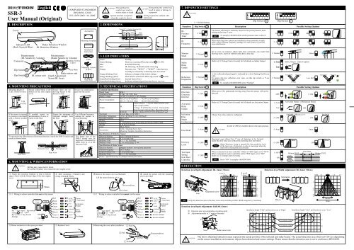
English<strong>SSR</strong>-3<strong>User</strong> <strong>Manual</strong> (<strong>Original</strong>)1. DESCRIPTIONCoverIndicator LED(Red, Green & Blue)Potentiometer(IR. Sensitivity Volume)ConnectorDip Switch XDip Switch Y4. MOUNTING PRECAUTIONSMounting height of3.2m (10.5ft) or lower3.2m(10.5ft)If the sensor is exposedto excessive rain installwith a <strong>Hotron</strong> weathercoverMount within 50mm of thebottom of the door enginecoverIf possible ensure noaccumulation of snow orwater on the floor.6. MOUNTING & WIRING INFORMATION!AWARNINGBSide ViewDrilling may cause electric shock.Be careful of hidden wires inside the door engine cover.1 Attach the mounting template so that its bottomedge is flush with the bottom edge of the door enginecover.Radar Detection WindowIR. Detection WindowIR. sensor unitMax 50mmPotentiometer(Radar Sensitivity Volume)Mounting Screws(2 pcs.)Radar sensor unitDepth AdjustmentScrew(IR. Area)Ensure there are nomoving objects in thedetection zoneEnsure the minimum ofreflected sunlight fromthe floorTo maximize the effectiveness of doorway detection, install the <strong>SSR</strong>-3 outside andinside as shown below.Moving Door LeafABPlan ViewMoving Door LeafCOMPLIED STANDARDSDIN18650-1:2010EN 12978:2003 +A1:2009Area Mask2 Drill mounting (3.5mmφ) andwiring (10mmφ) holes.AccessoriesMounting TemplateAInstallationInstructionCableMounting Screws(2 pcs.)Area MaskEnsure no condensationgets onto the sensor.Use different frequencysettings for sensors inclose proximityThe Radar part of the<strong>SSR</strong>-3 sensor may benegatively influenced bymetal close to or in thedetection fieldB!NoteWARNING Disregarding thissymbol may result inserious injury or deathSpecial attention is requiredwhen this symbol is shown2. DIMENSIONS3. LED INDICATORSGreenGreen blinkingBlueRedOrangeOrange blinking (Fast)Orange blinking (Slow)Green/Red blinking (Fast)Green/Red blinking (Slow)!DIN75mm(2.95") = Standard Mounting Pitch25mm(0.98") (0.59")15mm 35mm(1.37")10mm(0.39")Disregarding this symbol mayCAUTIONresult in injury or damage toequipmentSetting required to conform withDIN18650265mm (10.43") 43mm (1.69")StandbyDoorway Learning (When dip switch Y 5 is ON)RADAR DetectingIR. Detecting / RADAR and IR. DetectingDetection row “ROW1”(“ROW2” when doorwayLearning is turned ON) is detecting door movementIndicates a change of dip switch settingsDoor Hold is turned ON (When dip switch Y 4 is ON)Internal Sensor ErrorReflected infrared signal from the floor is very low5. TECHNICAL SPECIFICATIONSCommon SpecificationModel Name<strong>SSR</strong>-3Installation Height 3.2[m] (10.5 [ft]) MaxSupply VoltageAC/DC 12 to 24 [V] ±10% 50/60HzPower ConsumptionAC12V-2.5 [VA] (Max) AC24V-2.5 [VA] (Max)DC12V-150 [mA] (Max) DC24V-80 [mA] (Max)Open collector: 7.5 [mA] (Max) Resistor LoadOutputIR.Opto coupler (NPN)Voltage: 55 [VDC] Max. Current : 50 [mA] Max.Dark Current: 100 [nA] Max. (Resistance load)RADAR Form A Relay DC50 [V] 0.1[A] Resistor LoadTest Input6 [mA] Max. @ 24 [VDC]Operating TemperatureOperating humidity-20 to +60 [Deg.C],(-4 to 140 Deg.F)Below 80%IP RateIP54Category 2 , performance level D according to EN ISO 13849-1:2008WeightColor0.56 [lb.] (0.26 [kg])Black, SilverAccessoriesCable , Mounting Screw 2pcs.,Mounting Template, Installation InstructionSpecifications of Reflection SensorDetection Method Active Infrared ReflectiveOutput Holding Time 0.5 [seconds] App.Response Time0.1 ~ 0.2 [seconds]Presence Timer2, 30, 60 [seconds] or ∞Specifications of Redar SensorDetection Method Doppler method: ( moving body detection)Transmit frequency 24.15 [GHz]Output Holding Time 1.5 [seconds] App.Response Time0.1 ~ 0.2 [seconds]Notice: Specification may be changed without prior notice.3 Remove the sensor cover as illustratedLift the sensor from its cover60mm (2.36")4 Attach the sensor with the mountingscrews provided7. DIP SWITCH SETTINGS!FunctionIR.PresenceTimerIR.FrequencyMonitorModeSafetyRelayOutputReflectionDiagnosticsFunctionDirectionDetectionRADARActivationRelayOutputDoor HoldDoorwayLearnTest InputSettingfrom DoorControllerCAUTIONActivationRelayOutputConfiguration☆ = Default SettingDip Switch X☆30s☆ A☆ Normal☆ N.O.☆ Normal☆ ON☆ OFF☆ OFF1 23 4567Dip Switch Y☆ N.O.☆ OFF☆ Auto123456Description1 2 3 4 5 6 7Dip Switch XThe sensor will detect a stationary object for the preset presence timersetting on the inner 3 rows.DINWhen more than two sensors are installed in close proximity to eachother select different frequency settings for each sensor to preventcross interference.Set to snow in instances where false door activations can result fromblowing snow, leaves or rubbish in the door close area.Refer to [11.Timing Chart of events] for full details on Safety OutputWhen set to ON, pedestrians moving away from the sensor will not bedetected.Doorway Learn allows the 1 st row of detection to be focusedinside the door close area without the detecting door movement.NoteTo comply with DIN18650 set the presence timer to 60s ormoreA low reflected infrared signal is indicated by a slow flashing Red/GreenLED.To ignore this low reflection error state, set this dip switch to “LowReflection”(ON).DIN!DescriptionWhen Doorway Learn is turned ON, the sensitivity levelof the inner row of detection is only at maximum when theouter rows of detection are activatedWhen connected to a door controller without a TEST input, set to “OFF”.When connected to a door controller with a TEST input, set to “ON”Refer to [11.Timing Chart of events].DINTo comply with DIN18650 set to “Normal”Refer to [11.Timing Chart of events] for full details on Activation OutputChoose how relay output is configured.CAUTIONSwitch to OPEN to hold the door in the open positionSet to “ON” to comply with DIN186508.DETECTION AREA WIDTH AND DEPTH ADJUSTMENTDetection Area Depth Adjustment: IR. (Inner 3 Rows)【 Far 】1.0[m][4 degree] setting0.50ON【 Near 】1.0 [m] 0.5[-8 degree] setting02s☆ A☆ Normal☆ OFF1 23 4☆N.O.N.C.☆ NormalOFF☆ Auto1 2 3 4 5 6Dip Switch YON☆ N.O.N.C.☆ OFF☆ OFFON5671234☆30sBDoorPossible Setting Options60s1 2 1 2 1 2CON∞3 4 3 4 3 4Safety Output (Opto-Coupler)TransmitterIR SpotReceiverPossible Setting Options☆ ON5 56Without TESTOFF 0vON0vSnowLow Ref.Activation Output (Mechanical Relay)OpenWith TESTDetection Area Width Adjustment: IR. (Inner 3 Rows)SeparationORRADAR + IR rows 2+3ON57134DTransmitterWithout TEST2.0[m]1.0IR SpotRADARDoor0ReceiverLED1.0 2.0NoteSet “Test input” dip switchsetting Y 6 to “ON”Ref section 7, Dip SwitchSettings.Sensor’sCableON 650mmCableRedBlackWhiteGreenYellow(+)Gray(+)50mm5-1 Wiring to a door controller that can test the sensor 5-2 Wiring to a door controller that cannot test the sensorDINOFFYBlue(-)Brown(-)AC/DC Power12 to 24 [V]±10% (Non Pole)N.O.COMCollectorEmitterTest-PTest-NActivationOutputSafetyOutputTest InputNoteSet “Test input” dip switchsetting Y 6 to “OFF”Ref section 7, Dip SwitchSettings.Flat screwdriverSlit in baseSensor’sCableOFFON 6CableYRedBlackWhiteGreenYellow(+)Blue(-)Gray(+)Brown(-)AC/DC Power12 to 24 [V]±10% (Non Pole)N.O.COMCollectorEmitterActivationOutputSafetyOutputdo not connectdo not connectDINFarNearAdjustment screwDetection Area Depth Adjustment: RADAR (Outer)Far1.0Door 2.02.2Verify the detection area in the door close area according to DIN 18650 using the CA test body※ Detection area varies depending on walking speed※ Adjustment possible in 3 ° steps as illustrated3.03.2Door1.02.02.23.03.2Put onInstallation height "2.2m" and Sensitivity set to "High".1.02.0 [m] 1.0 0 1.0 2.0[15 degree] setting1.02.02.23.03.2NarrowWideInstallation height "2.2m" and Sensitivity set to "Low".2.0 [m] 1.0 0 1.0 2.01.06 House connectors in the space provided.7 Replace Cover.※Removing the cover after installation1 Push2.0[30 degree] setting2.02 Pull1 Push2 PullFlat screwdriver!CAUTIONNearRadar sensor unit3.0[45 degree] settingThe above illustrated detection areas represent the actual position of the infrared and radar beams. The actual detection area observed will vary dependingon the sensor installation environment, objects been detected and sensor settings. Please ensure that the detection area is set to conform to DIN18650.3.0
9. APPLYING POWER AND THE “DOORWAY LEARN” SETTING12. DOOR MAINTENANCE WORK13. SELF DIAGNOSTICS ERRORS“Doorway Learn” is OFFRef section 7, Dip Switch Settings.Upon power ON, the solid green LED turns on indicatingthat the sensor is in standby mode and ready to detectGreen solid LEDY5“Doorway Learn” is ONRef section 7, Dip Switch Settings.Upon power ON, the Red LEDindicates a door open relay outputto begin the doorway learn processY 5Green LED blinks for 37s as the “door learn” process is carriedout. Door opens/closesRed solid LED Green blinking LED Green blinking LEDDoor learn process complete,sensor in standby modeGreen solid LEDWhen carrying out door maintenance work with power applied to thesensor on door controllers that are wired to “test” the sensor ensure toset the dip switches as below.Note remember to return the dip switch settings to their originalstate once door maintenance work has been carried out.ONDip SwitchX1 2 3 4 5 6 7Technical problems with the S S R - 3 sensor are indicated by a flashing Green/Red LED. The frequency offlashing indicates the type of problem as explained belowFlashFrequencyFastGreenRedLEDCausePlease replace the sensor.2s1 2LowRef. 7Refer to [7.Dip Switch Settings].SlowGreenRedConfirm that the sensitivity potentiometer is set tomaximum and re-power the sensor.If the error persists, setDip Switch X 7 to “Low Reflection”.Presence Detection: It takes 10s after sensor power upfor presence detection to be initiated on all rows ofdetection.If before 10s has elapsed someone walks into the detectionarea it will take about 5s after the person leaves thedetection zone for presence detection to be functional.10. VERIFICATION OF OPERATION11. TIMING CHART OF EVENTS!NoteCAUTIONAfter installation is completed “walk test” the sensor detection area. If the detection area is not as expected adjust thedetection area as referred to in section 8If the detection area is still not as expected then the sensor sensitivity can be increased by turning the potentiometerclockwise. When the sensor detects even though there is nothing in the detection area the sensor sensitivity can bedecreased by turning the potentiometer in the anti-clockwise direction.Safety Output / Test InputActivation OutputDip Switch XSafety OutputDip Switch YN.O.N.C.Test Input setting63 2 1POWER OFFOFFONYellowBlueYellowBlue6T1 : 10±1 [mSec] AppT2 : 11±1 [mSec] AppPresence Detection: During the “Doorway Learn” process the outer 3 rows of detection on the <strong>SSR</strong>-3 sensor switchfrom motion detection to presence detection 10s after power ON. The inner “door learn” row of detection will switchfrom motion to presence detection after the “doorway learn” process is carried out.When Doorway Learn is turned ON, the sensitivity level of the inner row of detection is only at maximum when the outerrows of detection are activatedNON-DETECTIONTest Input“Doorway Learn” Failure & Recovery: If a person enters the detection area during the “doorway learn” process itmay not be successfully completed. In this case the sensor will carry out the doorway learn process over three dooractivations by a person in order to build an accurate image of the door open and door close position.YellowBlueYellowBlueGrayDETECTIONTESTNON-TESTSensorYellowBlueYellowBlueBrownSupplying DC12 to 24V, make current flow fromGray to Brown.Dip Switch3 21Y -3 ON3 213 21YellowBlueYellowBlueT1IR. SensitivityGrayHNON-TESTTESTLNON-DETECTIONYellowBlueYellowBlueTEST RESPONSESensorBrownBreak the currentflow on test state.Dip SwitchRADAR SensitivityT2HY -3 OFF3 2LDETECTION asresponse to TESTTESTNON-TESTGrayBrown1YellowBlueYellowBlueSensor14. TROUBLESHOOTINGProblemDoor does not open when aperson enters the detectionareaDoor opens and closes for noapparent reason (Ghosting)When Door opens or closes,LED ORANGEDoor opens and remains in theopen position15. <strong>SSR</strong>-3 EC DECLARATION OF CONFORMITYWe <strong>Hotron</strong> declare that this sensor complies with all of the applicable EHSRs of Annex I of the Machinery Directive and that the appropriate conformity assessment procedure has beencarried out.We, the manufacturer (Honda Electron Co., LTD.) hereby declare that this equipment (Combined Technology Sensor), model <strong>SSR</strong>-3 is in compliance with the essentialrequirements and other relevant provisions of Directive R&TTE 1999/5/ECCompiler of Technical File (EC Community)David Morgan<strong>Hotron</strong> Ireland Ltd26 Dublin Street, Carlow, IrelandPh: +353-(0)59-9140345 Fax: +353-(0)59-9140543LED Status Possible Cause SolutionOFFDoor OpensRED or BLUEDoor ClosesGREENORANGEREDGREEN/REDFAST FLASHGREEN/REDSLOW FLASHORANGE blinking(Slow)EC-type examination No. 44 205 401191-000Certified by: Mo. 0044 TÜV NORD CERT GmbH,Langemarckstr. 20,45141 Essen,GermanySensor Connector not connected correctlyIncorrect power supply voltageIncorrect sensor wiringObject moving in the detection areaSensitivity too high for the installation environmentDust, frost or water droplet on the sensor lensDetection area overlaps with that of another sensorDetection of falling snow, insects, leaves etcDetection row “ROW1” (“ROW2” when “DoorwayLearn” is turned ON) is focused too close to the door.Detection area changed, while ∞ infinitypresence timer setting is in useIncorrect sensor wiringReflected signal saturationInternal sensor errorReflection of the transmitted infrared signal fromthe floor is too lowDoor Hold (Dip switchY 4 set to Open)Description of Product:<strong>SSR</strong>-3 Combined motion and presence detection sensor for the activation and safety of automatic doors.Technology used is Active Infrared Technology and Doppler method: ( moving body detection) TechnologyHarmonized Standards Used:EN ISO 13849-1:2008Declaration made byReiji KuwashimaQuality Assurance Manager. HondaElectronTighten or reconnect the connector.Apply proper voltage to the sensor. (AC/DC 12-24V)Double check sensor wiringRemove the moving object from detection area.Reduce the sensor sensitivity settingWipe the sensor lens clean and install a weather cover if necessaryEnsure different frequency setting for each sensor, and adjust to overlap theradar area using the angle and volume.Turn monitor mode Dip switch X 5 to “snow”Adjust detection depth for Inner 3 rows away from the door.Re-power the sensor or change the presence timer settings to 30 or 60 secsDouble check sensor wiringRemove highly reflective objects from the detectionarea, or lower the sensor sensitivity settingBLUE Moving objects in the radar area Eliminate moving objectsReplace the sensorIncrease sensor sensitivity or change the “Reflection Diagnostics”Dip switch X 7 from “Normal” to “Low Ref”Turn “Door Hold” Dip switchOther Technical Standards Used:DIN 18650-1:2010Y 4 to AutoLocation of DeclarationHonda Electron Co., LTD.1-23-19 Asahi-Cho, Machida-City,Tokyo, JapanDate31th of August 2011Directives Fulfilled:DIRECTIVE 2006/42/ECDIN 18650-1:2010 Powered pedestrian doors Part 1: Product requirements chapter 5.7.4EN12978:2003 +A1:2009 Industrial, commercial and garage doors and gates - safety devices for power operated doors and gates - Requirements and test methodsEN62061:2005 Functional safety of electrical/electronic/programmable electronic safety-related systemsEN ISO 13849-1:2008 Safety of machinery - Safety-related parts of control systems.< Disclaimer > The manufacturer cannot be held responsible for below.1. Misinterpretation of the installation instructions, miss connection, negligence, sensor modification and inappropriate installation.2. Damage caused by inappropriate transportation.3. Accidents or damages caused by fire, pollution, abnormal voltage, earthquake, thunderstorm, wind, floods and other acts of providence.4. Losses of business profits, business interruptions, business information losses and other financial losses caused by using the sensor or malfunction of the sensor.5. Amount of compensation beyond selling price in all cases.Dip Switch YActivation OutputPOWER OFFNON-DETECTIONDETECTION3 2 13 2 13 2 1POWER OFF NON-DETECTION DETECTIONRN.O.N.C.2GreenWhiteGreenWhiteGreenWhiteGreenWhiteGreenWhiteGreenWhiteGreenWhiteGreenWhiteGreenWhiteGreenWhiteGreenWhiteGreenWhiteManufacturerHOTRON CO.,LTD.1-11-26 Hyakunin-Cho, Shinjuku-Ku, Tokyo, JapanPhone: +81-(0)3-5330-9221Fax: +81-(0)3-5330-9222URL: http://www.hotron.comSALES Europe<strong>Hotron</strong> Ireland Ltd.26 Dublin Street (2nd Floor), Carlow, IrelandPhone: +353-(0)59-9140345Fax: +353-(0)59-9140543URL: http://www.hotron.comMP-10086-C '12.01PRINTED IN JAPAN