
Create successful ePaper yourself
Turn your PDF publications into a flip-book with our unique Google optimized e-Paper software.
®<br />
<strong>6th</strong> <strong>Ed</strong>. Associate CET Study<br />
Guide <strong>Errata</strong> <strong>Sheet</strong><br />
An updated version of the Associate CET Study Guide <strong>Errata</strong> <strong>Sheet</strong><br />
can be found online at www.eta-i.org/<strong>6th</strong><strong>Ed</strong><strong>AST</strong><strong>Errata</strong><strong>Sheet</strong>.pdf<br />
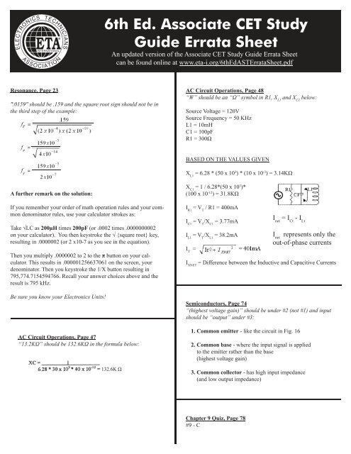
Resonance, Page 23<br />
".0159" should be .159 and the square root sign should not be in<br />
the third step of the example:<br />
AC Circuit Operations, Page 48<br />
“W” should be an “Ω” symbol in R1, X L1<br />
and X C1<br />
below:<br />
Source Voltage = 120V<br />
Source Frequency = 50 KHz<br />
L1 = 10mH<br />
C1 = 100pF<br />
R1 = 300Ω<br />
BASED ON THE VALUES GIVEN<br />
X L1<br />
= 6.28 * (50 x 10 3 ) * (10 x 10 -3 ) = 3.14KΩ<br />
A further remark on the solution:<br />
If you remember your order of math operation rules and your common<br />
denominator rules, use your calculator strokes as:<br />
Take √LC as 200μH times 200pF (or .0002 times .0000000002<br />
on your calculator). You then keystroke the √ {square root} key,<br />
resulting in .0000002 (or 2 x10⁻⁷ as you see in the equation).<br />
Then you multiply .0000002 to 2 to the π button on your calculator.<br />
This results in .000001256637061 on the screen, your<br />
denominator. Then you keystroke the 1/X button resulting in<br />
795,774.7154594766. Recall your answer choices above and the<br />
result is 795 kHz.<br />
X C1<br />
= 1 / 6.28*(50 x 10 3 )*<br />
(100 x 10 -12 ) = 31.8KΩ<br />
I R1<br />
= V T<br />
/ R1 = 400mA<br />
I C1<br />
= V T<br />
/X C1<br />
= 3.77mA<br />
I L1<br />
= V T<br />
/X L1<br />
= 38.2mA<br />
I T<br />
=<br />
I net<br />
= I Ct<br />
- I Lt<br />
I net<br />
represents only the<br />
out-of-phase currents<br />
I XNET<br />
= Difference between the Inductive and Capacitive Currents<br />
Be sure you know your Electronics Units!<br />
Ω<br />
Semiconductors, Page 74<br />
“(highest voltage gain)” should be under #2 (not #1) and input<br />
should be “output” under #3:<br />
AC Circuit Operations, Page 47<br />
“13.2KΩ” should be 132.6KΩ in the formula below:<br />
132.6K Ω<br />
1. Common emitter - like the circuit in Fig. 16<br />
2. Common base - where the input signal is applied<br />
to the emitter rather than the base<br />
(highest voltage gain)<br />
3. Common collector - has high input impedance<br />
(and low output impedance)<br />
Chapter 9 Quiz, Page 78<br />
#9 - C
®<br />
<strong>6th</strong> <strong>Ed</strong>. Associate CET Study<br />
Guide <strong>Errata</strong> <strong>Sheet</strong><br />
An updated version of the Associate CET Study Guide <strong>Errata</strong> <strong>Sheet</strong><br />
can be found online at www.eta-i.org/<strong>6th</strong><strong>Ed</strong><strong>AST</strong><strong>Errata</strong><strong>Sheet</strong>.pdf<br />
Chapter 16 Flip-Flops: Sequential logic gates, Page 138<br />
“S=0” should be “R=0” and the gates are NOR not NAND under<br />
the R-S Flip Flop diagram.<br />
What input state on S will cause Q output to be high The answer<br />
is: When R=0, then S=1, Q=1. You can prove this to yourself<br />
by looking back at NOR gate truth table to see that if any input is<br />
1, the output for that NOR is 0.<br />
Common Formulas <strong>Sheet</strong>, Page 224<br />
“Inductors connected in series” and “Inductors connected in<br />
parallel” are switched:<br />
Inductors connected in series<br />
L = L 1<br />
+ L 2<br />
+ L 3<br />
+ ...<br />
Inductors connected in parallel<br />
1 ÷ L = (1 ÷ L 1<br />
) + (1 ÷ L 2<br />
) + (1 ÷ L 3<br />
) ...