fiber optics technician â outside plant (fot-osp) - ETA International
fiber optics technician â outside plant (fot-osp) - ETA International
fiber optics technician â outside plant (fot-osp) - ETA International

Create successful ePaper yourself
Turn your PDF publications into a flip-book with our unique Google optimized e-Paper software.
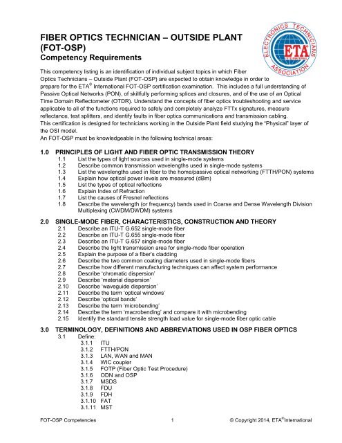
FIBER OPTICS TECHNICIAN – OUTSIDE PLANT(FOT-OSP)Competency RequirementsThis competency listing is an identification of individual subject topics in which FiberOptics Technicians – Outside Plant (FOT-OSP) are expected to obtain knowledge in order toprepare for the <strong>ETA</strong> ® <strong>International</strong> FOT-OSP certification examination. This includes a full understanding ofPassive Optical Networks (PON), of skillfully performing splices and closures, and of the use of an OpticalTime Domain Reflectometer (OTDR). Understand the concepts of <strong>fiber</strong> <strong>optics</strong> troubleshooting and serviceapplicable to all of the functions required to safely and completely analyze FTTx signatures, measurereflectance, test splitters, and identify faults in <strong>fiber</strong> <strong>optics</strong> communications and transmission cabling.This certification is designed for <strong>technician</strong>s working in the Outside Plant field studying the “Physical” layer ofthe OSI model.An FOT-OSP must be knowledgeable in the following technical areas:1.0 PRINCIPLES OF LIGHT AND FIBER OPTIC TRANSMISSION THEORY1.1 List the types of light sources used in single-mode systems1.2 Describe common transmission wavelengths used in single-mode systems1.3 List the wavelengths used in <strong>fiber</strong> to the home/passive optical networking (FTTH/PON) systems1.4 Explain how optical power levels are measured (dBm)1.5 List the types of optical reflections1.6 Explain Index of Refraction1.7 List the causes of Fresnel reflections1.8 Describe the wavelength (or frequency) bands used in Coarse and Dense Wavelength DivisionMultiplexing (CWDM/DWDM) systems2.0 SINGLE-MODE FIBER, CHARACTERISTICS, CONSTRUCTION AND THEORY2.1 Describe an ITU-T G.652 single-mode <strong>fiber</strong>2.2 Describe an ITU-T G.655 single-mode <strong>fiber</strong>2.3 Describe an ITU-T G.657 single-mode <strong>fiber</strong>2.4 Describe the light transmission area for single-mode <strong>fiber</strong> operation2.5 Explain the purpose of a <strong>fiber</strong>’s cladding2.6 Describe the two common coating diameters used in single-mode <strong>fiber</strong>s2.7 Describe how different manufacturing techniques can affect system performance2.8 Describe ‘chromatic dispersion’2.9 Describe ‘material dispersion’2.10 Describe ‘waveguide dispersion’2.11 Describe the term ‘optical windows’2.12 Describe ‘optical bands’2.13 Describe the term ‘microbending’2.14 Describe the term ‘macrobending’ and compare it with microbending2.15 Identify the standard tensile strength load value for single-mode <strong>fiber</strong> optic cable3.0 TERMINOLOGY, DEFINITIONS AND ABBREVIATIONS USED IN OSP FIBER OPTICS3.1 Define:3.1.1 ITU3.1.2 FTTH/PON3.1.3 LAN, WAN and MAN3.1.4 WIC coupler3.1.5 FOTP (Fiber Optic Test Procedure)3.1.6 ODN and OSP3.1.7 MSDS3.1.8 FDU3.1.9 FDH3.1.10 FAT3.1.11 MSTFOT-OSP Competencies 1 © Copyright 2014, <strong>ETA</strong> ® <strong>International</strong>
Fiber Optics Technician – Outside Plant Knowledge Competencies4.0 SINGLE-MODE FIBERS IN WAN, MAN, FTTx AND PREMISES NETWORKS4.1 List the types of single-mode <strong>fiber</strong> used in premises applications4.2 Describe acceptable methods of terminating single-mode <strong>fiber</strong>4.3 List the types of <strong>fiber</strong> used in metropolitan area networks (MANs)4.4 Describe the type of <strong>fiber</strong> used for Wavelength Division Multiplexing4.4.1 Dense Wavelength Division Multiplexing (DWDM)4.4.2 Coarse Wavelength Division Multiplexing (CWDM)4.5 List the <strong>International</strong> Telecommunication Union (ITU) specification for the two common singlemode<strong>fiber</strong> types4.6 Compare different techniques used in <strong>fiber</strong> manufacturing4.7 List different types of <strong>fiber</strong> optic cable tolerances4.8 List the <strong>fiber</strong> type specified in the ITU standard for FTTH4.9 Describe the different types of dispersion in single-mode applications5.0 FIBER OPTIC CABLES5.1 In a cross-section drawing of a stranded <strong>fiber</strong> optic cable, explain the purposes of each segment5.2 Identify the segments in the drawing of a cross section of a central tube <strong>fiber</strong> optic cable5.3 Explain why and where loose tube cable is used5.4 Compare tight-buffered cable with other types of <strong>fiber</strong> cable5.5 Explain the differences between the strength member in both stranded and central tube <strong>fiber</strong> opticcables5.6 Name the cable jacket material used in common types of <strong>outside</strong> <strong>plant</strong> cables5.7 Explain the purpose of installation specifications5.8 Define an indoor distribution cable structure and compare it with loose tube and central tube <strong>fiber</strong>optic cables5.9 List reasons for utilizing armored <strong>fiber</strong> cables5.10 Describe the purpose of cable ribbons and how they are used in <strong>fiber</strong> optic cables5.11 Explain the purpose and indicate where the TIA/EIA-598 color code is used5.12 Describe manufacturer markings on cable jackets and how they are used5.13 Explain the use of sequential cable markings5.14 Describe the two types of outdoor style cable structures5.15 Compare indoor and outdoor cables, their applications and benefits5.16 Describe the use of cable gels, powders and tapes5.17 Define tensile strength of a <strong>fiber</strong> cable5.18 Describe the dynamic load of a <strong>fiber</strong> cable5.19 Define ‘static load’ as it refers to <strong>fiber</strong> cabling5.20 Describe the detrimental effects of exceeding the minimum dynamic bend radius of a <strong>fiber</strong> cable5.21 Compare static versus dynamic bend radius in <strong>fiber</strong> optic cabling5.22 Describe the differences between <strong>fiber</strong> optic trunk, distribution and drop cables used in FTTxinstallations5.23 Explain the importance of the attenuation specification in <strong>fiber</strong> optic cables and how it is used5.24 Define microducts and microduct cables6.0 ACTIVE DEVICES6.1 Name the types of active optical devices used in <strong>fiber</strong> <strong>optics</strong>6.2 Explain the purposes and differences in the safety classifications for light sources used in <strong>fiber</strong>communications6.3 Name the type of light source used in OSP (Outside Plant) applications6.4 List the common wavelengths used in single-mode <strong>fiber</strong> communications systems and theadvantages and disadvantages of each6.5 Explain how to measure the output power of a light source6.6 Explain dBm and its role in testing transmit and receive optical power levels6.7 Explain the impact of Fresnel reflections on laser transmission6.8 Explain the impact of proper optical <strong>fiber</strong> cleaning materials and their effect on transmission quality6.9 Describe the basic role of the photodiode in <strong>fiber</strong> optic communications6.10 Describe the function and relationship of optical attenuators to detectorsFOT-OSP Competencies 2 © Copyright 2014, <strong>ETA</strong> ® <strong>International</strong>
Fiber Optics Technician – Outside Plant Knowledge Competencies7.0 CONNECTORS7.1 Identify standard <strong>fiber</strong> optic cable connector types7.2 Explain intrinsic factors applicable to losses in <strong>fiber</strong> connectors7.3 Explain extrinsic factors that cause attenuation in a <strong>fiber</strong> optic connection7.4 Describe how interconnection losses can be identified using common measuring equipment7.5 Explain how reflections can be identified in a completed cable link7.6 Describe a PC polish7.7 Describe a UPC polish7.8 Describe an APC polish7.9 Describe how and where pigtails are used in <strong>fiber</strong> optic cabling systems7.10 List steps taken to properly perform a visual inspection of an optical plug (connector)7.11 Describe proper cleaning of a single-mode plug and sleeve7.12 Describe contaminated or damaged connector ferrules7.13 Name common contaminants found in <strong>fiber</strong> cabling systems7.14 Describe common types and causes of <strong>fiber</strong> damage at the ferrule7.15 Describe a small form factor (SFF) connector as used in <strong>fiber</strong> optic transmission systems7.16 Describe the type of bonding techniques optimized for FTTx single <strong>fiber</strong> terminations7.17 Describe what an array connector is and its common applications8.0 PASSIVE COMPONENTS8.1 Explain the uses and benefits as well as disadvantages of using <strong>fiber</strong> optic signal splitters8.2 Describe where optical splitters are used in FTTx applications8.3 Explain wavelength division multiplexing (WDM)8.4 Explain how WDM is used in FTTH/PON systems8.5 Explain the differences between WDM and DWDM8.6 Explain the differences between WDM and CWDM8.7 Describe a wavelength independent (WIC) coupler and its characteristics8.8 Describe how an insertion loss test is conducted for optical splitters8.9 List the theoretical attenuation values for 1x2, 1x4, 1x16 and 1x32 splitters8.10 Explain how to test and compare measured versus theoretical losses of splitters8.11 Explain why an optical attenuator may be required in a <strong>fiber</strong> <strong>optics</strong> system9.0 TYPES OF SPLICING9.1 Explain the differences between intrinsic factors and extrinsic factors when splicing optical <strong>fiber</strong>s9.2 List extrinsic factors important in <strong>fiber</strong> splicing9.3 Describe correct <strong>fiber</strong> cable preparation9.4 Explain the purpose of index matching gel and where it is used9.5 Explain the benefit of index matching fluids9.6 Describe Telcordia GR-20 performance specification standards for mechanical and fusion splices9.7 Explain the purposes of the splice closure9.8 Describe the correct cleaving operation for a <strong>fiber</strong> optic splice9.9 Explain the purpose and the correct method of applying a splice protector9.10 Describe splice trays and their usage9.10.1 Identify the proper color code sequence for splice tray management9.11 Explain the role and benefits of pigtail splices in a single-mode system9.12 List the two coatings used in single-mode pigtail splicing9.13 Explain where mechanical splices are used in single-mode systems10.0 CABLE INSTALLATION10.1 Define ‘dynamic tensile loading’ of a <strong>fiber</strong> optic cable10.2 Explain ‘static tensile loading’ and compare with dynamic tensile loading10.3 Compare the dynamic bend radius minimums for common OSP <strong>fiber</strong> cables10.4 Describe the effects of exceeding minimum bend radius limitations10.5 Explain when and where bonding to ground is required10.6 Describe a pulling grip and explain its usage10.7 Describe where conduit should be installed to protect <strong>fiber</strong> optic cables10.8 Describe the National Electrical Code (NEC ® ) Article 770 rules pertaining to cabling10.9 Describe the role of the National Electric Safety Code (NESC) for aerial and buried installationsFOT-OSP Competencies 3 © Copyright 2014, <strong>ETA</strong> ® <strong>International</strong>
Fiber Optics Technician – Outside Plant Knowledge Competencies10.10 Explain why a mid-entry into an OSP cable may be required10.11 Explain the tension ratings of drop and trunk cables10.12 List the minimum depth for burial of a <strong>fiber</strong> optic cable drop10.13 Name cable management products used for cable slack in aerial installations10.14 Name cable management products used for slack cable in hubs and vaults10.15 List the maximum tension level for a <strong>fiber</strong> optic drop cable11.0 HARDWARE11.1 Explain common practices for <strong>fiber</strong> optic splice closures11.2 Explain the role of the Fiber Distribution Unit (FDU)11.3 Explain the role of the Fiber Distribution Hub (FDH) in FTTx applications11.4 Explain the role of the Fiber Access Terminal (FAT) in FTTx applications11.5 Explain the role of the Multiport Service Terminal (MST) in FTTx applications11.6 Describe how the mid-entry splice cables are routed through a splice enclosure11.7 Describe the different types of cable management products that are used at the hub locations11.8 Compare the options for cable routing in a hub location11.9 Explain the NEC ® requirement for outdoor cable entry into a building11.10 List the different types of innerduct products commonly used in <strong>fiber</strong> optic cabling11.11 Describe how a loose tube cable is installed and spliced at an entrance cabinet11.12 Describe the products, applications and options used in the Optical Distribution Network (ODN) forFTTx installations11.13 Describe the five installation/termination options for the FTTx drop cables12.0 FIBER OPTIC LINK12.1 List the three basic parts of a <strong>fiber</strong> <strong>optics</strong> system12.2 Explain how to prepare a basic optical link power budget12.3 Explain the purpose of a basic “not to exceed” OSP loss budget12.4 Explain how to measure the receive power levels of a <strong>fiber</strong> <strong>optics</strong> receiver12.5 Describe how to use an optical attenuator and calculate the proper reduction of signal output lightintensity12.6 Describe the topologies used in MAN applications12.7 Describe the topology used in an FTTx installation13.0 OPTICAL FIBER MEASUREMENT AND TESTING13.1 List the types of attenuation in <strong>fiber</strong> <strong>optics</strong> cables13.2 Explain how to properly use an Optical Loss Test Set13.3 Explain when 2 KHz modulation of the <strong>fiber</strong> optic light source would be used13.4 Explain the proper use of the <strong>fiber</strong> optic power meter (OPM)13.5 Describe how to locate a fault using an Optical Time Domain Reflectometer (OTDR)13.6 Compare fusion and mechanical splice, connector, and splitter signatures when using the OTDR13.7 Describe a micro/macrobend at a splice closure13.8 Describe the ‘Fiber Identifier’ and its operation13.9 Explain how to measure Fresnel reflections at patch panels13.10 Explain why bi-directional tests are performed13.11 Explain the reasons for dual wavelength testing13.12 Explain when to test using a light source and power meter13.13 Explain what tests the OTDR is used for13.14 Describe the causes of ghost reflections13.15 Explain how the <strong>fiber</strong> optic talk set is used13.16 Describe when and where the visual laser is commonly used14.0 LINK AND CABLE TESTING14.1 Explain why an end-to-end optical loss test is performed14.2 Describe the transmitter power test using the optical power meter14.3 Describe the receiver optical power test using the optical power meter14.4 Explain the purpose of an acceptance test to verify <strong>fiber</strong> optic cable values using an OTDR14.5 Explain how an acceptance test for a mechanical splice is made14.6 Describe the OTDR’s ‘dead zone’FOT-OSP Competencies 4 © Copyright 2014, <strong>ETA</strong> ® <strong>International</strong>
Fiber Optics Technician – Outside Plant Knowledge Competencies14.7 Compare fusion and mechanical splice loss requirements per ANSI/TIA/EIA-758-A and TelcordiaGR-2014.8 Explain how to measure a fusion splice14.9 Explain how to find the actual fault location of a non-reflective break14.10 Explain how to perform a bi-directional test on a <strong>fiber</strong> span14.11 Describe documentation of the values of component losses14.12 Describe how to document the end-to-end attenuation value of a <strong>fiber</strong> span14.13 Describe what tests tier one and tier two testing involves15.0 SAFETY15.1 Describe laser classifications (per CDRH – Center for Devices & Radiological Health)15.2 Describe MSDS (Material Safety Data Sheets) regulations and the OSP products for which theywould be required15.3 Describe basic <strong>fiber</strong> optic safety practices in regard to eyes, skin and lungs, as well as safe <strong>fiber</strong>disposal methods15.4 Describe safe cabling operations when working in confined spacesEnd of FOT – OSP Knowledge Competencies(15 major categories)Find An <strong>ETA</strong> ® Approved Fiber OpticsSchool SiteFind An <strong>ETA</strong> ® Test Sitehttp://www.eta-i.org/<strong>ETA</strong>FOISchools.pdfhttp://www.eta-i.org/testing.htmlSuggested Study Materials and Resources for Fiber Optics Technician – Outside Plant Certification:Troubleshooting Optical Fiber Networks: Understanding and Using Optical Time-DomainReflectometers, 2E; Duwayne Anderson, Larry Johnson, Florian Bell; ISBN 978-0120586615;Elsevier Academic Press; May 2004; hardcover; 437 ppg; 800-545-2522Technology Series DVDs and CDs; The Light Brigade, 800-451-7128, www.lightbrigade.com. Availablethrough <strong>ETA</strong> 800-288-3824, www.eta-i.orgCabling: The Complete Guide to Copper and Fiber-Optic Networking, 5E; Andrew Oliviero, BillWoodward; ISBN 978-1-118-80732-3; Sybex, Inc; March 2014; paperback; 1284 ppg. —Availablethrough <strong>ETA</strong> at 800-288-3824, www.eta-i.orgTechnicians Guide to Fiber Optics, 4E; Donald J. Sterling; ISBN 1-4018-1270-8; Delmar Learning;Dec 2003; hardcover; 384 ppg; Available through <strong>ETA</strong> 800-288-3824, www.eta-i.orgFiber Optic Installer and Technician Guide; Bill Woodward, Emile Husson; ISBN 978-0782143904; Sybex,Inc; July 2005; hardcover; 496 ppg; Available through <strong>ETA</strong> 800-288-3824, www.eta-i.orgFiber to the Home: The New Empowerment; Paul E. Green, Jr; ISBN 978-0471742470; Wiley-Interscience;Oct.2005; hardcover; 144 ppgFTTX Concepts and Applications; Gerd Keiser; ISBN 978-0471704201; Wiley-IEEE Press; Jan.2006;hardcover; 312 ppgFTTx PON Technology and Testing; Andre Girard, PhD; EXFO Electro-Optical Engineering, Inc.;www.exfo.com; 2005; paperback, 200 ppg.Understanding Fiber Optics, 5E; Jeff Hecht; ISBN: 978-0131174290; Prentice-Hall; April 2005; hardcover;800 ppgNational Electrical Code, 2014; National Fire Protection Assn., Sept.,2013; www.nfpa.org<strong>ETA</strong> certification programs are accredited through the ICAC,complying with the ISO/IEC 17024 standard.FOT-OSP Competencies 5 © Copyright 2014, <strong>ETA</strong> ® <strong>International</strong>