Replica molding with a polysiloxane mold provides this ... - EPFL
Replica molding with a polysiloxane mold provides this ... - EPFL
Replica molding with a polysiloxane mold provides this ... - EPFL

Create successful ePaper yourself
Turn your PDF publications into a flip-book with our unique Google optimized e-Paper software.
REVIEWS<br />
4.1.2. Fabrication of Complex Optical Surfaces<br />
<strong>Replica</strong> <strong><strong>mold</strong>ing</strong> against a deformed PDMS <strong>mold</strong> <strong>provides</strong><br />
a new strategy for making topologically complex structures<br />
and optically functional surfaces. [35, 168] It allows the sizes and<br />
shapes of features present on the surface of the <strong>mold</strong> to be<br />
changed in a controlled way (by mechanical compression,<br />
bending, stretching, or a combination of these deformations)<br />
and generates complex structures from simple, regular<br />
structures on planar surfaces. The highly isotropic deformation<br />
of the PDMS <strong>mold</strong> even permits patterned microstructures<br />
to be formed <strong>with</strong> gradients in size and shape. The<br />
relief features on the PDMS <strong>mold</strong> are reconfigured by<br />
mechanical deformation, and the deformed structures are<br />
replicated by casting an UV-curable liquid PU or a thermally<br />
curable epoxy against it. The capability and feasibility of <strong>this</strong><br />
procedure has been demonstrated by the production of [35]<br />
1) diffraction gratings <strong>with</strong> periods smaller than the original<br />
grating used as the master to cast the PDMS <strong>mold</strong>, 2) chirped,<br />
blazed diffraction gratings on planar and curved surfaces,<br />
3) patterned microfeatures on the surfaces of approximately<br />
hemispherical objects, and 4) arrays of rhombic microlenses.<br />
Figure 21 summarizes the typical procedures used in replica<br />
<strong><strong>mold</strong>ing</strong> against elastomeric <strong>mold</strong>s under mechanical deformation.<br />
[35] Figure 21 A shows the procedure for replica <strong><strong>mold</strong>ing</strong><br />
against a PDMS <strong>mold</strong> under mechanical compression. If<br />
desired, <strong>this</strong> procedure can be repeated, using the PU replica<br />
as the starting point, to make structures more complex than<br />
G. M. Whitesides et al.<br />
can be generated in one cycle (although <strong>with</strong> some degradation<br />
in the quality of the fabricated structures). Using a test<br />
structure of parallel lines, two cycles of compression and<br />
replication reduced the size of some features (that is, the<br />
recessed areas on the <strong>mold</strong>) from 1.6 mm to about 200 nm, and<br />
reduced the period of <strong>this</strong> test pattern from 3.6 to about 1.5<br />
mm. [35] Figure 21 B illustrates the procedure that we used to<br />
fabricate diffraction gratings on cylindrical surfaces. A thin<br />
PDMS <strong>mold</strong> (ca. 50 mm thick) was bent to make conformal<br />
contact <strong>with</strong> a curved surface coated <strong>with</strong> a thin film of liquid<br />
PU. After curing the PU, the PDMS <strong>mold</strong> was removed to<br />
reveal the PU replica on the surface of the cylindrical<br />
substrate. Figure 21 C shows a similar procedure that was<br />
used to produce an approximately hemispherical object<br />
having micropatterned relief structures on its surface. A thin<br />
PDMS <strong>mold</strong> (ca. 1 mm thick) was mounted across the end of a<br />
hollow glass tube and deformed by applying positive or<br />
negative pressure through the tube. The resulting curved<br />
surface was then replicated in PU.<br />
By compressing one end of the elastomeric <strong>mold</strong> more than<br />
the other, it was straightforward to fabricate a chirped<br />
diffraction grating, a grating whose period changes continuously<br />
<strong>with</strong> position. [172] More interestingly, the shape of the<br />
diffracting elements was largely preserved in <strong>this</strong> process: If<br />
we used a blazed grating as the starting master, the resulting<br />
chirped PU replica was also a blazed grating (Figure 22). [35]<br />
The period (L) of <strong>this</strong> chirped, blazed grating changed<br />
continuously from a value of about 1.55 to about 1.41 mm over<br />
a distance of approximetly 0.9 cm; the rate of chirping dL/dz<br />
was approximately 1.6 10 5 . This grating was characterized<br />
in transmission at normal incidence. Figure 22 C shows the<br />
diffraction patterns (the zero-order and the two first-order<br />
peaks) of the PDMS <strong>mold</strong>, its PU replica, and the chirped PU<br />
grating. The first diffraction peak shifted continuously in<br />
position as the laser spot was scanned across the chirped<br />
grating along the z direction.<br />
Figure 23 shows the SEM image of a hemispherical PU<br />
object <strong>with</strong> a pattern of corner cubes on its surface. [35, 168] The<br />
shape of <strong>this</strong> polymeric object can be easily tuned by changing<br />
the thickness of the PDMS <strong>mold</strong> or the applied pressure or<br />
both. We have made a range of different patterns and relief<br />
structures; the smallest feature had a size of about 1.5 mm.<br />
4.2. Microtransfer Molding<br />
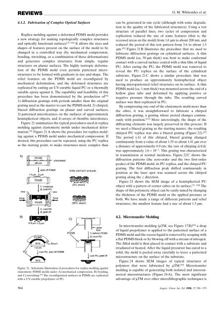
Figure 21. Schematic illustration of procedures for replica <strong><strong>mold</strong>ing</strong> against<br />
elastomeric PDMS <strong>mold</strong>s under A) mechanical compression, B) bending,<br />
and C) stretching. [35] The reconfigurated surfaces in PDMS are replicated<br />
<strong>with</strong> a UV-curable prepolymer of PU.<br />
In microtransfer <strong><strong>mold</strong>ing</strong> (mTM, see Figure 17 B) [36] a drop<br />
of liquid prepolymer is applied to the patterned surface of a<br />
PDMS <strong>mold</strong> and the excess liquid is removed by scraping <strong>with</strong><br />
a flat PDMS block or by blowing off <strong>with</strong> a stream of nitrogen.<br />
The filled <strong>mold</strong> is then placed in contact <strong>with</strong> a substrate and<br />
irradiated or heated. After the liquid precursor has cured to a<br />
solid, the <strong>mold</strong> is peeled away carefully to leave a patterned<br />
microstructure on the surface of the substrate.<br />
Figure 24 shows SEM images of typical structures of<br />
polymers that were fabricated by mTM. [36] Microtransfer<br />
<strong><strong>mold</strong>ing</strong> is capable of generating both isolated and interconnected<br />
microstructures (Figure 24 A). The most significant<br />
advantage of mTM over other microlithographic techniques is<br />
564 Angew. Chem. Int. Ed. 1998, 37, 550 ± 575