Replica molding with a polysiloxane mold provides this ... - EPFL
Replica molding with a polysiloxane mold provides this ... - EPFL
Replica molding with a polysiloxane mold provides this ... - EPFL

You also want an ePaper? Increase the reach of your titles
YUMPU automatically turns print PDFs into web optimized ePapers that Google loves.
Soft Lithography<br />
Figure 26. Dependence of the rate of capillary filling, represented<br />
by z(dz/dt) in 10 4 mm 2 s 1 , and the imbibition shape (insets) on interfacial<br />
free energies of the surfaces [189] as described <strong>with</strong> the the dynamic contact<br />
angle q a between the liquid polymer and the SAM-derivatized surface.<br />
liquids <strong>with</strong> high advancing contact angles (Figure 26 e, f) the<br />
bulk liquids flow as a whole <strong>with</strong>out having precursor<br />
structures. The imbibition shapes can be described as wedge<br />
or bulk-flow.<br />
4.3.2. MIMIC of Solventless Systems<br />
The capability and feasibility of MIMIC have been<br />
demonstrated by the fabrication of patterned structures from<br />
a variety of liquid prepolymers: PU, polyacrylates, and<br />
[37, 179]<br />
epoxies. These prepolymers have a shrinkage of less<br />
than 3 % after curing. [171] The cured polymers, therefore,<br />
possess almost the exact dimensions and shapes of the<br />
channels in the surface of the PDMS <strong>mold</strong>; they can be<br />
directly used as masks in the etching of the underlying<br />
substrates. Figure 27 shows SEM images of polymeric microstructures<br />
that were fabricated by MIMIC. The polymer<br />
REVIEWS<br />
thicknesses) in a single step (Figure 27 C). [179] Such complex<br />
arrays of micro and submicrometer scale channels filled<br />
completely; in some regions of these structures, features are<br />
connected to one another by channels <strong>with</strong> thicknesses of less<br />
than 100 nm. The support used in MIMIC could have relief<br />
patterns on its own surface. Figure 27 D shows the SEM image<br />
of a free-standing microstructure of PU that was formed<br />
[37, 179]<br />
between two PDMS <strong>mold</strong>s. Each PDMS <strong>mold</strong> has a<br />
relief pattern of parallel lines on its own surface. After the<br />
filling <strong>with</strong> liquid prepolymer and the curing of the prepolymer<br />
into a solid, the two PDMS <strong>mold</strong>s were separated. The<br />
cross-linked polymeric microstructure remained on the surface<br />
of one of the two PDMS <strong>mold</strong>s and could be easily<br />
released. These two layers of polymeric lines formed one<br />
interconnected polymeric microstructure. This type of freestanding<br />
microstructure, two layers <strong>with</strong> an independent relief<br />
structure in each, cannot be fabricated by photolithography. [10]<br />
4.3.3. MIMIC of Systems <strong>with</strong> Solvents<br />
Although MIMIC was developed based on prepolymers<br />
having no solvents, it has also been extended to those systems<br />
where solvents are involved. [182±186] The solvents were evaporated<br />
after the solutions had filled the channels. The only<br />
requirement seems to be that the solvent does not swell<br />
PDMS. It has been extremely difficult (or impossible) to<br />
fabricate patterned structures of those materials such as<br />
polymer beads (Figure 28 A, B) and ceramics (Figure 28 E, F)<br />
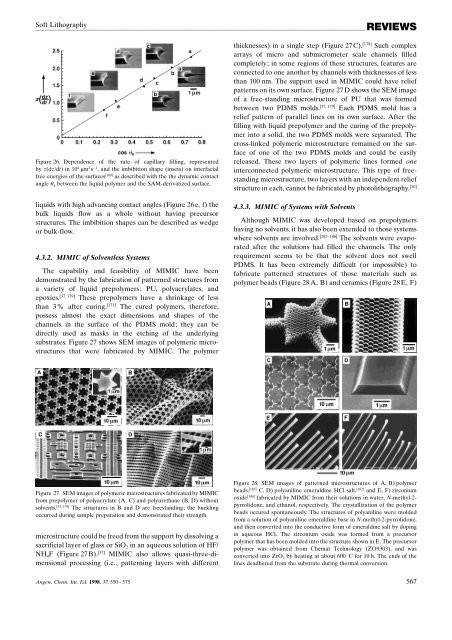
Figure 27. SEM images of polymeric microstructures fabricated by MIMIC<br />
from prepolymer of polyacrylate (A, C) and polyurethane (B, D) <strong>with</strong>out<br />
solvents. [37, 179] The structures in B and D are freestanding; the buckling<br />
occurred during sample preparation and demonstrated their strength.<br />
microstructure could be freed from the support by dissolving a<br />
sacrificial layer of glass or SiO 2 in an aqueous solution of HF/<br />
NH 4 F (Figure 27 B). [37] MIMIC also allows quasi-three-dimensional<br />
processing (i.e., patterning layers <strong>with</strong> different<br />
Figure 28. SEM images of patterned microstructures of A, B) polymer<br />
beads, [183] C, D) polyaniline emeraldine HCl salt, [182] and E, F) zirconium<br />
oxide [180] fabricated by MIMIC from their solutions in water, N-methyl-2-<br />
pyrrolidone, and ethanol, respectively. The crystallization of the polymer<br />
beads occured spontaneously. The structures of polyaniline were <strong>mold</strong>ed<br />
from a solution of polyaniline emeraldine base in N-methyl-2-pyrrolidone,<br />
and then converted into the conductive form of emeraldine salt by doping<br />
in aqueous HCl. The zirconium oxide was formed from a precursor<br />
polymer that has been <strong>mold</strong>ed into the structure shown in E. The precursor<br />
polymer was obtained from Chemat Technology (ZO9303), and was<br />
converted into ZrO 2 by heating at about 600 8C for 10 h. The ends of the<br />
lines deadhered from the substrate during thermal conversion.<br />
Angew. Chem. Int. Ed. 1998, 37, 550 ± 575 567